Solar reactors for thermochemical CO 2 and H 2 O splitting via metal oxide redox reactions
|
|
|
- Roger Carroll
- 5 years ago
- Views:
Transcription

1 Solar reactors for thermochemical CO 2 and H 2 O splitting via metal oxide redox reactions P. Furler a, J.R. Scheffe a, D. Marxer a, A. Steinfeld a,b a Dempartment of Mechanical and Process Engineering, ETH Zurich, Switzerland b Solar Technology Laboratory, Paul Scherrer Institute, Switzerland SFERA II SUMMER SCHOOL 2014, Odeillo, France
2 Outline Introduction Thermochemical fuel production 2-step thermochemical cycles Metal oxide redox pairs Solar reactor concepts (DLR, SNL, ETH) Syngas production by simultaneous splitting of H 2 O and CO 2 Reactive metal oxide structure Summary and conclusions

 Image: http://www.brightsourceenergy.")
3 Solar thermochemical fuel production Solar concentration H 2 O/CO 2 H 2 O/CO 2 dissociation CO 2 capture Q solar H 2 O H O 2 O 2 Absorber CO 2 CO O 2 H 2 /CO Heliostat array Catalytic fuel synthesis nco + 2n H 2 C n H 2n + nh 2 O Liquid fuels (Diesel, Jet fuel, Ethanol ) Image:

4 H 2 O / CO 2 dissociation pathways Direct solar thermolysis Solar thermochemical redox cycles H 2 O CO 2 T >> 2500 C H 2 O H O 2 CO 2 CO O 2 1 st step : solar reduction MO OX MO red + O 2 2 nd step: oxidation T ~1500 C T ~900 C O 2 H 2 O MO red + H 2 O MO OX + H 2 H 2 CO 2 MO red + CO 2 MO OX + CO CO H 2 / CO / O 2 Very high temperatures High temperature gas separation or rapid quenching No separation needed: H 2 /CO generated separately from O 2 Operating temperature much less than direct gas splitting
5 Solar H 2 O / CO 2 splitting 2-Step thermochemical cycles MO ox MO red = metal oxide = metal or lower-valence metal oxide MO ox 1 st step : solar reduction MO ox MO red O 2 MO red O 2 H 2 O/CO 2 CO 2 capture recycle 2 nd step: oxidation MO red + H 2 O MO ox + H 2 MO red + CO 2 MO ox + CO CeO 2 H 2 / CO liquid fuels (diesel, jet fuel ) Solar Energy, 2005, 78,
6 Common metal oxide redox pairs Volatile metal oxides Undergo gas-solid phase transition: Zinc oxide: ZnO(s) Zn(g) Tin oxide: SnO 2 (g) SnO(g) Greater oxygen exchange capability than non-volatile MO: More O 2 release / uptake => more fuel per mass of oxide Fast reaction kinetics Volatile products must be separated or rapidly quenched: not solved today in an energ. efficient fashion today J. R. Scheffe and A. Steinfeld. Oxygen exchange materials for solar thermochemical splitting of H 2 O and CO 2 : a review. Materials Today 2014, 0. Non-volatile metal oxides Remain in the solid state during reduction Non-volatile (stoichiometric): Iron oxide: Fe 3 O 4 FeO Ferrite: M x Fe 3-x O 4 xmo+(3-x)feo Hercynite Gen. form solid solutions upon reduction: i.e. Fe 3 O 4 (s) FeO-Fe 3 O 4 (s) Non-volatile (non-stoichiometric): Remain crystall. stable while lattice accommodates changes in anion or cation vacancies concentrations Ceria: CeO 2 CeO 2-δ Perovskite: ABO 3 ABO 3-δ 02/07/2014 6
7 Solar H 2 O / CO 2 splitting 2-Step CeO 2 cycle CeO 2 1 st step : solar reduction CeO 2 CeO 2 δ + δ 2 O 2 CeO 2 δ O 2 H 2 O/CO 2 recycle 2 nd step: oxidation CeO 2 δ + δh 2 O CeO 2 + δh 2 CeO 2 δ + δco 2 CeO 2 + δco CeO 2 H 2 / CO liquid fuels (diesel, jet fuel ) CO 2 capture Journal of Physics and Chemistry of Solids, 1975, 36,


8 Solar reactor technology DLR, Germany ZnFe 2 O 4 U. of CO, USA NiFe 2 O 4 Niigata U., Japan NiFe 2 O 4 H 2 N 2 + O 2 H 2 O N 2 Solar Energy, 2011, 85, Solar Energy, 2013, 90, JSEE, 2008, 130, SNL, USA CoFe 2 O 4, CeO 2 CNRS-PROMES, F CeO 2 ETH / PSI, CH CeO 2 JSEE, 2008, 130, Solar Energy, 2006, 80, Science 2010, 330 (6012),
 Insulation Steel housing Reactive coating (Zn x Fe 3-x O 4 ) 1 st step : solar reduction")

9 Inlet DLR Hydrosol reactor (ferrite) Quartz window T = C C O 2 O 2 H 2 H 2 H 2 Concentrated solar radiation O 2 Honey comb structure (SiC) Insulation Steel housing Reactive coating (Zn x Fe 3-x O 4 ) 1 st step : solar reduction Zn x Fe 3 x O 4 Zn x Fe 3 x O 4 δ + δ 2 O 2 O 2 H 2 O 2 nd step: oxidation Zn x Fe 3 x O 4 δ + δh 2 O Zn x Fe 3 x O 4 + δh 2 H 2 Materials, 2013, 6, JSSE, 2006, 128, Int.J.Hydrogen Energy, 2009, 34,


10 DLR Hydrosol reactor Experimental results Experimental conditions: Reduction Oxidation Power input: > 45 kw < 45 kw Gas flows: N 2 : 15Nm 3 h -1 N 2 : 15 Nm 3 h -1 H 2 O: 3.5 kg h -1 Accurate temperature control by adjusting P solar Dual-cavity concept worked Successfully produced H 2 But decreasing rates and yield over time indicate instable material Solar Energy, 2011, 85,
11 DLR Hydrosol reactor Simple and scalable concept No moving / rotating parts No gas phase reactions Quasi continuous product stream because of dual-cavity approach Good control of gas flows across honey comb structure Solar engineering concept workes Accurate temperature control by P solar Volumetric absorption of concentrated radiation because of honey comb structure Low mass loading of active material < 10% because ferrites are coated on inert honey combs Inert material has to be heated in every cycle => limits efficiency The more active material the more fuel can be produced per cycle Side reactions with supporting structure Active ferrite coating is deactivated over time Sensible heat recuperation from solid not implemented


12 Sandia NL CR5 reactor T = 1550 C CeO 2 1 st step : solar reduction O 2 CeO 2 CeO 2 δ + δ 2 O 2 CeO 2 δ T = 1100 C H 2 O/CO 2 2 nd step: oxidation CeO 2 δ + δh 2 O CeO 2 + δh 2 CeO 2 δ + δco 2 CeO 2 + δco H 2 CO JSEE, 2008, 130, recycle

 Heat recuperation is important for achieving high")

13 Sandia NL CR5 reactor Heat recuperation concept Each Ring rotates in opposite direction to its neighbors Recuperation of sensible heat by thermal radiation At high T radiation is dominating mode of heat transfer (ε σ T 4 ) Heat recuperation is important for achieving high efficiencies R. Hogan et al.. ASME Proceedings of the 6 th International Conference on Energy Sustainability, San Diego, USA,


 as expected Sandia Report SAND2012-5658,")
14 CR5 reactor Experimental results Experimental conditions: Reduction Oxidation Power input: 2-9 kw Gas flows: Ar: 20 L min -1 CO 2 : 20 L min -1 Reactor was successfully operated on sun for several hours Good temperature control Problems with mechanical stability of rotating rings Stoichiometric fuel production (CO:O 2 = 2) as expected Sandia Report SAND ,

15 CR5 reactor Sensible heat recuperation inherently included Important aspect for achieving high efficiencies Continuous process Reduction and oxidation proceed simultaneously Hot and cold zones are maintained at constant temperatures Reduces energy requirements for heating of reactor components Accurate temperature control by adjustment of the RPM Low mass loading of active material Only fraction of the rings consists of active redox material Inert material of the rings need to be heated in every cycle => limits efficiency High optical thickness of CeO 2 structure Limits heat transfer => limits fuel production and efficiency Rotating high temperature ceramic parts Mechanical failure of rotating rings was observed and caused major problems Complex gas flow control Cross-flow of O 2 from the reduction zone to the oxidation zone Fraction of CeO 2-δ is oxidized with O 2 High gas flows needed => low product gas concentration


 Science 2010, 330")
, 6098-6103 Energy Fuels 2012,")
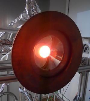
16 ETH Solar Reactor Porous CeO 2 Al2O3-SiO2 insulation Reactor Thermal Oxidation Reduction: ΔH CeO 2 CeO2 δ + δ 2 δ + δh 2 O H CeO 2 O δh 2 Reactor Front (water-cooled) CeO 2 δ + δco 2 H CeO2 + δco X μm Quartz Window X 1000 Syngas (H 2 / CO) 100 μm O 2 CO C O H 2 2 H2 O 2 Concentrated Solar Radiation 10 mm Inconel Shell Purge H 2 O / Gas CO 2 (Ar) Science 2010, 330 (6012), Energy Environ. Sci. 2012, 5 (3), Energy Fuels 2012, 26 (11),
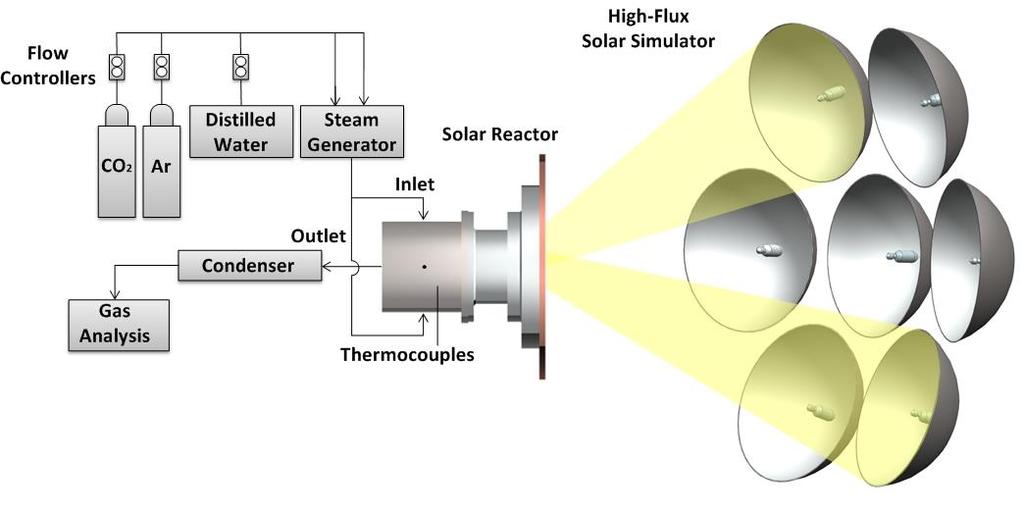


17 Experimental setup Energy Environ. Sci. 2012, 5 (3),
18 Syngas production by simultaneous splitting of CO 2 and H 2 O
19 Experimental results Simultaneous H 2 O / CO 2 splitting (H 2 O:CO 2 = 5.7) Experimental conditions: Reduction Oxidation Power input: 3.6 kw 0.8 kw Gas flows: Ar: 2 l min -1 Ar: 2 l min -1 Ceria structure: Ceria Felt Total Mass: 127 g CO 2 : l min -1 H 2 O: 2.15 l min -1 Stoichiometric fuel production as expected (O 2 :fuel = 1:2) (H 2 O H O 2 ) (CO 2 CO O 2 ) No gas phase hydrocarbons detected No C depositions No impurities detected which could damage catalyst of FT unit Energy Environ. Sci. 2012, 5 (3),
20 Experimental results Syngas composition (H 2 :CO) vs. co-feeding ratio (H 2 O:CO 2 ) Experimental conditions: Reduction Oxidation Power input: 3.6 kw 0.8 kw Gas flows: Ar: 2 l min -1 Ar: 2 l min -1 CO 2 : l min -1 H 2 O: l min -1 Ceria structure: Ceria felt Total mass: 127 g Syngas composition (H 2 :CO) adjustable in a wide range ( ) by controlling the co-feeding ration (H 2 O:CO 2 ) Syngas composition increases linearly with increasing H 2 O:CO 2 ratios e.g. co-feeding with H 2 O:CO 2 = 6.5 yields syngas with H 2 :CO = 2 Syngas suitable for FT synthesis Energy Environ. Sci. 2012, 5 (3),
21 Experimental results Consecutive H 2 O / CO 2 splitting (H 2 O:CO 2 = 6.7) Experimental conditions: Reduction Oxidation Power input: 3.6 kw 0.7 kw Gas flows: Ar: 2 l min -1 Ar: 2 l min -1 Ceria structure: Ceria Felt Total Mass: 127 g CO 2 : 0.33 l min -1 H 2 O: 2.20 l min -1 Energy Environ. Sci. 2012, 5 (3), Philipp Furler
22 Solar-to-fuel energy conversion efficiency η solar to fuel = ΔH fuel r fuel dt P solar dt + E inert r inert dt Direct impact on fuel production cost Reactive Structure Heat and mass transfer properties η solar-to-fuel % Reactive Material Doped CeO 2 Other metal oxides Perovskites Reactor technology Geometry and scale-up Operating conditions Heat recovery 22
23 Reactive CeO 2 structures
, 1797-1801 Energy Environ. Sci. 2012, 5 (3), 6098-6103 Energy Fuels 2012, 26 (11), 7051-7059")
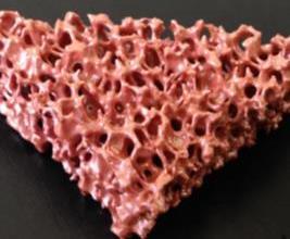
24 Structural improvements of Ceria x μm High SSA rapid oxidation kinetics but low specific mass HT limited during reduction step Limitations: HT limited during reduction pores in mm-range vol. absorption fast heating rates high specific mass high mass loading Science 2010, 330 (6012), Energy Environ. Sci. 2012, 5 (3), Energy Fuels 2012, 26 (11),
 Macro-porous structure")

 CeO 2")
, 7051-7059 Al 2 O 3 -SiO 2 insulation")
25 CeO 2 Structure CeO 2 RPC (Reticulated Porous Ceramic) Macro-porous structure enables penetration and absorption of concentrated solar radiation Faster heating rates Temperature gradients minimized High mass loading within reactor (~1500 g) CeO 2 laminate CeO 2 RPC Energy Fuels 2012, 26 (11), Al 2 O 3 -SiO 2 insulation Inconel shell
 CeO 2 RPC Ceria Structure: Ceria")


26 Comparison felt vs. RPC Experimental Conditions Reduction Oxidation Power Input: 3.6 kw 0.7 kw CeO 2 felt Gas Flow: 2 l min -1 Ar 3 l min -1 CO 2(g) CeO 2 RPC Ceria Structure: Ceria RPC: 1416 g, Ceria felt; 90 g Rate (ml min -1-1 g -1-1 CeO Rate (ml min -1 2 ) ) 0, , , , ,00 0 O 2 evolution CO CO evolution O 22 evolution CeO 22 felt O 22 evolution CeO 22 RPC Heating Rate CeO2 felt felt Heating Rate CeO2 RPC O2 x O evolution 100 CeO2 μm felt felt O2 O2 evolution CeO2 RPC 2,5 x μm Rate Rate (ml min (ml -1-1 min g -1-1 CeO -1 ) 2 ) 400 2, , ,0 O : -1 : -1 2 Felt : 0.24 l CO CO Felt : 0.49 l O 2 2 : -1 : -1 2 Felt RPC : 2.66 : 4.00 ml l g -1 Felt : 5.39 ml g ,5 CO RPC : 8.27 l CO O 2 RPC : 2.83 ml g -1 RPC : 5.86 ml g -1 0, ,0 Time (min) Time (min) CO evolution CeO 22 felt CO evolution CeO 22 RPC x μm x μm Overall 17 times higher fuel production per cycle with RPC structure Energy Fuels 2012, 26 (11),
27 Experimental results Conditions Reduction Oxidation Power Input: kw 0 kw Gas Flow: 2 l min -1 Ar 2 l min -1 CO 2 Mass loading: 1416 g 0,6 reduction oxidation 2000 Rate (ml min -1 g -1 CeO 2 ) 0,5 0,4 0,3 0,2 0,1 T ceria O 2 : 2.76 ml g ml g ml g -1 CO: 5.69 ml g ml g ml g kw 3.4 kw 2.8 kw Temperature ( C) 0, Time (min) Energy Fuels 2012, 26 (11),
28 Experimental results Solar-to-fuel conversion efficiency solar-to-fuel (%) η RPC = 1.7 % t Reduction T Ceria P solar (kw) solar-to-fuel => 12x η Felt (0.15 %) => 4 x η bricks (0.4%) η average = Reduction step duration (min) ΔH fuel r fuel dt P solar dt + E inert r inert dt Nominal reactor temperature ( C) Improved heat-transfer Improved specific mass Energy Fuels 2012, 26 (11),


, 6098-6103 Energy Fuels 2012, 26 (11),")
29 Structural improvements of Ceria x μm High SSA rapid oxidation kinetics but low specific mass HT limited during reduction step Limitations: 1) HT limited during reduction pores in mm-range vol. absorption fast heating 2) SSA limited during oxidation pores in the µm-range increase SSA fast oxidation Science 2010, 330 (6012), Energy Environ. Sci. 2012, 5 (3), Energy Fuels 2012, 26 (11), Phys. Chem. Chem. Phys. 2014,


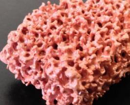

30 SEM micrographs single-scale RPC vs. multi-scale RPC 250 µm 250 µm Phys. Chem. Chem. Phys. 2014,
31 Experimental results Solar reactor experiment Conditions Reduction Oxidation Power Input: 3.8 kw 0 kw Gas Flow: Mass loading: 2 l min -1 Ar (single) 6 l min -1 Ar (dual) single: 1416 g, dual: 998 g 2 l min -1 CO 2 (single) 6 l min -1 CO 2 (dual) 1,4 reduction oxidation 2000 Rate (ml min -1 g -1 CeO 2 ) 1,2 1,0 0,8 0,6 0,4 0,2 T Ceria O 2,single : 2.3 ml g -1 O 2,dual : 2.52 ml g -1 single-scale RPC dual-scale RPC CO single : 4.7 ml g -1 CO dual : 5.02 ml g Temperature (K) Energy Fuels 2012, 26 (11), Phys. Chem. Chem. Phys. 2014, , Time (min)
32 1 g -1 CeO2 ) C) %) C) Peak rate (ml min -1 g -1 CeO2 ) Temperature ( C) Experimental results 290 redox cycles Conditions Reduction Oxidation Power Input: 3.8 kw..0 kw Gas Flow: 6 l min -1 Ar 6 l min -1 CO 2.. L min -1 H 2 O Mass loading: 998 g (a) 1.4 (I) (II) (III) (IV) CO rate H 2 rate Temperature Cycle number (-) (b) (c) kW 3.8kW 2.8kW H Submitted to Energy Environ. Sci. June T
33 ETH reactor Simple and scalable concept No moving / rotating parts No gas phase reactions Cavity receiver ensures high solar absorption efficiency 90% of incoming solar radiation is absorbed Ceria RPC structure offers advantageous properties Volumetric absorption of concentrated radiation because mm-sized pores -> high heating rates during solar reduction SSA because of µm-sized pores -> fast oxidation reaction kinetics High mass loading of active material and no side reactions Stable syngas production over time (no side reactions) Not a continuous process Sensible heat recuperation from solid not implemented
34 Summary and conclusions Important aspects of solar reactors Simple and scalable design No moving / rotating high temperature ceramic parts Efficient absorption of concentrated radiation Cavity receiver-type concepts Fast and uniform heating of metal oxide Requires metal oxide structure which can volumetrically absorb radiation Foam type or honey comb structures Particles High mass loading of redox active material High fuel production and η solar-to-fuel Stable metal oxide material Side reactions or strong sintering and loss of activity are not permitted Potential for reaching high η solar-to-fuel Heat recuperation from the solids and gases should be possible
35 Summary and conclusions Experiments ETH reactor Syngas production by simultaneous splitting of H 2 O and CO 2 Syngas composition can be controlled by the H 2 O/CO 2 co-feeding radio Syngas is suitable for FT-synthesis (composition, purity) Heat transfer limitation during thermal reduction: RPC structure with pores in the mm-range Volumetric absorption => fast / homogenous heating Higher specific mass => higher ceria mass loading Surface limitation during oxidation: Dual-scale RPC with pores in the mm-range and µm-range Increased SSA => fast oxidation kinetics RPC structure allowed to enhance: the fuel production per unit time η solar-to-fuel = 1.7 %


36 Acknowledgments PREC ETH & STL PSI EMPA: Dr. Ulrich Vogt, Michal Gorbar, Alexander Bonk EU-SOLAR-JET European Commission Contract No CCEM EU-ERC Advanced Grant SUNFUELS No
37 Thank you! Institute of Energy Technology Philipp Furler Dr. sc. ETH ETH Zurich Sonneggstrasse Zurich Switzerland phone: furlerp@ethz.ch