Solvent degradation Grégoire Léonard
|
|
|
- Judith Townsend
- 5 years ago
- Views:
Transcription
1 Solvent degradation Grégoire Léonard
2 Table of Content 1. Introduction and objectives 2. Degradation Test Rig 3. Results of performed experiments 4. Analytical methods 5. Conclusion
3 1. Introduction and objectives
4 1. Introduction and objectives PhD thesis in the field of chemical engineering, subject is divided into two main parts: 1. Simulation and optimal conception of the post-combustion CO 2 capture process 2. Experimental study of solvent degradation Establishing a link between those two parts is the main objective of this PhD thesis
5 1. Introduction and objectives: Litterature review
6 1. Introduction and objectives It has been decided to design and build a degradation test rig at the University of Liège in order to: - obtain our own experimental data on MEA degradation that will be used for Process Modeling - allow us to work at extrem temperature and pressure conditions to accelerate degradation reactions - get the possibility of testing the degradation of newly developed solvents, as well as the influence of additives
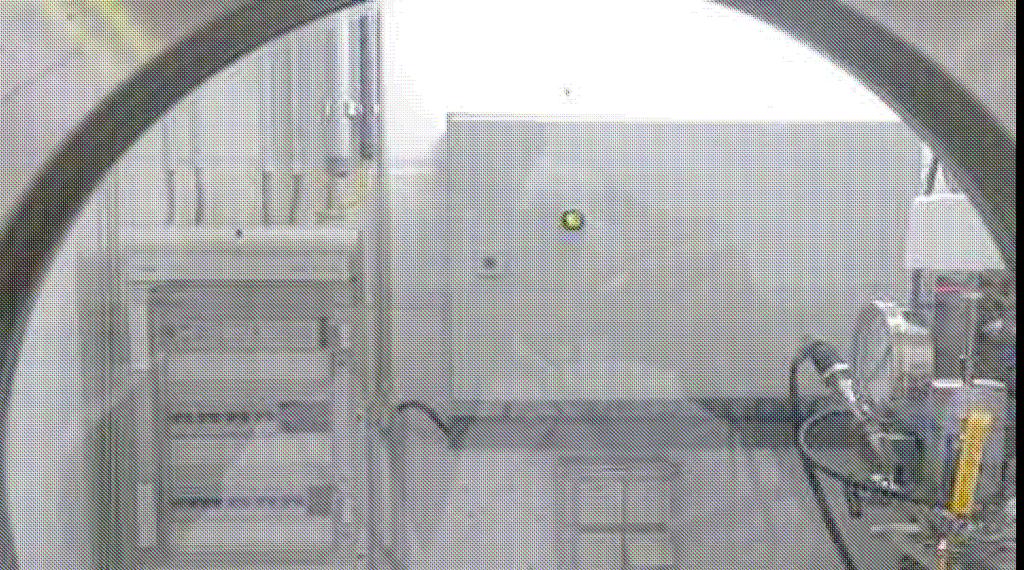
7 2. Degradation Test Rig
8 2. Degradation Test Rig Elements: 1. Reactor 2. Gas supply 3. Water balance 4. Gas flow 5. DTR control panel
9 2. Degradation Test Rig 1. Reactor


10 2. Degradation Test Rig 1. Reactor - Parr reactor ml - Max temperature : 500 C - Max pressure: 200 bar - T316 Stainless Steel - Heating mantle controls the temperature - Agitation rate is set by the operator 10

11 2. Degradation Test Rig


12 2. Degradation Test Rig Hollow shaft for a better gas-liquid contact
13 2. Degradation Test Rig 2. Gas supply
14 2. Degradation Test Rig 2. Gas supply - N 2 - CO 2 - O 2 - Compressed Air - Bottle Rack - Pressure regulator - Risk indications

15 2. Degradation Test Rig 2. Gas supply - Pressure transducers - Security valves - Filters - Mass flow controllers - Check valves - Valve for air pruge
16 2. Degradation Test Rig 3. Water balance

17 2. Degradation Test Rig 3. Water Balance: Saturator - Tank filled with destillated water - Saturation of the inlet gas with water - Water temperature controled from 25 C to 70 C - Gas pressure up to 25bar

18 2. Degradation Test Rig 3. Water balance: Condenser - Reactor outlet gas flows into the intern tube; cooling water flows into the mantle (extern tube) - Temperature controled from 20 C to 70 C - Condensat sampling possible
19 2. Degradation Test Rig 4. Gas flow

20 2. Degradation Test Rig 4. Gas flow - To the reactor via the saturator - Then to the FTIR analyser or to the atmosphere Gas Supply FTIR Reactor FTIR Atmosphere - Possibility of diluting the gas sample with N 2

21 2. Degradation Test Rig 4. Gas flow - Biphasic Coriolis flow meter - Back pressure regulation - Heating rope to prevent the gas flow from condensing in the tubing

22 2. Degradation Test Rig 4. Gas flow - Gas release to the atmosphere - Ventilated local to prevent any incident - Relief valves and FTIR exhaust are redirected to the atmosphere as well
23 2. Degradation Test Rig 5. Control panel


24 2. Degradation Test Rig 5. Control Panel Labview - Data acquisition (Pressures, Temperatures, Mass flows) - Control of the installation (Mass flow, heating elements, compressed air for security valves) 22nd August 2011

25 2. Degradation Test Rig 5. Control Panel Labview control panel - Data acquisition - Regulation

26 2. Degradation Test Rig 5. Control Panel Reactor controller - Temperature control - Agitation rate control - Pressure display - High temperature and pressure security

27 2. Degradation Test Rig 5. DTR Control Panel - Data acquisition - Regulation
28 2. Degradation Test Rig: Risk analysis Risk analysis - Deparis method: «Dépistage Participatif des Risques» - Electrical risks, explosions, gas and liquid leakages, chemicals contamination, fire, earthquake have all been envisaged. - Risk analysis reviewed by the prevention expert at Laborelec as well as at the University of Liège. - Emergency procedure has been detailed and software alarms have been implemented


29 2. Degradation Test Rig: Risk analysis Some performed improvements
30 3. Results of performed experiments

31 3. Results of performed experiments Results of the first experiments performed
32 3. Results of performed experiments Degradation profile over 14 days 33,00 30,00 Concentration (wt-%) 27,00 24,00 21,00 18,00 15,00 12, Day
33 3. Results of performed experiments
34 3. Results of performed experiments First conclusions: - Two weeks degradation gives better results - High temperature enhances the degradation - High oxygen-content enhances the degradation - Last experiments still have to be analysed - HPLC method is sufficient for following the MEA concentration, but seems very imprecise for screening degradation compounds
35 3. Results of performed experiments
36 4. Analytical methods


37 4. Analytical methods Liquid sample => High Pressure Liquid Chromatography => Gas Chromatography- Flamme Ionization Detector Gas Sample: => Fourier Transformed Infra Red Spectrometer
38 4. Analytical methods: HPLC HPLC: - Influences of eluent, salt concentration, ph, temperature, flow rate have been studied quite unsuccessfully. For more details see progress report, June A new column is beeing tested.
39 4. Analytical methods: HPLC Degraded MEA, Eluent 75:25 ACN:Buffer (NH4Ac 24mM ph 3.8); Mass flow 1.2ml/min; T=30 C, 215nm
40 4. Analytical methods: GC-FID - GC-FID: First results seem very promising, repetability has been demonstrated
41 4. Analytical methods: GC-FID Standard solution (MEA, AEAE, HEA, EDA) 1:
42 4. Analytical methods: GC-FID Degraded MEA (dil 1:100 in water)
43 4. Analytical methods: FTIR Gas phase analysis: gas calibration : CO 2 CO2
44 4. Analytical methods: FTIR NH3 calibration ( cm -1, cm -1 )
45 4. Analytical methods: FTIR MEA calibration ( cm -1, cm -1 )

46 4. Analytical methods: ion analysis Corrosion is followed thanks to this analysis
47 5. Conclusion

48 5. Conclusion Degradation test rig has been constructed Experiments are running Development of analytical methods in process
49 5. Conclusion Making the link between simulation and degradation => Objective: - having a reliable simulation model - taking solvent degradation into account - that can be used for predicting the most appropriated operating conditions for post-combustion capture Multi-objectives process optimization: - Energy savings (costs) - Solvent savings (lower solvent make-up) - Lower environmental impact due to solvent degradation
50 Thank you for your attention! Questions are welcome!