Güssing: Small scale gasification-ft
|
|
|
- Coleen Bradford
- 5 years ago
- Views:
Transcription


1 Güssing: Small scale gasification-ft Dr. Reinhard Rauch Vienna, University of Technology Bioenergy


2 Technology for People Institute of Chemical Engineering


3 166_3 Chemical Process Engineering & Energy Technology Future Energy Technology Reaction Engineeríng & Combustion Fluidized Bed Systems and Refinery Technology Biomass gasification and gas cleaning Synthetic biofuels BioFiT, BioSNG CO 2 separation processes Chemical Looping Combustion Recovery of minerals, metals and plant nutrients from incineration residues High temperature process engineering Fluidized bed conversion - IEA Operation of FCC pilot plant Catalyst testing Bio fuels from cracking of bio oils Adsorber optimization of vapour recovery units

4 New design of gasifier: G Volution Gasification zone Combustion zone no more limit in scaling-up, as there is no stationary fluidized bed anymore excellent gas-solids contact between catalytic bed material and product gas, so lower tar content increases of residence times for fuel particles as well as gases with regard to gas-solids interaction solids residence time distribution resembles a cascade of stirred vessels (dispersed downward movement of solids) 100 kw pilot plant at Vienna, University of Technology is in operation

5 BIOENERGY2020+


6 BE2020: 3 locations + 2 research sites 15 years of experience Pinkafeld Tulln Wieselburg Güssing Graz
7 Field of competences Scientific Coord.: H. Hofbauer CEO: W. Haslinger, R. Schmid Area 4: Cross cutting topics Sub Area 4.1: Sustainable supply and value chains AM: C Strasser, KR: P Schwarzbauer Sub Area 4.2: Automation and control AM: M Gölles, KR: C Hochenauer, SA: M Horn Area 1: Biomass combustion systems AM: A Weissinger KR: C Hochenauer SA: C Schmidl Sub Area 4.3: Modeling and simulation AM: R. Mehrabian Bardar, KR: C Hochenauer, SA: R Scharler Area 2: Biomass gasification systems AM: R Rauch KR: H Hofbauer Area 3: Bioconversion and biogas systems AM: G Drosg KR: W Fuchs Infrastructure: Lab services: Head: N Kienzl AM.. Area Manager KR.. Key Researcher SA.. Scientific Advisor


 Hybrid")
8 Area 2 Biomass Gasification Systems Increase of resource basis including biogeneous residues Biomass for industrial applications, e.g. substitution of natural gas Syngas-platform for bio-refineries Plants with poly-generation (heat, electricity, fuel) Hybrid systems with other RE Slide 8
9 The basic concept Green Chemistry Over 80,000 hours Producer Gas (gas engine, gas turbine, fuel cell) Synthetic Natural Gas (SNG) Biomass Biomass Gasification Hydrogen Mixed alkohols Oxosynthesis for aldehydes FT-Fuels (FT-Diesel) Synthesis gas H 2 + CO Isosynthesis for Isobutane Methanol / DME others Ammonia 9
10 Aviation fuels According to ASTM D Standard Specification for Aviation Turbine Fuel Containing Synthesized Hydrocarbons the following hydrocarbons can be blended into kerosene: A1. FISCHER-TROPSCH HYDROPROCESSED SYNTHESIZED PARAFFINIC KEROSINE A2. SYNTHESIZED PARAFFINIC KEROSINE FROM HYDROPROCESSED ESTERS AND FATTY ACIDS A3. SYNTHESIZED ISO-PARAFFINS FROM HYDROPROCESSED FERMENTED SUGARS A4. SYNTHESIZED KEROSINE WITH AROMATICS DERIVED BY ALKYLATION OF LIGHT AROMATICS FROM NONPETROLEUM SOURCES A5. ALCOHOL-TO-JET SYNTHETIC PARAFFINIC KEROSENE (ATJ-SPK) 10


11 GreenFly R&D project on kerosene from biomass, with focus on usage in Wankel engine Funded by: TAKE OFF Call,


 Purge Gas Wax Steam FT- fuels")
12 Synthetic Biofuels (FT- Route) Cellulose Hemicellulose Lignin Wood Chips Gasification Raw Syngas Cleaning/ Conditioning Pure Syngas H 2 /CO= 2 FT- Synthesis Fossil Products (e.g. LGO, HGO, VGO) FT- wax Hydro- (Co)-Processing i/n- paraffins (hydrocarbons) Purge Gas Wax Steam FT- fuels (diesel) Hydrogen (pure/ recycled) HPFT- Fuels (diesel+ kerosene)
13 DFB gasifier Steam gasification, so product gas with high quality (low nitrogen, optimal H 2 :CO ratio) can be produced, without need for pure oxygen Synthesis gas applications can be realised at smaller scale ( MW fuel )
14 Experimental work Biomass CHP Güssing To FT synthesis 14
15 Location Dual Fluid Gasifiers Usage / Product Fuel / Product MW, MW Güssing, AT Gas engine 8.0 fuel / 2.0 el 2002 Oberwart, AT Gas engine / ORC / H fuel / 2.8 el 2008 Villach, AT Gas engine 15 fuel / 3.7 el 2010 Senden/Ulm, DE Gas engine / ORC Burgeis, IT Gas engine 2 fuel / 0.5 el 2012 Göteborg, Sweden Folie 15 Start up Supplier Status AE&E, Repotec Ortner Anlagenbau Ortner Anlagenbau Operational Maintenance On hold 14 fuel / 5 el 2011 Repotec Operational BioSNG 32 fuel /20 BioSNG 2013 Repotec, RevoGas Repotec/ Metso On hold Operational California R&D 1 MW fuel 2013 GREG Operational Gaya, France BioSNG R&D 0,5 MW fuel 2016 Repotec Thailand Gas engine 4 fuel / 1 el 2016 GREG Under construction Under construction
16 Synthetic Biofuels (FT- Route) Cellulose Hemicellulose Lignin Wood Chips Gasification Raw Syngas Cleaning/ Conditioning Pure Syngas H 2 /CO= 2 FT- Synthesis Fossil Products (e.g. LGO, HGO, VGO) FT- wax Hydro- (Co)-Processing i/n- paraffins (hydrocarbons) Purge Gas Wax Steam FT- fuels (diesel) Hydrogen (pure/ recycled) HPFT- Fuels (diesel+ kerosene)

17 FT lab scale plant In operation since kg/day of FT raw product Slurry reactor, because of excellent heat transfer and easy scaling up Gas treatment removes Sulphur to below 10ppb Cobalt and Iron- based catalyst were tested Fully automatic 17


 (1 log")
18 Product Distribution and Hydrocarbons Content W n n(1 ) 2 n 1 log W n n nlog( ) (1 log ) 2 Folie 18
19 Synthetic Biofuels (FT- Route) Cellulose Hemicellulose Lignin Wood Chips Gasification Raw Syngas Cleaning/ Conditioning Pure Syngas H 2 /CO= 2 FT- Synthesis Fossil Products (e.g. LGO, HGO, VGO) FT- wax Hydro- (Co)-Processing i/n- paraffins (hydrocarbons) Purge Gas Wax Steam FT- fuels (diesel) Hydrogen (pure/ recycled) HPFT- Fuels (diesel+ kerosene)

20 Properties of FT Wax Carbon range Melting range Density at 130 C Viscosity at 130 C C/H/O C25 C105 ~ C kg/dm³ 6.62 mm²/s 85/14.7/0.3 %wt. 20

21 Conversion of FT wax Hydroprocessing Hydrocracking and hydroisomerisation in presence of catalyst and high pressure hydrogen atmosphere Used for removal of sulphur and nitrogen in almost every refinery Fluid Catalytic Cracking Standard unit in refinery for conversion of vacuum gas oil to olefins and gasoline 21

22 Results HP catalyst B 22
23 Economics Fossil Products (e.g. LGO, HGO, VGO) Wood Chips Gasification Raw Syngas Cleaning/ Conditioning Pure Syngas H 2 /CO= 2 FT- Synthesis FT- wax Hydro- (Co)-Processing Purge Gas Wax Steam FT- fuels (diesel) Hydrogen (pure/ recycled) HPFT- Fuels (diesel+ kerosene)
 Waxes: valuable chemicals, where a market already")
24 FT raw prooduct Value of raw FT products: Naphtha: worse than gasoline (~ EUR/t) Diesel: excellent quality, competes with NextBTL on the market (~ EUR/t) Waxes: valuable chemicals, where a market already exists 24

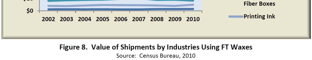
25 Market of Waxes 25


26 Prices of Waxes Why should anyone convert a high value product into a cheap product having in addition conversion losses? 26
27 Results Kerosene Waxes can be converted to kerosene with a conversion efficiency of about 20-50% (boiling range C) Cold flow behaviour in the range of -30 to -60 C freezing point (-40 C is the limit of ASTM) Most samples of kerosene fulfils ASTM D7566, Annex A1 for F-T SPK* (F-T SPK have been approved as maximum 50% blend stock in jet fuel) On Hydroprocessing more catalysts with different isomerisation behaviour should be tested *Synthetic Paraffinic Kerosene 27
28 BIOMASS-TO TO-FISCHER-TROPSCH nco + 2nH 2 = nch 2 + nh 2 O Folie 28

29 Work planed 1 barrel/day Economic optimisation of gas treatment Scaling up of Slurry FT reactor Long term tests fo FT synthesis with wood based synthesis gas Upgrading of the raw FT products Testing of FT products Folie 29


30 COMET project 1bpd Scientific partners Industrial partners Bilfinger Bohr- und Rohrtechnik GmbH Folie 30
31 The actual reactor setup in the pilot plant What is our aim? o o o o One through flow without recycling of offgas. Ratio height diameter H/D 20. Coupled heating devices. Conical gas distributor geometry. o Project of different flow configurations: o o o One Through Flow With Recycling of Offgas Recycling + Steam Reforming o Height/Diameter 7. o Integration of a heating exchanger system. o Flat gas distributor geometry. Folie 31