Fourth Edition October Michigan Department of Environmental Quality. Water Bureau
|
|
|
- Joella Haynes
- 5 years ago
- Views:
Transcription
1 Cross Connection Rules Manual Fourth Edition October 2008 Michigan Department of Environmental Quality Water Bureau Jennifer M. Granholm, Governor Steven E. Chester, Director
2 MICHIGAN DEPARTMENT OF ENVIRONMENTAL QUALITY WATER BUREAU 525 WEST ALLEGAN STREET P.O. BOX LANSING, MICHIGAN The Michigan Department of Environmental Quality (DEQ) will not discriminate against any individual or group on the basis of race, sex, religion, age, national origin, color, martial status, disability, or political beliefs. Questions or concerns should be directed to the DEQ Office of Personnel Services, P.O. Box 30473, Lansing, MI 48909
3 CROSS CONNECTION RULES MANUAL FOURTH EDITION October 2008 Michigan Department of Environmental Quality Water Bureau 525 West Allegan Street Post Office Box Lansing, Michigan
4 ACKNOWLEDGEMENTS The department wishes to thank the United States Environmental Protection Agency for permission to use some of the illustrations from their Cross Connection Control Manual. The department would also like to thank the following individuals for their assistance and expertise in the rewriting of this manual. Matt Kapcia City of Troy Mike Lueck Mid-West Instrument Mike Smith Grand Traverse County Barry Walter HydroDesigns, Inc. (i)
5 FOREWORD 4th EDITION In the water supply field, a considerable amount of attention is being focused nationally on new drinking water standards, source water protection and enhanced treatment. However, water supply professionals must remain vigilant in their efforts to protect the integrity of the potable water after it enters the distribution system. The continued expansion of public water distribution systems in Michigan has resulted in thousands of additional service connections annually. Therefore, cross connection control remains a critical link in protecting public health by maintaining the quality of drinking water from the source, through the distribution system and to the customers. Drinking water quality will be jeopardized without a persistent effort in cross connection control, regardless of efforts to protect the source of supply and improved treatment techniques. This manual strives to educate water system operators, plumbers, contractors and any others in the industry about the need for effective cross connection control. Acronym Key Act 399 Michigan Safe Drinking Water Act, 1976 PA 399, as Amended, and the Administrative Rules ASSE American Society of Sanitary Engineering AVB Atmospheric Vacuum Breaker CSA Canadian Standards Association DCVA Double Check Valve Assembly DEQ Department of Environmental Quality DLEG Department of Labor and Economic Growth HBVB Hose Bib Vacuum Breaker MPC Michigan Plumbing Code PVB Pressure Vacuum Breaker RPZ Reduced Pressure Principle Backflow Assembly (ii)
6 WATER SUPPLY CROSS CONNECTION RULES MANUAL (Incorporated by the Water Bureau as a Supplement to Part 14 of the Administrative Rules under the Michigan Safe Drinking Water Act) TABLE OF CONTENTS Page Number Chapter 1 Introduction 1 Chapter 2 Water Supply Cross Connection Rules 3 Chapter 3 Cross Connection Terminology... 6 Chapter 4 Backflow Prevention Devices. 11 Chapter 5 Hazards Chapter 6 Common Hazards Chapter 7 Common Facilities To Inspect Chapter 8 Responsibilities Chapter 9 Local Cross Connection Control Program Chapter 10 Containment, Isolation and Piping Identification Chapter 11 Acceptable Means of Protection.. 47 Chapter 12 Customers To Inspect Chapter 13 Reinspection Appendix A - Suggested Model Ordinance Appendix B - Cross Connection Control Program (CCCP) Guidance Outline Appendix C - Model Cross Connection Control Programs Appendix D - Sample Record Keeping Forms Appendix E - Backflow Assembly Test Procedures Appendix F - Sample Letters Appendix G - Approved Backflow Preventers (iii)
7 Chapter 1 - INTRODUCTION A cross connection is a connection or arrangement of piping or appurtenances through which backflow of nonpotable water could flow into the public drinking water supply. Historically, the waterworks industry has made a determined effort to provide the consumer with an unlimited quantity of high quality water. Much of this effort has been concentrated on the production of quality treated water with insufficient attention paid to protecting the quality of the water within the distribution system. Inappropriate connections between piping containing contaminants or potential contaminants and potable water supply piping are encountered on all public water supply distribution systems. The control of these cross connections is difficult since it demands the inspection and necessary reinspection of industrial and commercial establishments, as well as some control of public and private dwellings, including homes. Too often total reliance has been placed on producing safe water and attempting to maintain adequate pressure at all times throughout the distribution system. While these efforts are of extreme importance, they have not proved to be entirely effective in protecting water quality within the distribution system. It is essential that all cross connections on the public water supply distribution system be removed in order to protect water quality when system pressures are less than adequate to prevent backflow. The water supply cross connection rules define cross connection as, "a connection or arrangement of piping or appurtenances through which a backflow could occur." In turn, backflow means, "water of questionable quality, wastes or other contaminants entering a public water supply system due to a reversal of flow." By definition then, the term backflow includes situations caused by either backpressure or backsiphonage. Since passage of the cross connection control rules in April of 1972, much effort has been spent by many Michigan water utilities to maintain an effective cross connection control program. Unfortunately, despite the best efforts of these water utilities, there continues to be documented cases in Michigan (as well as the United States) where nonpotable water or contaminants have entered the potable piping system via a cross connection. In Michigan, there have been past cases where ammonia refrigerant, malathion, propylene glycol, soap from a car wash and even brucellosis culture have backflowed into public distribution systems through unprotected cross connections. Therefore, water system personnel must continue to eliminate and prevent any cross connections with the public water supply system. It is estimated that 90% of the incidents of backflow through cross connections are either unreported or unnoticed. Historically, an effort has been made to protect public water supplies from backflow by maintaining adequate pressure on the distribution system. The distribution system and onsite piping must be adequately sized to provide fire flows without serious loss of pressure if we are to be successful in protecting against backflow even with an ongoing cross connection control program. The design of the distribution system, including factors such as main placement and sizing, valving, and storage, is of extreme importance in protecting against backflow conditions. 1
8 This manual is meant to serve as a guideline for water utilities to follow when implementing a local cross connection control program. There are many situations one may encounter when making inspections where a clear cut solution is not possible or when corrective action is not popular. The utility must keep in mind that when seeking a solution to a particular problem the public health of its customers is at stake. Consultation with representatives from the Michigan Department of Environmental Quality is recommended before final decisions are reached on unusual cases. It may be necessary for department staff to make an on-site inspection in order to render a fair and effective decision. 2
9 Chapter 2 - WATER SUPPLY CROSS CONNECTION RULES Part 14 of the Michigan Safe Drinking Water Act, 1976 PA 399, as amended, (Act 399) and the Administrative Rules contain the cross connection rules that public water systems must follow regarding cross connection control. There are seven rules in Part 14 (Rules ) that are listed below in their entirety. R Definitions Rule As used in this part: (a) "Backflow" means water of questionable quality, wastes, or other contaminants entering a public water supply system due to a reversal of flow. (b) "Cross connection" means a connection or arrangement of piping or appurtenances through which a backflow could occur. (c) "Safe air gap" means the minimum distance of a water inlet or opening above the maximum high water level or overflow rim in a fixture, device, or container to which public water is furnished which shall be at least 2 times the inside diameter of the water inlet pipe, but shall not be less than 1 inch and need not be more than 12 inches. (d) "Secondary water supply" means a water supply system maintained in addition to a municipal type public water supply, including but not limited to water systems from ground or surface sources not meeting the requirements of Act No. 98 of the Public Acts of 1913, as amended, being sections to of the Compiled Laws of 1948, or water from a public water supply which in any way has been treated, processed, or exposed to any possible contaminant or stored in other than an approved storage facility. (e) "Submerged inlet" means a water pipe or extension thereto from a public water supply terminating in a tank, vessel, fixture, or appliance which may contain water of questionable quality, waste, or other contaminant and which is unprotected against backflow. (f) "Water utility" means a governmental unit, municipal or private corporation, association, partnership, or individual engaged in furnishing water to the public for household or drinking purposes. R Compliance with regulations and local codes. Rule A connection with a public water supply system shall comply with existing laws, ordinances, and rules including: (a) Act No. 266 of the Public Acts of 1929, as amended, being sections to of the Michigan Compiled Laws. (b) Local ordinances or rules providing acceptable protection against cross connections. 3
10 R Cross connections prohibited. Rule (1) A cross connection shall not be made between a public water supply system and a secondary water supply. (2) A cross connection shall not be made by submerged inlet. (3) A cross connection shall not be made between a public water supply and piping which may contain sanitary waste or a chemical contaminant. (4) A cross connection shall not be made between a public water supply system and piping immersed in a tank or vessel which may contain a contaminant. R Local cross connection control programs. Rule (1) A water utility shall develop a comprehensive control program for the elimination and prevention of all cross connections. The plan for the program shall be submitted to the department of environmental quality for review and approval within one year after the effective date of these rules. When the plan is approved, the water supply shall implement the program for removal of all existing cross connections and prevention of all future cross connections. (2) The program shall include but not be limited to: (a) A complete description of the method of administering the program, including the designation of inspection and enforcement agency or agencies. The local authority for implementation of the program shall be indicated, preferably by ordinance. (b) A time schedule for inspection and reinspection of all water utility customers' premises for possible cross connections. The periodic reinspection shall be used to ascertain whether or not safe air gaps or required protective devices are in place and in working order. (c) A description of the methods and devices (as approved by the department of environmental quality) used to protect the public water supply. R Corrections and protective devices. Rule (1) A user of public water shall obtain written approval by the water utility or authorized inspection agency of any proposed corrective action or protective device before using or installing it. (2) The total time allowed for completion of the necessary corrections shall be contingent upon the degree of hazard involved and include the time required to obtain and install equipment. If the cross connection has not been removed, after a reasonable period of time, the water utility shall physically separate the public water supply from the on-site piping system in such a manner that the two systems cannot again be connected by any unauthorized person. 4
11 (3) A water utility shall report annually to the department of environmental quality on the status of the cross connection control program on a form provided by the department. R Piping identification. Rule When a secondary water source is used in addition to a public water supply system, exposed public water and secondary water piping shall be identified by distinguishing colors or tags and so maintained that each pipe may be traced readily in its entirety. If piping is so installed that it is impossible to trace it in its entirety, it will be necessary to protect the public water supply at the service connection in a manner acceptable to the department of environmental quality. R Private water storage tanks. Rule A private water storage tank supplied from a public water supply system shall be deemed a secondary water supply unless it is designed and approved for potable water usage. 5
12 Chapter 3 - CROSS CONNECTION TERMNIOLOGY Act 399 defines a cross connection as a connection or arrangement of piping or appurtenances through which backflow could occur. A cross connection can be any temporary or permanent connection between a public water system or consumer s potable water system and any source or system containing nonpotable or contaminated water, or other substances. Backflow is defined in Act 399 as water of questionable quality, wastes, or other contaminants entering a public water supply system due to a reversal of flow. Whenever there is a physical connection between a potable water system and a nonpotable environment, backflow may occur from backsiphonage or backpressure. The following pages will explain and illustrate both backsiphonage and backpressure. Backsiphonage is backflow caused by negative or reduced pressure in the supply piping when there is a drop in water system pressure due to a water main break, hydrant flushing or nearby fire fighting. The effect on flow is similar to sipping water through a straw. Figure 3-1 shows how water main pressure is affected if water is withdrawn from a pipe at a very high rate. If the hydrant at point F is opened and the valve at point G is closed, the flow path to the hydrant is restricted and the water pressure at the hydrant drops to zero. If the facilities at points B, C, and D are above the hydraulic grade line, the water in the lines within those facilities will flow towards the lower pressure created by the open hydrant at point F. This condition has the potential to be a very serious public health threat if there are any unprotected cross connections within those facilities. Figure 3-1 6
13 The backsiphonage shown in Figure 3-2 is the result of reduced water system pressure on the suction side of an online booster pump. The booster pump supplying the upper floors creates a reduced pressure situation upstream or on the suction side of the pump. This reduced pressure creates a backsiphonage condition in the lower floors, drawing contaminated water from the dishwasher to the suction line of the booster pump. Figure 3-2 7
14 Figure 3-3 shows how backsiphonage can occur when a distribution system is shut down for repair. When the valves on each side of the break are closed, negative or reduced pressure will occur at all locations within the building that are at a higher elevation than the break. As a result of the negative pressure within the building plumbing, contaminated water is drawn from the bathtub toward the main. In these repair situations, several blocks of homes, businesses or commercials establishments can be affected. Figure 3-3 8
15 Backpressure is backflow caused by a downstream pressure that is greater than the upstream or supply pressure in a public water system. Backpressure can result from an increase in the downstream pressure created by pumps, boilers, elevation differences, and air or steam pressure to name a few. There is a high risk that nonpotable water may be forced into the potable water system if these interconnections are not properly protected. Figure 3-4 shows how a pump installed on a customer s piping system can increase the pressure to a point where it exceeds the water main pressure, causing a backflow condition. Many large boats or ships flush their fire fighting or wastewater tanks by connecting them to the dockside potable water system. As shown on the graph, the pressure in the main is 100 psi and 75 psi as it enters the boat s system. If the onboard fire fighting pump (rated at 200 psi) is operated while the valve at point A is left open, the pressure created by the pump, which is higher than the main pressure, forces contaminated water into the dockside and public systems. Figure 3-4 9
16 In many buildings, potable water is used as a source of water for boilers. A boiler is a closed vessel in which water or other fluids is heated under pressure. The fluid is then circulated out of the boiler for use in various processes or heating applications. The pressures within boilers can become much greater than the system pressure at the point of connection. In many cases, chemicals of varying toxicity are added to boilers to reduce corrosion or scaling. Since boilers can cause backflow by backpressure, it is necessary to protect the water supply by installing a backflow assembly on the makeup or feed line to the boiler as noted in Figure 3-5. Figure

17 Chapter 4 - BACKFLOW PREVENTION ASSEMBLIES and DEVICES This chapter outlines the various assemblies and devices used for protection against cross connections. Specific installation requirements and/or use restrictions apply to some of these assemblies and devices or methods of protection. 4.1 Air Gap Separation "Safe air gap" is defined as, "the minimum distance of a water inlet or opening above the maximum high water level or overflow rim in a fixture, device, or container to which public water is furnished which shall be at least two times the inside diameter of the water inlet pipe, but shall not be less than one inch and need not be more than 12 inches." Figure 4-1 shows safe air gap arrangements for makeup tanks, sinks and drain lines. Note: Air gaps must be twice the diameter of the inlet pipe, at least 1, but no greater than 12. Figure
18 Air gaps have proven to be an effective method of protecting against backsiphonage in common household installations such as sinks, bathtubs, washers, and water softeners as well as hazardous industrial applications. Air gaps are not testable but need to be inspected from time to time to make certain that someone has not altered the plumbing. For other users and other types of cross connections, an air gap is generally not practical. Air gaps on in-plant problems have proven to be unacceptable, particularly where high water pressure is required or where splashing cannot be tolerated. Examples of such installations would be hospital and pathology laboratories, mortuary tables and sinks, research (bacteriologic and/or chemical) laboratories, plating tanks, and wash and rinse tanks. 4.2 Reduced Pressure Principle Backflow Assemblies (RPZ) The reduced pressure principle backflow assembly (abbreviated in this manual as RPZ for reduced pressure zone ) consists of two independently acting, spring loaded check valves with a relief valve placed between the two check valves designed to prevent the backflow of water. These units are located between two resilient-seated shutoff valves and are equipped with test cocks to form an assembly as shown in Figure 4-2. RPZs are testable assemblies and must be tested at regular frequencies. Figure 4-2 Figure 4-3 illustrates the principles of operation of a RPZ. The pressure in zone 1 is maintained at the same pressure as the public water supply system. As the water passes through check valve No. 1 into zone 2, the pressure within zone 2 is less due to the headloss occurred by passing through the check valve. The water then passes through check valve No. 2 into zone 3 with the pressure again reduced. The valve located at the differential pressure relief port is normally held in a closed position since the pressure in zone 1 is higher than in zone 2. The pressure differential maintains a 2 psi residual pressure on the spring loaded relief valve. Thus, if the water pressure in zone 2 plus the 2 psi residual spring loaded pressure on the relief valve becomes greater than the pressure in zone 1, the differential pressure relief valve opens and water is discharged through the relief port to the atmosphere. 12


19 To function as designed, the relief port must have a free discharge at the drain port and the discharge must be visible. If it is necessary to pipe any discharge to another area, it may be accomplished by a free discharge through a visible air gap into a collection device such as a funnel, with gravity flow to discharge at a more desirable point. Figure 4-3 Figure 4-4 shows a typical RPZ under normal operating conditions. Figure
.")

20 If the pressure within the public water supply system becomes less than the downstream system pressure, the normal direction of flow through the RPZ would tend to reverse. If the second check valve properly seats, the reversal of flow will be stopped at that point (Figure 4-5). Figure 4-5 However, if the second check valve fails to seat properly during reversal of flow situations, water will be discharged through the relief valve (Figure 4-6). Figure 4-6 Customers having to install a RPZ need to be aware of the additional headloss that will be created when one is installed. Depending upon the design of the internal piping system, it may be possible to isolate certain critical areas with such an assembly lessening the overall impact of reduced pressures. An example of such an installation would be a bay of plating tanks, particularly if fed by only one service line. 14
21 When properly installed and maintained, a RPZ will provide adequate protection for the public water supply system from either backpressure or backsiphonage backflow. Since the RPZ has a drain port between the two spring loaded check valves, it must be installed in a location not subject to flooding. It also must be protected from adverse weather conditions because the diaphragm, which is a part of the relief valve, could be damaged by freezing. Care must be taken to install these assemblies in accordance with manufacturers recommendations. Maintenance is necessary for any mechanical equipment if we are to rely upon it to function properly when needed. Therefore, any RPZ must be installed in a location where they are accessible for routine inspection, testing, and repair. These assemblies are mechanical in nature and subject to breakdown, and they must be isolated during periods of inspection and repair. If there is only one service line from the public system and if water service is required 100% of the time, it will be necessary to install a second RPZ in parallel with the proper valving to provide for an uninterrupted, continuously protected supply. 4.3 Vacuum Breakers Vacuum breakers are among the simplest and least expensive types of mechanical backflow preventers. There are two types of vacuum breakers: atmospheric and pressure. When properly installed, they provide excellent protection against backsiphonage. Vacuum breakers cannot be used to protect against backpressure. Properly installed vacuum breakers will provide adequate protection for individual toilets, urinals, laboratory sinks and lawn sprinkling systems. Vacuum breakers installed to protect against backsiphonage on lawn sprinkling systems must be full sized (pipe size) and at least 6 inches above the highest sprinkler head. On large lawn sprinkler systems and distribution lines serving them, it may be acceptable to install two or more vacuum breakers in parallel. The following are general installation requirements for vacuum breakers: Must be installed in a vertical position. Shall be installed in line and be the same size of the supply piping. Must be installed a minimum of 6-inches above all downstream piping and the highest outlet or flood level rim. Shall not be installed in areas where spillage is a concern (unless it is spill resistant type). Shall not be installed in a vent hood or other areas where toxic or other fumes are present. 15


22 4.3.1 Atmospheric Vacuum Breakers (AVB) An AVB allows air to enter the water supply line when the pressure in the public system or the service line is reduced to zero or below. During normal flow, a float within the device is pushed up and seals the air inlet. When a backsiphonage condition develops, the float drops and allows air to enter through the air inlet, preventing backsiphonage. Figure 4.7 shows an AVB under normal and no flow conditions plus a typical installation. AVBs are considered nontestable devices. Figure 4-7 AVBs shall not be installed where they will be under continuous pressure for more than 12 hours (i.e. no downstream shutoff valve). 16

23 4.3.2 Hose Bib Vacuum Breakers (HBVB) HBVB are small devices that are similar to AVBs. They consist of a spring loaded check valve that is normally in the closed position, and a vent, that is normally in the open position. When the device is pressurized, the check valve will open and the vent will close allowing water to flow through the device. Under a backsiphonage condition, the check valve will close and the vent will open allowing air into the system to prevent backsiphonage (Figure 4-8). Figure 4-8 HBVBs are typically attached to sill cocks that in turn are connected to garden hoses and spray outlets. They are also considered to be nontestable devices. 17
.")
24 4.3.3 Pressure Vacuum Breakers (PVB) This assembly is similar to an AVB, in that it prevents backsiphonage by allowing air in through a vent. The PVB consists of a spring loaded check valve, spring loaded air inlet valve, test cocks and two shutoff valves forming an assembly (Figure 4-9). Because of the spring loading, it can be installed where it will be under continuous pressure for long periods, i.e. be installed with a downstream shutoff valve (Figure 4-10). PVBs are testable assemblies and must be tested at regular frequencies. Spill resistant PVBs are available and are designed to minimize spillage from the device. Figure 4-9 Figure

25 4.4 Double Check Valve Assemblies (DCVA) DCVAs provide some degree of protection against backflow, but do not have the same failsafe relief port as an RPZ. Therefore, they may only be used to protect the public supply from aesthetic or nonhealth hazards. DCVAs are acceptable protection for low pressure untreated boilers and certain fire protection systems. A DCVA consists of two loaded check valves, test cocks and shutoff valves forming an assembly (Figure 4-11). They may be used under continuous pressure and protect against backflow from both backpressure and backsiphonage. They are testable assemblies and must be tested at regular frequencies. Figure 4-11 There are several other variations of DCVAs that are commonly found on water supply piping. They include: Double Check Detector Check used to protect the water supply from untreated fire protection systems. It has a bypass line which also has a DCVA and a water meter which measures very low fire line flows (Figure 4-12). Figure
.")
26 Double Check Valve with Intermediate vent used on ¼, ½: or ¾ pipes to protect against both backpressure and backsiphonage in low hazard situations. A vent located between the two check valves provides extra backflow protection (Figure 4-13). One type of device is specifically designed for carbonated beverage machines to prevent the backflow of carbon dioxide gas and carbonated water into the water supply. Figure
27 4.5 Barometric Loop When properly installed, a barometric loop as shown in Figure 4-14 will protect the public water supply system from backsiphonage. The top leg of the loop must be a minimum of 35 feet above the spill rim of the highest free water surface, because a perfect vacuum can only lift water approximately 34 feet. However, the DEQ recommends that a proper vacuum breaker be installed instead of a barometric loop. Figure 4-14 illustrates an acceptable barometric loop. The device must be properly designed, must be installed so that it is adequately protected against freezing, and must not be used in a position where it could possibly be subject to backpressure. Air lift is a potential problem and a check valve should be installed at the top of loop to break any possible flow. check valve 35 min water supply service overflow Figure 4-14 Barometric Loop 21
28 4.6 Approved Backflow Prevention Devices In addition to the list of approved devices located in Appendix G, the DEQ also recognizes all American Society of Sanitary Engineering (ASSE) approved devices for use in the State of Michigan. Please note that the appropriate ASSE Seal Authorization number must be stamped into the casting of the backflow preventer for it to be an approved device. ASSE Seal Authorization Numbers and Titles pertaining to backflow prevention are listed below. A listing of all ASSE approved devices may be found at #1001 Atmospheric Type Vacuum Breakers #1002 Anti-Siphon Fill Valves for Water Closet Tanks #1004 Backflow Prevention Requirements for Commercial Dishwashing Machines #1011 Hose Connection Vacuum Breakers #1012 Backflow Preventer with Intermediate Atmospheric Vent #1013 Reduced Pressure Principle Backflow Preventers and Reduced Pressure Fire Protection Principle Backflow Preventers #1015 Double Check Backflow Prevention Assemblies and Double Check Fire Protection Backflow Prevention Assemblies #1018 Trap Seal Primer Valves - Potable Water Supplied #1019 Vacuum Breaker Wall Hydrants, Freeze Resistant, Automatic Draining Type #1020 Pressure Vacuum Breaker Assemblies #1021 Drain Air Gaps for Domestic Dishwasher Applications #1022 Backflow Preventer for Beverage Dispensing Equipment #1024 Dual Check Valve Backflow Preventers #1032 Dual Check Valve Type Backflow Preventers for Carbonated Beverage Dispensers - Post Mix Type #1035 Laboratory Faucet Backflow Preventers #1044 Trap Seal Primer Devices - Drainage Types and Electronic Design Types #1047 Reduced Pressure Detector Fire Protection Backflow Prevention Assemblies #1048 Double Check Detector Fire Protection Backflow Prevention Assemblies #1052 Hose Connection Backflow Preventers #1053 Dual Check Backflow Preventer Wall Hydrants Freeze Resistance Type #1055 Chemical Dispensing Systems #1056 Spill Resistant Vacuum Breakers The DEQ will also accept backflow preventers approved by the Canadian Standards Association (CSA). The appropriate CSA standards for each type of backflow preventer can be found in the latest edition of the Michigan Plumbing Code. 22
29 4.7 Unapproved Devices or Methods The following is a brief discussion of methods which are not approved to protect against backflow. Single Check Valves even when installed in series, have not proven to be effective protection against the hazards of backflow and are not approved except in very limited fire protection installations as outlined later in this manual. Spool Connections are sections or pieces of pipe that can be easily removed and replaced to physically separate or connect potable piping to non potable piping. This type of protection against cross connections was once used in the past to separate the public supply from a secondary supply. This type of separation is not an acceptable form of protection and should be replaced by an approved backflow preventer. Swing Connections and 4-Ways Plug Valves were historically used to separate the public supply from a secondary supply. However, these devices or methods are no longer approved as an acceptable means of backflow protection. 4.8 Testing of Backflow Assemblies RPZs, PVBs and DCVAs are all testable backflow assemblies and must be tested by an approved tester at certain frequencies to ensure that they are in good working order. Any backflow preventer that is designed to be tested is considered an assembly, and all assemblies shall be tested at any of the following circumstances. 1. At time of installation or relocation. This includes reinstallation of seasonal assemblies that are taken out of service for a period of time and reinstalled. 2. After a repair. 3. At a frequency determined by the public water system in accordance with the approved local cross connection control program. Items No. 1 and No. 2 are required by the Michigan Plumbing Code. Item No. 3 is a required element of the local cross connection control program which must state how often backflow assemblies shall be tested. A 1991 Memorandum of Understanding between the DEQ and the Michigan Department of Labor and Economic Growth (DLEG) clarifies that public water supplies under the jurisdiction of Act 399 shall establish the frequency for testing of backflow assemblies in their respective service areas. Currently, all assemblies must be tested at least once every 5 years. However, effective January 1, 2011, the minimum frequency that backflow assemblies must be tested is going to be reduced from five (5) to three (3) years. All water systems must make certain that their approved cross connection control program reflects this change by
30 Local cross connection control programs may establish more frequent testing based on site specific conditions and the degree of hazard associated with any account. It is recommended that all high hazard situations and RPZs be tested annually. Any assembly that fails a test must be repaired and immediately retested by an approved/certified tester. 4.9 Approved/Certified Testers In an effort to achieve uniform testing throughout the state, certain requirements must be met for any person to test backflow assemblies. Approved testers are classified into one of the following categories: General tester is a person who holds a valid Michigan journey or master plumbing license and has passed an approved backflow tester class. General testers can test any assembly within any facility at any location. Restricted tester is not a licensed plumber, but has passed an approved backflow tester class. Restricted testers can only test within their own home or at their normal place of employment. Approved tester courses are conducted by the Michigan Plumbing and Mechanical Contractors Association, ASSE and several local plumbing unions. The courses have been sanctioned by the DLEG Plumbing Division, the State Plumbing Board, and the DEQ Water Bureau. These training courses are open to plumbing contractors, plumbing inspectors, and water utility personnel involved with cross connection control. Water systems shall only accept test results performed by certified testers and must verify on the test report form that the individual who conducted the testing is certified. Water system personnel should report to the State Plumbing Board any person who may be testing assemblies that is not approved to do so. The DEQ Water Bureau keeps a master list of all certified testers within the state. A list of certified testers organized by county may be obtained by contacting any DEQ District Office General Backflow Preventer Testing Requirements Water system personal should be familiar with the general testing requirements of backflow preventers. As mentioned in Chapter 4.8, testable assemblies must be tested upon installation, after a repair or relocation, or at the frequency specified by the public water system. Testing should be done in accordance with the procedures located in Appendix E or any nationally recognized test procedure. Any test procedure should only be used with prior approval of the local cross connection control administrator. 24
31 4.11 Test Report Forms Every supplier of water is encouraged to create a test form that can be used by testers to submit backflow preventer test results. When a notification letter is mailed to a building owner stating that their assemblies need to be tested, a test form should be enclosed for the tester to use during the test procedure. When test forms are received by the supplier of water, they must be carefully reviewed to make certain that the information on the form is accurate. Any test forms with incomplete or inaccurate information, including forms with no tester signature should not be accepted and returned to the owner. Test report forms should contain, but not be limited to, the following information: owner s name and mailing address building address type of device manufacturer s name, model number, serial number, and size of assembly physical location of assembly within the building (as descriptive as possible) description of application (i.e. equipment or system served) initial test results (pass-fail of first check and second check, relief valve discharge, air inlet opening, static line pressure) test gauge manufacturer, model number, serial number and last date of calibration repairs made, repair parts used, cleaning performed final test results, as applicable printed name, signature and certification number of the tester 4.12 Backflow Preventer Test Kit Accuracy The differential pressure gauge is the main working part of the backflow preventer test kit. With this gauge, the tester can determine if there are fouled check valves, test relief valve openings and accurately test the differential pressure zones. The test kit, including the gauge should be tested for accuracy annually by a company that is equipped to do such work. If the test kit is damaged via freezing or dropping, it should be tested for accuracy immediately. The test kit shall be accurate within a tolerance of psid at 5, 2 and 1 psid on descending pressure. 25
32 Chapter 5 - HAZARDS The degree of hazard posed by cross connections depends upon the type of potential contaminant and the likelihood for backflow to occur. This chapter will review and illustrate a variety of both backsiphonage and backpressure backflow conditions as well as some typical corrective measures. Part 14, Rule 1403 of the water supply cross connection rules specifically mentions various types of cross connections. A brief review follows: 5.1 A cross connection shall not be made between a public water supply system and a secondary water supply. Many industrial and commercial establishments as well as some private dwellings maintain a secondary source of water in addition to the public water supply. This rule makes it illegal to maintain a cross connection with any surface water or any well which is not under the control of the water utility. In an effort to conserve water, more industries and commercial establishments now utilize cooling towers and recirculation systems. Due to the design and normal operation of these cooling towers, it is possible that the water being recirculated is contaminated chemically or bacteriologically. Therefore, recirculated water systems are also considered secondary supplies. When reviewing onsite piping, critical pieces of equipment requiring a continuous supply of water should be identified, as they often have a secondary source. Furnaces, compressors, and some boilers may be in this category. As such, direct cross connections are likely to be found. To prevent the secondary source water from entering the public supply, it must either be physically separated from the potable water supply or a RPZ must be installed (see Figure 5-1). It is important that reinspections be routinely conducted to make certain these protective measures are not bypassed or circumvented. Figure

33 Fire systems at industries with secondary water supplies must be carefully reviewed to determine whether or not the two systems have been cross connected. If RPZs are being considered, the fire protection system must be designed to account for the resulting decrease in available pressure. Many facilities have onsite pumps which pump water from a nonpotable source to an internal piping system. In many cases, these pumps use potable water to prime the pump or to lubricate the bearings. These uses are also considered to be direct connections between the public supply and a secondary supply. That is why pumps for auxiliary systems, cooling systems, and fire systems must be inspected even if they are not interconnected to the potable system. For the same reason, pumps which recirculate water from cooling towers or substandard storage facilities must also be inspected. When a storage tank forms an integral part of an industrial or other onsite system, it may be necessary to consider it a secondary supply. If the storage facility does not meet public water system construction standards, is not properly maintained, or the water is treated in any way, appropriate protection is required. 5.2 A cross connection shall not be made by submerged inlet. Submerged inlets are serious potential hazards in public water supply distribution systems. These inlets can often be found in plating plants, hospitals, medical laboratories, nursing homes, mortuaries, photo laboratories, refrigeration systems and even private residences. Many of the potential contaminants that may backflow through submerged inlets will not discolor the water and would not be noticed until sickness or death occurred. Plating tanks, wash and rinse tanks, and similar installations in industrial establishments are potential sources of contamination since chemicals such as chromium, nickel, and cyanide are routinely in use. In some cases, facility managers have cooperated and removed water lines submerged in individual plating tanks. However, upon reinspection, utilities discovered the air gaps had been restored to a submerged condition without the knowledge of managers. The workers simply replaced the submerged inlets to avoid splashing or to provide for better mixing of the chemicals in the tank. Therefore, an air gap at individual plating tanks cannot be considered reliable protection. Vacuum breakers have also been used at submerged inlets to protect internal piping systems. Like air gaps, many of these devices have also been removed or altered in such a manner that the protection for the internal piping system is voided. Therefore, a second line of defense can be provided on the service line to the building or on the potable water line to the area of concern. This redundant protection is particularly important for customers with multiple submerged inlets or where reinspection may be difficult. 27

34 5.3 A cross connection shall not be made between a public water supply and piping which may contain sanitary waste or chemical contaminant. This type of situation would be encountered where a pipe or tank containing potable water is discharged to a sanitary sewer and could be subject to backflow or when the public system is connected directly to an industrial or commercial establishment where some chemical additives have been applied to the water supply. Boilers and steam systems would be included in this area. Fire fighting systems may contain water treated with an antifreeze chemical to prevent freezing. Certainly, toxic chemicals such as ethylene glycol (automobile antifreeze) shall NOT be used in this manner, but often there is no control over the use of such chemicals. Propylene glycol is a chemical which is nontoxic and can be used as antifreeze protection. However, it also must be maintained separate from the public system and the potable supply. In 1969, an incident at Holy Cross University occurred where water containing the hepatitis virus backflowed into the drinking water supply. This widely publicized incident illustrated the serious need to properly protect public systems from backsiphonage backflow from lawn irrigation systems. Backflow preventers must be properly selected and installed to prevent this from happening. 5.4 A cross connection shall not be made between a public water supply system and piping immersed in a tank or vessel which may contain contaminants. Water is often used as either a coolant or a source of heat in heat exchangers, cooling towers and other chemical processes. These systems usually require submerging water piping in various contaminants. Since the piping is subject to corrosion and leakage, the result is a potential submerged inlet depending upon the condition of the piping. Commercial laundries and associated heat reclamation facilities are another source of concern for this type of cross connection. 28

35 Chapter 6 - COMMON HAZARDS Many types of hazards that require cross connection protection are found in a variety of facilities. This chapter discusses common cross connection hazards a water utility may encounter. 6.1 Boilers A boiler is a closed vessel in which water or other fluids are heated under pressure. Boilers are a concern because chemicals are often added or the water within the boiler is considered nonpotable. Treated boilers are considered high hazard and must either be air gapped or have a RPZ installed on the boiler feed or make-up line. Untreated boilers are considered low hazard and must be either air gapped or have a vented DCVA or RPZ installed on the feed line. 6.2 Lawn Irrigation Systems Lawn irrigation systems are considered high hazard due to nonpotable water pooling near or above the sprinkler heads that is no longer microbiologically acceptable and may contain fertilizers, pesticides or herbicides. Either an AVB or PVB located a minimum of 6-inches above the highest piping point is required to protect against backsiphonage. If chemicals are introduced into the irrigation system via a chemical feed pump, the potable piping must be protected by an RPZ. 6.3 Toilets and Urinals Due to the nature of the wastewater and the indirect connection to the sewage systems, toilets and urinals must be equipped with backflow prevention devices. Flush valve toilets or urinals must have an AVB while tank toilets must be air gapped and include an antisiphon fill valve. See Figure 6-1. Figure
36 6.4 Booster Pumping Stations Booster stations should be reviewed by the local water utility and should not be installed at locations in the distribution system where there is not a satisfactory supply of water with a minimum residual pressure of 20 psi. Booster station pumps may be installed only in cases where additional pressure is desired and not in any instance where additional quantities of water are required. Low pressure problems should be solved by installation of larger service lines, improving the distribution system in the area, or adding source capacity as necessary to meet system demands. 6.5 Domestic Booster Pumps If privately owned booster pumps are required for domestic piping in high-rise buildings, the preferred solution is the installation of a storage tank supplied from the public system through an acceptable air gap with repumping to the user s system. In some instances, an in-line booster pump may already be in service. The need for a backflow assembly will have to be determined on a case-by-case basis. At the very least, a low pressure cut-off switch or equivalent should be installed to stop the pump if the pressure at the pump suction drops to 35 psi under normal flow conditions and 20 psi in emergencies. Another means that may be employed to maintain positive suction pressure on a booster pump is that of a pressure sustaining control valve installed on the booster pump discharge piping. Controls for such a valve may be preset to a specified minimum suction pressure to throttle the control valve as minimum suction pressures are approached. One of the advantages of this control measure is that flow from the booster pump is maintained, though at a lower rate, rather than a no flow condition which occurs with a low pressure cut-off switch arrangement. Again, the minimum pressure in the pump suction line must be 35 psi under normal flow conditions and 20 psi in emergencies at all times. 6.6 Fire Booster Pumps The installation of high capacity fire pumps cannot be allowed at a point where the distribution system is inadequate or on a system where the source capacity is insufficient. This limitation is particularly critical in smaller communities where the source may not be capable of meeting the high (fire) demands certain customers might need to meet insurance guidelines. This restriction must also apply to the use of high capacity fire department pumper trucks. The following guidelines should be referenced when evaluating fire booster pumping installations: 1. Unless there is evidence that the required pumping rate will not create unacceptable low pressures with the distribution system, a low pressure cut-off switch should be installed on the fire booster pump(s). 30
37 2. In those instances where an existing fire booster pump installation is located in an area of marginal flow and residual system pressure, a pressure sustaining control valve or low pressure cut-off switch to control the pump suction pressure should be installed. The pressure sustaining control valve is the preferred choice. An area of marginal system pressure may be defined as that area of a water distribution system where flow at a residual pressure of 20 psi is less than 1.25 times the sum of the rated capacity of the booster pump and the known or estimated maximum day demand of the area [Q < 1.25 X (Cap. Of B.P. + Max. Day of Area)]. Fire department personnel should be made aware of the areas where pressures are low during peak use periods. Fire pumpers should not be allowed to draft directly from hydrants which are located in areas of marginal system flows. Fire pumper trucks frequently carry a volume of water in the event little or no municipal water is available at the point of need. Whenever a connection is made from one of these pumpers to a municipal system, the potential exists for backflow, especially if other pumpers are also drafting water in the vicinity. Water utilities and fire departments should assure that the source of water hauled in the fire pumpers or tanker trucks is from an approved source of supply, or that the storage tank is immediately disinfected if it was filled and emptied from a nonpotable source. Please refer to part 6.15, Fire Hydrants/Fire Hydrant Use Permits and 6.17, Fire Protection Systems for additional information regarding this topic. 6.7 Chemical Treatment of Customer Piping Systems There are many forms of cross connections with chemical treatment systems, and varying degrees of hazard associated with them. This discussion is limited to cross connections associated with chemical additives that are relatively innocuous, such as polyphosphates and propylene glycol. Though these types of chemicals are nontoxic, the water utility manager must be concerned about how they are added and controlled in the customer s water distribution system. Water utilities should be capable of providing a quality of water that can be used without further treatment. In some instances, the customer may desire to alter the water s chemical characteristics. Water systems may not be aware of all chemicals being added to water supplies on customer premises until a cross connection inspection program has been completed. A water utility is responsible by the cross connection rules to approve, supervise, and control treatment and uses by customers. In carrying out these responsibilities, a water utility should establish specific procedures. Where toxic substances are involved, the positive protection afforded by an air gap or a RPZ may be required on the customer service. When it is determined that this kind of protection is necessary for the public water supply, the customer should be advised of the potential hazards to those drinking the water within the customer s establishment. When nontoxic substances are proposed to be added by a customer, other means of backflow prevention may be allowed. However, it is the responsibility of the utility to determine the degree of protection necessary. The following should be 31
38 considered when deciding what minimum protection should be provided: 1. Is the chemical necessary? 2. Will it accomplish the desired end result? 3. Is the chemical ANSI/NSF Standard 60 approved and at what dosage rate? 4. What type of feed equipment is proposed? (DEQ does not approve venturi or siphon feed equipment). 5. Where is the chemical feed point? 6. What is the means of controlling and maintaining the feed system? (Licensed operators vs. inexperienced personnel). 7. What are the control methods? (Paced vs. unpaced chemical feed). 8. What is the frequency of utility cross connection reinspection? 9. What is the likelihood of the customer changing the chemical feed without notice to the water utility? 6.8 Common Wall Heat Exchangers Air conditioning units, cooling towers, chilled drinking fountains, ice machines and other types of heat exchangers are a concern since they may contain algae or bacterial slimes, chemical additives or be connected to a sewer system. Experience has shown repeatedly that the wall structure of a common wall heat exchanger separating a potable water system from the heat exchange medium can fail, thereby creating an avenue for contaminants to enter the potable water supply system. Common or single wall heat exchangers have existed for many years and continue to pose a potential health problem when they are used as a means to heat potable water systems. These types of installations are common in schools or hospitals that may be utilizing chemically treated steam or hot water boiler systems. Dry cleaning establishments use heat exchanging equipment to distill the dry cleaning chemicals from the clothes dryers. Solar energy systems used for supplementing heat to potable hot water systems also incorporate a common wall heat exchanger. These common wall heat exchangers all pose a threat to public health, particularly in cold climate regions where antifreeze solutions may accompany corrosion inhibitors in the exchange medium. Water utilities can assure protection of the public water supply when heat exchangers are encountered by one of the following four methods. 1. Single walled exchangers are an acceptable means of protection only if the heat exchanger uses an essentially nontoxic transfer fluid. 2. Double walled exchangers are an acceptable means of protection if the heat exchanger uses an essentially toxic transfer fluid. Double walled means two separate walls with a void between them that is open and drainable to the atmosphere to provide telltale evidence of leakage in either wall. 3. Install a proper backflow assembly on the potable water line just before the supply to the exchangers. If there are multiple heat exchangers that are supplied by one potable service water line, then one backflow prevention device can be located just upstream of all the equipment in series. 32

39 4. Protect the potable water system by requiring backflow prevention between the facility and the potable water service lines by installing a RPZ on the service line downstream of the water meter. This method will help protect the municipal system, but does not provide protection within the facility s potable water system. Essentially nontoxic heat transfer fluids are typically materials with a Gosselin toxicity rating of 1, which are neither mutagenic, teratogenic, or carcinogenic to humans or laboratory animals, and which are known not to bioaccumulate in humans or laboratory animals. Examples are: Propylene glycol, mineral oil (USP), glycerine (USP), polydimethysiloxane, freon, FDA approved boiler water additives for steam boilers. Essentially toxic heat transfer fluids are typically materials with Gosselin rating of 2 or 3. Examples are: Ethylene glycol, hydrocarbon oils, ammonia refrigerants, hydrazine. Prior to approval and acceptance of the system, a notarized statement listing the class and name of the heat transfer fluid introduced into the system shall be provided by the owner, owner representative, or installing contractor to the local plumbing official. The properties of all heat transfer fluids are to be determined by an independent testing laboratory. If information cannot be provided stating the classification of the fluid, a proper backflow prevention device must installed to prevent the fluid from backflowing into the potable supply. Installations consisting of tubing or plate coil wrapped around, and bonded to, a tank will be considered as having double wall separation if the distance between bonded areas on the tubing or plate coils are equal to, or greater than, the width of the bonded area. Double heat exchangers (three stage heat exchangers) with potable intermediate transfer fluid vented to the atmosphere shall be considered equivalent to double wall separation. 6.9 Trap Seal Primer Trap seal primers are installed in plumbing systems to prevent floor drains from losing their water seal by evaporation. Maintaining the water seal prevents sewer gases from backflowing into rooms where the traps are installed. Trap primers deliver a spurt or small amount of water from potable piping via a device with an internal air gap. Trap seal primers must be installed at least 6-inches above the top of the floor drain and be ASSE 1044 standard approved. 33
40 6.10 Water Powered Sump Pumps These types of pumps are installed as a back-up to an electric pump in a building sump. The pumps operate on a venturi or eduction principle. If the primary pump fails and the water continues to rise in the sump, a float activated valve opens and (potable) water flows under system pressure to the eductor or ejector located near the bottom of the sump. At the eductor, sump water is suctioned into the flow stream at the throat of a venturi. The discharge water is therefore a combination of potable and sump water under reduced system pressure. Cross connection concerns must be solved differently depending on the installation. If a water driven sump pump is installed "in-line" with an electric pump, and a common discharge pipe is used or they are cross connected in any manner, a RPZ is the only acceptable means of protection for the water supply line. An RPZ is required since the sump water is considered high hazard and the device is subject to backpressure. When the eductor discharge flow is separate and discharges independently with no cross connection existing between the sump pump and the eductor, then a properly installed pressure vacuum breaker is acceptable. Because a PVB cannot be subject to backpressure, finding a suitable location for the device may prove difficult. The PVB must be at least six (6) inches above the highest point on its discharge side. When the sump pump discharge exits the house through a plate attached to the floor joist, which is not uncommon, the PVB would likely have to be located on the first floor. Additionally, it is important that the sump pump discharge not be restricted Automatic Soap/Chemical Dispensers Chemical dispensers are units that allow soap, detergents, waxes or other cleaning agents to be added to a mop bucket or other type of vessel by a touch of a button or other action. In many cases, a hose or pipe is connected from a faucet to the dispenser to allow water to be added to the vessel as well. Approved chemical dispensers (ASSE 1055) have a built in air gap which eliminates the cross connection concern. If an approved dispenser is not used, an air gap must be provided elsewhere. ASSE 1055 devices come in 2 types: 1055A and 1055B A is provided with a dedicated water supply that terminates with other than a hose thread, i.e. it cannot come from a hose threaded outlet or faucet B is connected to a sink faucet and is served by a pressure bleeding device (wasting tee). Another concern with a hose being run from a faucet to the dispenser is that many times a valve is installed on the hose downstream of an AVB, which is not allowed since AVBs cannot be subject to continuous pressure. In these situations, the AVB must be replaced with a properly located PVB or some type of bleeder device must be installed to eliminate the pressure on the AVB. Due to frequent piping changes that typically take place for these dispensers, frequent reinspections are critical to make sure not only that 34
41 the proper vacuum breaker is being used, but also to make sure the bleeder device is functioning Beverage Dispensers These units use a combination of water, flavored syrup and carbon dioxide gas to produce carbonated beverages. These dispensers are usually considered low hazard. However, there are corrosion concerns on metal piping due to the addition of carbon dioxide, particularly when it comes in contact with copper piping. An approved stainless steel or plastic double check valve with an intermediate vent, or protection in accordance with the Michigan Plumbing Code (MPC) must be installed on the water supply connection to the dispenser Stop-and-Waste Valves; Hydrant Weep Holes Many water utilities routinely use stop-and-waste valves on curb stops and weep holes on fire hydrants. These are potential submerged inlets which have been installed by the utility as an integral part of the system. Stop-and-waste valves are prohibited, and the operating policy should be to replace those which are now in service. When the curb stop is turned off or closed and there is no pressure on the service line, unsafe, shallow ground water can enter the individual services through the open stop-and-waste valve. When the curb stop is opened and service is restored, the contaminated water is forced into the building plumbing system. Weep holes on fire hydrants are not as serious since any contaminants gaining entrance to the hydrants would tend to be discharged entirely out of the potable system when the hydrant valve is open. Hydrant weep holes are undesirable because unsatisfactory water is separated from the distribution system only by a closed hydrant valve, and at times the hydrants are used for potable water sources. Weep holes must be plugged on hydrants located in areas of seasonal high groundwater, poorly drained soils, or contaminated soils Sewer Flushing Lines Many older communities once had connections between the municipal water distribution system and sanitary sewers in areas of the community where low sewage flow or sewers without sufficient slope exist. These connections, used for sewer flushing purposes, may result in a very serious direct cross connection by submerged inlet. Water utilities should immediately eliminate any remaining connections by providing an air gap between the water main and sewer pipe or by installing a RPZ (above grade) on the connection line between the water main and sewer pipe. 35
42 6.15 Fire Hydrants/Fire Hydrant Use Permits All fire hydrant connections should be protected by an approved air gap, RPZ or vacuum breaker. An air gap usually will provide the highest level of protection, however, installation of an appropriate air gap may not be possible or feasible in all situations. In an unsupervised environment, the air gap may also be defeated. Vacuum breakers also have some limitations in that they are suitable for backsiphonage situations only and need to be installed above the highest use point. Therefore, the RPZ is the appropriate device for use in all applications where a municipality may issue a hydrant use permit. The local cross connection control program should stipulate that all hydrant use permits be reviewed and approved by the local cross connection inspector or designated representative Fire Hydrant Additives Water utilities have been known to add chemical solutions to their fire hydrants to prevent freezing. These compounds have included ethylene glycol, fuel oil, calcium chloride, and wood alcohol, each of which are unacceptable from a public health standpoint. Water utilities should pump out hydrants located in areas where the weep hole has been plugged. If additives must be used, only food grade or nontoxic additives shall be allowed Privately Owned Water Storage Tanks The water utility or local inspection agency should review all privately owned storage tanks to which the public water supply is connected. If storage facilities do not meet accepted standards for potable water usage, water within the private storage tanks should be considered a secondary water supply and be adequately separated from the public system. Important public health design features to be reviewed for all storage tanks include: 1. Openings - overlapping covers for hatches with locking mechanisms. 2. Vents, overflows, other openings - properly screened. 3. Ability to drain - not directly connected to sewer or floor drain. 4. Disinfection procedure. 5. Internal painting system - ANSI/NSF Standard 61 approved. 6. Treatment of water - antifreeze, corrosion inhibitors, etc. 7. Heating scheme - heat coil from chemically treated boiler. 8. Type of air compressor for hydropneumatic tanks - oil less, air filter. 36
43 6.17 Fire Protection Systems Like other situations encountered in cross connection control, the degree of backflow protection necessary for a particular fire protection system will depend on specific conditions present. Generally, it is recommended that the potable water supply be protected as outlined in the latest edition of the Michigan Plumbing Code (MPC) when serving fire systems. Guidelines set forth previously in this manual pertaining to fire booster pumps should also be noted. All new installations will require backflow protection in accordance with the MPC and this manual. Fire sprinkler systems with no chemicals added can be isolated from the potable water supply by a DCVA, double check detector check or equivalent protection. Fire sprinkler systems which contain additives or are cross connected with other piping systems must be isolated from the potable water supply by an RPZ. One exception to the MPC is that the DEQ will recognize the continued use of alarm checks, single checks, or detection check meters for the existing fire protection piping systems serving buildings not greater than three stories with no auxiliary source of water supply and no chemical additives utilized. The local utility could require more or less protection depending on the particular circumstance. Fire trucks may connect to a fire pumper (or siamese) connection located outside a building to supplement water into the internal fire suppression system. Many fire trucks are filled with water from unapproved sources such as ponds or rivers. If this is the case, or the utility does not have control over where the fire trucks are filled, a RPZ must be installed on the service line, but prior to the pumper connection piping as illustrated in Figure 6-2. Figure
44 6-18 Water Softeners Typical water softener installations may pose a public health threat mainly due to the waste discharge piping being terminated in a floor drain or sewage piping system thereby creating a submerged inlet cross connection. This type of cross connection can easily be eliminated by air gapping the waste drain piping from the softener above the floor drain. When discharging into a drain piping system, an air gap arrangement can be made utilizing a funnel and trap piping setup. Depending on local plumbing codes and building housekeeping, full protection from the entire softener system may be warranted. Water utilities should evaluate each installation independently and require more positive backflow protection when deemed necessary Water Hauling Equipment Water hauling equipment can contain tanks contaminated with fertilizers, herbicides, pesticides and many other biological or chemical contaminants. Proper backflow assemblies must be used to keep the contaminants within the tanks from backflowing into the public water supply if the one is used to fill the tanks. A properly installed air gap or RPZ as shown in Figure 6-3 is required at all filling stations. Figure Private Wells Homes or businesses previously served by private wells will need to be inspected for proper cross connection control. Inspection of the facility must ensure that the secondary source of water (water well) has been physically separated from domestic plumbing or that an RPZ has been installed. Reinspections must be done at regular intervals at these buildings to make certain that the piping from the well has not been reconnected with piping from the public supply. In addition, proper information should be provided to the owner of the well informing them of their options. The well owner has the option of maintaining the well for irrigation purposes as long as the appropriate form of cross connection control is maintained. If there are no plans to maintain the well, the well owner is responsible for 38
45 properly plugging and abandoning the well. The addresses of well owners who have connected to the municipal system should be provided to the local health department for proper follow up Flow Though Piping Flow through private water main or customer site piping shall not be allowed. Areas of private water main served by two or more service connections, where flow through the private system can re-enter the public system shall have the appropriate cross connection control protection installed at each connection point to the public system. DCVAs shall be the minimum level of protection approved for use in these situations, although the local water utility may require RPZs Parallel Installations Parallel installations of two or more backflow preventers is an effective means to insure uninterrupted water service to customers that need or desire water service even during the testing or repair of the assemblies or devices. Any bypass piping around an installed backflow preventer must also have an appropriate backflow preventer installed. 39
46 Chapter 7 - COMMON FACILITIES TO INSPECT A wide variety of facilities, buildings and establishments can be connected to a public water system. This chapter identifies some of the facilities and buildings that need to have cross connection inspections and some common equipment that are found in each building. A more complete list of facilities is listed in Chapter Dental and Medical Offices These types of offices can have many concerns pertaining to cross connections, including, but not limited to: suction hoses, autoclaves, aspirators, x-ray equipment, air compressor lines, sterilizers, specimen tanks, lawn irrigation systems, air conditioners and boilers. Due to the large number of potential cross connections, these offices are typically considered high hazard accounts. Backsiphonage potential through dental handpieces and the air/water syringe is a concern. The degree of backflow protection warranted for dental handpieces and the air/water syringe in a typical dental office does not need to extend beyond the air gap protection provided via the commonly accepted work procedures followed by dental industry professionals. The basis for this conclusion rests primarily with information received from the U.S. Public Health Service Center for Disease Control and Prevention and other states cross connection control program coordinators. The water supply to a dental cuspidor, x-ray developer, dental vacuum system, or other potentially cross connected areas in a dental office building must be appropriately protected. Service line containment with an RPZ along with yearly testing of the assembly will be warranted under many conditions to ensure protection of the municipal water supply. 7.2 Funeral Homes and Mortuaries A large number of funeral homes have been found to have direct cross connections via piping arrangements located in the preparatory room. Lawn irrigation systems and boiler type cross connections are also common. Funeral homes are considered high hazard accounts and should be given high priority when scheduling inspections. The cross connection usually observed within the preparatory room is a submerged or potentially submerged inlet. It is common to find an aspirator and/or a rinse hose attached to a sink faucet which has no protection against backsiphonage of waste. Protection of the municipal water supply system against possible contamination caused by backsiphonage can be accomplished by installing a RPZ on the water service line to the funeral home or the water line(s) to the preparatory room, or by installing properly located and approved vacuum breakers in the preparatory room. If a vacuum breaker is to be utilized to protect against backsiphonage of water from the preparatory room, it must be located above the highest point where waste may originate. When a vacuum breaker is to be utilized on the water line to which an aspirator or rinse hoses could be attached, it must be installed near the ceiling of the preparatory room. Installation of the appropriate type of vacuum breaker near the 40
47 ceiling is deemed necessary because of the nature of the embalming process. Embalming tables and equipment are often elevated during the process. Cross connection inspection personnel must assure that funeral homes and mortuaries are inspected for the presence of cross connections and that, when found, they are eliminated. DEQ personnel have contacted representatives from the Department of Labor and Economic Growth and have received their cooperation in notifying funeral home management personnel during their licensing procedure of any potential cross connection conditions. 7.3 Hospitals and other Medical Care Facilities These facilities are considered high hazard accounts due to the many possible cross connections typically found within them, including autopsy and mortuary equipment, bedpan washers, heat exchangers, cooling towers, auxiliary water supplies, kitchen and food processing equipment and fire suppression systems just to name some. In many cases, service line containment with a RPZ along with yearly testing of the assembly will be needed. If desired, the local inspection agency may also inspect the interior piping system. If a RPZ is installed on the service line, it does not eliminate the need for a high degree of protection throughout the internal piping system. This public health protection is of particular importance considering the function of hospitals. 7.4 Commercial Car Washes Many incidents of backflow from car washes over the years have resulted in contamination of municipal distribution systems. In most cases, backpressure backflow was created. Hazards include booster pumps, soap and wax dispensers, bypass piping, recycle piping plus scrubber and rinse plumbing. Containment of the service line by a RPZ along with annual testing of the device will likely be necessary to prevent backflow. Since car washes are typically considered high hazard accounts, water utilities must assure these customer facilities receive highest priority from an inspection standpoint. 7.5 Marinas Marinas often times pose a real threat in that many existing facilities have unprotected hose outlets serving the individual boat slips. Also, sewage pumpout stations pose a threat in that potable water outlets used for rinsing purposes are often provided. In some instances, direct cross connections with a potable water supply are used for priming sewage pumps. Due to these piping arrangements, marinas must receive high priority from the standpoint of cross connection control. As a minimum, all dock side outlets should be provided with a hose bibb vacuum breaker. Because of the possibility of backpressure and backsiphonage backflow occurring at some potable water use points, such as the sewage cleanout areas, full protection of the service line by a RPZ likely will be warranted. 41
48 7.6 Residential Buildings Water use equipment located within homes or other residential buildings pose a public health threat through backflow. Water utilities should inspect and require testing of backflow assemblies in residential accounts as time allows. The DEQ recommends that homes with known or suspected private wells, irrigation systems, pools, spas and other high hazard situations be regularly inspected. Below is a list of common cross connections found in residential buildings along with typical protection. Problem Minimum Protection Required Private wells RPZ, safe air gap Water softeners Safe air gap Toilet tanks Approved anti-siphon fill valve and air gap Lawn sprinkler systems RPZ, approved vacuum breaker Hose aspirators Approved vacuum breaker Dry/liquid fertilizer feed Approved vacuum breaker Swimming pools RPZ, safe air gap, approved vacuum breaker Solar installations See Section 6.8 Hose outlets, laundry tubs Approved vacuum breaker Use of antifreeze or other RPZ, safe air gap chemical additives Water Assisted Sump Pumps RPZ, vacuum breaker 42
49 Chapter 8 - RESPONSIBILITES The DEQ is authorized by Act 399 to promulgate rules necessary to continuously provide safe and adequate supply of water to the users of public water supply systems. The water supply cross connection rules were initially formulated under Act 98, P.A. 1913, with an effective date of April 19, The rules have been carried over and now are set forth under Act 399. The water utility or water system owner has been named as the agency responsible for development of a local program to eliminate all cross connections to public water supply systems. It is not necessary that the water utility actually be the inspection or enforcement agency. This function may be performed by the water utility, the plumbing inspection bureau, the local health department, a private consultant, or any combination thereof as long as the utility has proper control over how it s being carried out. DEQ staff will provide technical assistance and training to local personnel and will assist the local enforcement agency with any difficult problems which may arise. The rules are meant to support any existing cross connection program, including programs which may now be in effect under the state plumbing law (Act 733, P.A. 2002, as amended), and State Construction Code Act (Act 230, P.A.1972, as amended), and local codes. These rules enable the water utility to work hand in hand with the state and local plumbing agencies in requiring strict adherence to good plumbing and public health practices. The rules provide water utilities a legal basis for reviewing (or have another agency review) their customers water system piping for cross connections. They also allow requirements which adequately protect the public water supply system whenever a potential hazard is discovered. The DEQ recommends the rules be adopted by local ordinance to assist local enforcement. A suggested model ordinance is included in Appendix A of this manual for information and guidance in drafting a local ordinance. A matter of importance to individuals, industries, commercial establishments, water utilities, plumbing inspection agencies, and health agencies is the continued supply of potable water for consumers within any establishment. All applicable plumbing codes should be carefully and completely enforced by the responsible agencies to protect the internal plumbing system from all potential cross connections. 43
50 Chapter 9 - LOCAL CROSS CONNECTION CONTROL PROGRAM Rule of the Administrative Rules under Act 399 requires a water utility to develop a comprehensive control program for the elimination and prevention of all cross connections. The program must be submitted to the DEQ for review and approval. Once the program is approved, the water utility must begin implementing the program for removal of existing cross connections and prevention of future cross connections. Model programs and program outlines are included in the appendices for reference. The local program must address the following issues: 9.1 Local Ordinance - Enforcement Agency The local authority for implementation of the program shall be indicated, preferably by ordinance. The ordinance can be a separate, stand alone ordinance (see Appendix A for model ordinance) or part of an overall water ordinance. The program must designate a local inspection and enforcement agency or agencies which shall be one or more of the following: the water utility, the plumbing inspection agency, the local health department or private contractor. 9.2 Schedule of Inspections A time schedule shall be proposed for the inspection of all customers premises for possible cross connections. The initial schedule of inspections should be arranged so that the most critical establishments will be inspected as soon as possible, with less hazardous installations to follow. A schedule for the reinspection of all cross connections must also be established. The criteria for determining the time interval between reinspections should be based upon the potential hazards involved. These criteria should be outlined in the proposed program. The recommendations of the DEQ on this subject are included in Chapter 13 of this manual. Inspection and reinspection schedules and procedures are absolutely necessary in initiating and maintaining a satisfactory cross connection control program. 9.3 Testing of Backflow Prevention Assemblies Experience has shown that there is not a mechanical device which can be depended on unless it is routinely checked, tested, and maintained. Therefore, the local program must establish a schedule for testing of all backflow prevention assemblies. Refer to Chapter 4.8 for detailed information on testing frequencies. As a minimum, all testable assemblies, including RPZs, DCVAs and PVBs shall be tested at least every five (5) years. Effective January 1, 2011, the minimum frequency that backflow assemblies must be tested is going to be reduced from five (5) to three (3) years. 44
51 Water systems should make certain that only certified or approved backflow testers are allowed to test backflow prevention assemblies as part of their local cross connection control program. Chapter 4.9 reviews the requirements for becoming an approved backflow tester. Water systems are encouraged to regularly meet with testers in their area to go over the basic ground rules for testing within their communities. Test results from an unapproved tester or person shall not be accepted and utilities should report to the state plumbing board any unapproved person who is testing assemblies. 9.4 Protective Devices The local program shall require that all backflow assemblies and devices be approved by either the American Society of Sanitary Engineering (ASSE), the Canadian Standards Association (CSA) or included on the list located in Appendix G. See Chapter 4.6 for more information. 9.5 Time of Correction The time allowed for completion of necessary corrections shall be contingent upon the degree of hazard involved and the time required to obtain and install equipment. If the cross connection has not been removed after a reasonable period of time, the local program and ordinance shall authorize the water utility to physically separate the public water supply from the onsite piping system in such a manner that the two systems cannot again be connected by an unauthorized person. This authority is required by rule. If an extremely hazardous situation is discovered, it may be reasonable to consider immediate separation of the two systems until protective measures are in place. 9.6 Record Keeping and Annual Report The rules require that water systems report annually to the DEQ concerning the status of the local cross connection control program. Annual report forms are made available each year by the department. Complete and accurate reports and records are necessary and must be maintained by the water utility and/or the local inspection agency. Water systems are encouraged to use computer software programs specifically designed for cross connection control programs to maintain records and generate reports. Cross Connection inspection records should include the customers name, the type of hazard involved, the locations within the onsite piping with existing and potential cross connections, the type of protection required for the cross connection, the location of required protective devices, the dates, results, and findings of each inspection and reinspection, and the status of the methods and protective devices installed. Records should also include names of persons contacted during visits, persons who should be contacted in the future, etc. See Appendix D for suggested record keeping formats. 45
52 Chapter 10 CONTAINMENT, ISOLATION and PIPING IDENTIFICATION The primary responsibility of the water utility through the cross connection rules is to protect the public water supply distribution system against the entrance of contaminants. In many cases, the only practical way to assure complete protection of the public water supply is by service line protection. When a utility is faced with a customer whose internal piping system is difficult to follow or is subject to frequent and unauthorized changes, service line protection or containment of the premises may be necessary. Containment can be defined as a means to protect the public water system from backflow by installing a proper backflow preventer on the service line. Premises which may typically dictate containment include plating industries, hospitals, dental offices, mortuaries, automotive plants, car washes, buildings with secondary water supplies, chemical plants, sewage treatment plants, and laboratory buildings. If containment is selected as a means to protect the public water system from backflow, water systems should notify the building owner that while the backflow assembly installed on a service line protects the public water system from backflow, it does not protect the internal plumbing from possible backflow situations. A letter should be mailed to the owner notifying them of this fact. An example containment letter is included in Appendix F. In many other instances, it may be possible to provide adequate protection of the public water supply by installing protective devices throughout the premises at the points where cross connections are located. Such action, called isolation, provides protection for not only the public water supply, but for the internal potable water supply as well. Isolation can be defined as a means to protect the public water system from backflow by installing a proper backflow preventer at every cross connection within a facility. If possible, isolation is preferred over containment because it protects users within the facility as well as the public water system. Facilities which may adequately be protected by isolation of the problem area(s) may include municipally owned buildings, churches, schools, restaurants, and those industrial or commercial premises which have easily distinguishable and simplified piping systems. Isolation is always the preferred method of backflow control for municipally owned buildings and schools. Finally, the distribution system and customer may be served best by using a combination of containment and isolation to provide backflow prevention. For example, the use of a containment device does not preclude the utility from attempting to use isolation methods within the premises as well. Because of the complexity of many industrial piping systems, pipe color coding and labeling is extremely useful in identifying and separating potable and nonpotable piping systems. The Michigan Plumbing Code (MPC) requires all newly constructed buildings with two or more distribution systems (one potable, the others nonpotable) to have piping identification by color marking or metal tags, including labeling of the pipe contents and direction of flow arrows. Water utilities should encourage all water customers, regardless of when the facility was constructed, to color code and label all pipes similar to the MPC requirements. 46
53 Chapter 11 - ACCEPTABLE MEANS OF PROTECTION The following table outlines acceptable backflow protection for certain types of cross connection conditions that may be encountered. The table is to be used as a guideline in determining adequate cross connection control measures, not as an absolute requirement. Type of Use Air Gap RPZ DCVA Vacuum Breakers Air conditioning systems Yes Yes No Yes Aspirators Yes Yes No Yes Auxiliary water supply (private wells) Yes Yes No No Boilers - chemically treated Yes Yes No No Boilers - untreated Yes Yes Yes No Can and bottle washers Yes Yes No Yes Carbonated beverage dispensers Yes Yes Yes No Chilled water systems Yes Yes No No Cooling towers Yes Yes No Yes Compressors (water cooled) Yes Yes No No Decorative ponds Yes Yes No Yes Degreasing equipment Yes Yes No No Dental equipment Yes Yes No Yes Drinking fountains Yes No No No Evaporative coolers Yes Yes No Yes Fountains Yes No No No Garbage disposals Yes Yes No No Heating and/or cooling coils (submerged) Yes Yes No No Hose bibs Yes Yes No Yes Hydrants Yes Yes No Yes Lawn irrigation systems Yes Yes No Yes Medical Equipment Yes Yes No Yes Non-pressure vessel Yes Yes No Yes Photo processing equipment Yes Yes No No Reclaimed water system Yes Yes No No Recreational vehicle dump station Yes Yes No No Refrigeration systems Yes Yes No No Sewers, including lift stations Yes Yes No No Sinks (hand, janitor, dish, science) Yes No No Yes Solar water heating equipment Yes Yes No No Submerged inlets Yes Yes No Yes Surface Water Yes Yes No No Swimming pool Yes Yes No Yes Toilets, urinals Yes Yes No Yes Treated water systems Yes Yes No No Truck mounted water tanks Yes Yes No No Tubs (hot bath) Yes Yes No No Veterinary equipment Yes No No No Water closets Yes Yes No Yes Water softeners Yes Yes No Yes 47
54 Chapter 12 - CUSTOMERS TO INSPECT The following list includes those types of water customers which historically have posed a threat to public health because of piping systems that have been cross connected with a potable water supply. This listing is included as an aid to water utilities to determine which customers may be jeopardizing the public water supply. The list is by no means complete for all utilities in that each supply may have its own unique type of customer that may pose a public health threat. I. Industries A. Automotive, manufacturing plants B. Chemical, plating, processing plants C. Breweries, bottling plants D. Canneries, packing houses, meat processing operations E. Dairy processing operations F. Photographic developing laboratories G. Research laboratories H. Metal plating, molding or finishing plants I. Petroleum processing or storage facilities J. Steam Plants II. III. Commercial Establishments A. Hospitals, medical buildings, sanitariums, nursing homes, convalescent homes, clinics, adult foster care B. Mortuaries, morgues, funeral homes C. Dental offices D. Pharmacies E. Food and beverage facilities, including restaurants, taverns F. Refrigeration or cold storage plants G. Laundries, dry cleaning operations H. Car washes I. Grain elevators J. Taxidermy shops K. Beauty salons L. Greenhouses M. Radiator shops N Athletic facilities, gyms O. Veterinary and animal grooming Other Customers or Situations A. Schools, colleges, universities B. Parks, DPW facilities C. Golf courses (lawn sprinkling systems) D. Cemeteries (lawn sprinkling systems) E. Sewage treatment plants, sewage lift stations F. Water treatment plants G. Private homes with wells, swimming pools, lawn sprinkling systems, solar panels, water assisted sump pumps H. Apartment complexes I. Churches J. Any facility with an auxiliary water supply K. Reclaimed water systems 48
55 Chapter 13 - REINSPECTION In light of the complexity of many industrial and commercial piping systems and the likelihood of piping modifications occurring from time to time, reinspection must be carried out for all buildings connected to the public water supply. In many instances where service line protection (containment) is provided, reinspection can be conducted at the time of meter reading. In other instances where in-house protection is provided, reinspections must be purposely scheduled to check each area of concern. Particular attention must always be given to assure that protective devices have not been bypassed or made ineffective in any way. Water systems are encouraged to conduct reinspections according to the degree of hazard associated with each account. Customers water use or processes which could cause illness or death if backflow occurred must be categorized as high hazard, while those process which could result in aesthetic effects (taste, color, odor) if backflow occurred can be categorized as low hazard. High hazard accounts should be reinspected at least annually. Chemically treated boilers, treated water systems, heating and/or cooling systems, secondary water systems, refrigeration systems are all considered high hazard cross connections. Facilities typically classified as high hazard include, but are not limited to: Funeral Homes Dentist Offices Car Washes Plating & Chemical Plants Laboratories Marinas Hospitals Restaurants & Taverns Low hazard accounts should be inspected every 1-4 years, but at a minimum of once every 5-10 years. Examples of low hazard facilities are: Offices Fire Suppression Systems (with no additives) Residential (with no lawn sprinkling) Strip Malls Buildings with low pressure untreated boilers 49
56 This page intentionally left blank
57 Appendix A Suggested Model Ordinance
58 SUGGESTED MODEL ORDINANCE (for publicly owned water systems) An ordinance regulating cross connections with the public water supply system, i.e., a connection or arrangement of piping or appurtenances through which water of questionable quality, wastes or other contaminants can enter the public water supply system. Be it ordained by (the council of the city or the village, township board, or other legislative body operating a public water supply), State of Michigan: Section 1. That the (city, village, or township) adopts by reference the Water Supply Cross Connection Rules of the Michigan Department of Environmental Quality being R to R of the Michigan Administrative Code. Section 2. That it shall be the duty of the (name of local agency) to cause inspections to be made of all properties served by the public water supply where cross connections with the public water supply is deemed possible. The frequency of inspections and reinspections based on potential health hazards involved shall be as established by the (name of water utility) and as approved by the Michigan Department of Environmental Quality. Section 3. That the representative of the (name of local inspection agency) shall have the right to enter at any reasonable time any property served by a connection to the public water supply system of (city, village, or township) for the purpose of inspecting the piping system or systems thereof for cross connections. On request, the owner, lessees, or occupants of any property so served shall furnish to the inspection agency any pertinent information regarding the piping system or systems on such property. The refusal of such information or refusal of access, when requested, shall be deemed evidence of the presence of cross connection. Section 4. That the (name of water utility) is hereby authorized and directed to discontinue water service after reasonable notice to any property wherein any connection in violation of this ordinance exists and to take such other precautionary measures deemed necessary to eliminate any danger of contamination of the public water supply system. Water service to such property shall not be restored until the cross connection(s) has been eliminated in compliance with the provisions of this ordinance. Section 5. That all testable backflow prevention assemblies shall be tested at the time of installation or relocation and after any repair. Subsequent testing of devices shall be conducted at a time interval specified by (name of local agency) and in accordance with Michigan Department of Environmental Quality requirements. Only individuals that hold a valid Michigan plumbing
59 license and have successfully passed an approved backflow testing class shall perform such testing. Each tester shall also be approved by the (name of the local agency). Individual(s) performing assembly testing shall certify the results of his/her testing. Section 6. That the potable water supply made available on the properties served by the public water supply shall be protected from possible contamination as specified by this ordinance and by the state and (city, village, or township) plumbing code. Any water outlet which could be used for potable or domestic purposes and which is not supplied by the potable system must be labeled in a conspicuous manner as: W A T E R U N S A F E F O R D R I N K I N G Section 7. That this ordinance does not supersede the state plumbing code and (city, village, or township plumbing ordinance No. ), but is supplementary to them. Section 8. That any person or customer found guilty of violating any of the provisions of this ordinance or any written order of the (name of inspection agency or name of water utility), in pursuance thereof, shall be deemed guilty of a misdemeanor and upon conviction thereof shall be punished by a fine of not less than ( $ ) nor more than ( $ ) for each violation. Each day upon which a violation of the provisions of this act shall occur shall be deemed a separate and additional violation for the purpose of this ordinance.
60 This page intentionally left blank
61 Appendix B Cross Connection Control Program (CCCP) Guidance Outline
62 CROSS CONNECTION CONTROL PROGRAM (CCCP) GUIDANCE OUTLINE 1) Objective a) Protect Public Health b) Comply with the Michigan Safe Drinking Water Act c) Prevent Contamination of Water Supply by Eliminating Cross Connections 2) Authority a) Local Ordinance b) Part 14 of the Michigan Safe Drinking Water Act, Act 399 c) Michigan Plumbing Code 3) Intent a) Comprehensive in Scope b) Effective in Meeting Objectives c) Professional and Fair Treatment of Customers 4) Method/Approach 5) Program Summary Checklist Introduction To determine if you need to update your cross connection control program consider these questions: Does your community have a comprehensive written CCCP? Are you familiar with the document? Has the CCCP been updated recently? Do you have an organized approach to your CCCP? Do you have complete records of your CCCP activities? Do you currently have customers that you are uncertain whether they comply with your CCCP? Does your staff have adequate time and training to carry out the program? Are your annual site inspection and assembly testing requirements normally met? Is achieving customer compliance usually a smooth process? If the answer to any of these questions is no, then it is probably time to update your program. Follow these initial steps to get started: Review your current CCCP and determine if the written plan has been approved by the DEQ.
63 If you do not have a written program contact your DEQ district engineer to get started. Review your working program and determine if it is effective in meeting DEQ requirements. Sometimes a utility s working program is satisfactory, but their written program needs to be updated. Step 1 is to get a comprehensive program down on paper and approved by the DEQ. The program or plan should serve as a guide in implementing the requirements. The following is a guide to help you prepare your own cross connection control program. It will focus on the methodology and approach to carrying out a CCCP. A. Inspections Inspection of water customers for the presence of cross connections is the backbone of a CCCP. The purpose of inspections is to initially survey all customers to identify cross connections in need of corrective action. The purpose of reinspections is to verify through visual inspection that corrective actions are complete and all backflow preventers are in place and working properly. The first step is to complete inspections of all customers in order to develop an inventory of the cross connection accounts that exist. The highest priority for inspections will be placed on facilities that pose a high degree of hazard, that have a high probability that back flow will occur, or are known/suspected to have cross connections. Inspections consist of entering a facility from the point where water service enters the facility (usually the meter) and tracing the piping to each end point of use. Detailed inspection records will be developed from the data gathered on site including Standard inspection form (see example) Narrative description of location and concern associated with each potential cross connection Classification of hazard Subject to backpressure, backsiphonage, or both? List of all backflow preventers, including testable assemblies and non-testable devices Photos or sketches if available Maintain good customer service Call in advance to schedule inspections when appropriate Minimize interruptions in business or operation of the facility Explain findings of the inspection to the site contact Provide options when corrective action is needed
64 Share any creative cost saving ideas to comply with requirements Wear utility uniform and provide identification Inspection personnel must have adequate administrative support including Safety Proper equipment Training Determination of required corrective actions will be based on: Inspection results MDEQ Cross Connection Rules Manual MI Plumbing Code It is recommended that cross connection control program personnel keep copies of these documents in their vehicles in case the utility s authority is challenged while on site. Once initial inspections of all accounts are complete, then a reinspection frequency should be determined for each account based on the degree of hazard and potential for backflow. Accounts that pose a high hazard or have a high potential for back flow to occur, must be reinspected annually. All other accounts should be reinspected once every 1-5 years. After the initial wave of cross connection inspections is complete a comprehensive list of all testable assemblies should be available. B. Backflow Preventer Assembly Testing Based on the associated degree of hazard and probability of backflow, each assembly should be assigned a testing frequency. Assemblies in place on high hazard connections must be tested annually. All other accounts must be tested once every 1-3 years. Other factors such as new construction, a water quality complaint, or an anomaly in customer billing, may prompt an immediate inspection. All testable assemblies must be routinely tested on a frequency prescribed in your program based on degree of hazard. All assemblies must be tested immediately following installation and repair. Test forms must be received and kept on record for each required test. Following the initial wave of inspections and subsequent classification of accounts (e.g. assigning a degree of hazard), assembly testing notices will be sent to customers each year. These notices will: Clearly identify assemblies requiring testing (size, make, model, location, etc.) Stipulate the date by which the assembly must be tested Indicate that it must be completed by a certified tester. A list of approved testers may be provided. Updated lists may be obtained by contacting the DEQ.
65 C. Record Keeping Enclose a standard test form (optional) When assembly testing reports are received by the utility, they will be checked for the following: All the necessary information was provided Name and certification number of the tester is provided The test results seem valid The assembly tested matches the assembly requiring testing The assembly is ASSE certified Cross connection control program staff will follow up with owner or tester on questionable test forms A system of cross connection record keeping is imperative. Most likely this will consist of both hard copy records and computer data. Special software specifically for cross connections is recommended as it can enable: Efficient record searches Easy reporting Simple updating Automatic letter generation Automatic deadline notification Sufficient file space may also be necessary for filing hard copy records as well. All testable assemblies must be in the records including Location of the assembly Name and contact information of owner Make, model, and size of assembly ASSE standard number Degree of hazard classification Required testing frequency and basis Seasonal or permanent status All cross connections accounts including Address and location Owner name and contact information List of testable assemblies Description of other cross connections within the facility Air gaps Non-testable devices Degree of hazard classification Required re-inspection frequency Photos or sketches if available Tracking changes in water use or tracking new customers is a critical part of a cross connection program. Making sure cross connections are eliminated at installation is an excellent way to
66 ensure future compliance. Cooperation with the local plumbing inspector can make this task much easier. Maintaining a history of each account s compliance is helpful. This should include Past assembly testing forms Correspondence Inspection forms Enforcement actions Standard letter, form, and report templates may be used to simplify the program requirements including Inspection forms Assembly testing forms Inspection and/or assembly testing notification letters Non compliance letters Water service termination notice Hydrant use authorization forms Copies of the written cross connection control program, ordinance, and DEQ approval letter should be kept on file. D. Customer Notification Since this portion of the program consists of producing and sending out mailings, suitable administrative support may be necessary. Generally advance notice will be given for routine XC inspections. In the case of a suspected violation or when public health is at risk, little or no notice may be appropriate. Following an inspection, formal notification in the form of a letter will be given either indicating compliance or summarizing the necessary corrective actions and deadline. If an account is in compliance, formal notification may be in the form of a verbal notice and updating cross connection records. Assembly testing requirements should be announced in a formal notice. Follow up notice will be issued to unacceptable test reports and delinquent test reports Notice will be provided prior to certain enforcement actions such as shutting off the water service If containment of a customer is necessary, the owner should be made aware, preferably in writing that the safety of the water in their facility cannot be guaranteed. Furthermore, they are required by the state sanitation code (MIOSHA 4201) to provide safe drinking water to employees. At times it may be necessary to request a pertinent piping schematic to assist in an inspection or review of cross connections. As it may take some time to produce these schematics, a notice should be provided to the customer.
67 E. Enforcement The local ordinance must provide authority to properly carry out the program including the ability to: Inspect facilities Terminate water service Assess fines A system for bringing customers back into compliance will be established The system of compliance should be fair and consistent Compliance time should be based primarily on degree of hazard. However, the complexity and cost of corrective actions should also be considered. An initial corrective action letter with a deadline followed by warning letters are appropriate steps leading to enforcement Proper documentation must be available before pursuing enforcement If a water shut off is necessary, the following agencies may need to be notified: Local health department Fire department Local law enforcement Community officials (i.e. city manager) A formal system of allowing authorized fire hydrant use should be established, such as: User provides a formal request Utility ensures that user will provide proper backflow prevention The use of a meter is recommended A policy for enforcing unauthorized use is necessary that may incorporate the following: Fines Charge for water use Charge for infrastructure damages (hydrant, water hammer problems, red water, etc) Charge for time and materials for any necessary repairs A statement on containment vs. isolation including an emphasis on why isolation is preferred. A statement on water customers with private wells is recommended Verify it is physically disconnected Make sure local health department is aware Establish a reinspection frequency
68 F. Education The cross connection control program staff must have a good understanding of the program. Therefore, the following should be required of program staff Field training Classroom education of terminology, assemblies, devices, regulations, hydraulic concepts, etc. Continuing education is critical to get updates on New backflow prevention assemblies and devices Regulation changes (i.e. plumbing code) New water use appurtenances that pose cross connection concerns (soap dispensers) Prevention of new cross connections can be greatly reduced by educating the public. The following methods of educating the public may be implemented. Distributing pamphlets on common residential cross connections School visits Onsite education of facility management and maintenance staff during routine inspections Condominium association meetings Newspaper announcements Carrying out the program can be made much easier by gaining the support of the local community through education of key community officials and employees. The local plumbing inspector should be made aware of cross connection program needs. The local inspector can be a great ally in preventing and eliminating cross connections. City, village, county, or township management should also be educated as their support is necessary to execute and enforce the program. This effort may need to be repeated periodically, as turnover in personnel is common in these positions. Since other community employees may oversee facilities which contain potential cross connections, educating other public works staff is recommended Parks and cemetery staff Water treatment, wastewater treatment, and power plant operators Fire department General maintenance staff
69 G. Annual Report Act 399 requires that each community report the status of their program to the MDEQ annually. The report summarizes testing, inspection, and corrective action efforts Cross connection records must be on file to document each number on the report The annual report form must be filled out completely and if there is uncertainty how to fill out the form contact the DEQ. Complete and submit form by deadline. A narrative description should be included explaining any unusual numbers or significant events such as The addition or loss of a cross connection staff person Expanded/contracted number of cross connection accounts Status of accounts not currently in compliance Program Summary Checklist: An approved program will include and/or consider each of the following: Is an ordinance or legal means to effectively enforce your program in place? Has the staff assigned to conducting cross connection inspections been properly trained? Has each cross connection account in the system been inspected? Has a sufficient record keeping system been developed? Have complete records of each account been developed based on the inspection results? Has each account been classified by degree of hazard? Has each account been assigned a reinspection frequency? Has an inventory of all testable assemblies and non-testable devices at each account been established? Has a testing frequency been assigned to each testable assembly? Has a system of notifying customers of testing requirements and reviewing completed testing forms been developed? Has a system of tracking new water users and changes in existing water uses been developed? Have standard template letters and forms been developed? Have standard policies on common cross connection issues been established such as hydrant use, private wells, and containment/isolation? Has a system of educating utility staff, key community officials, and the public been organized? Do the cross connection staff understand how to correctly fill out the annual DEQ report form? Will the program effectively eliminate and prevent cross connections?
70 This page intentionally left blank
71 Appendix C Model Cross Connection Control Programs Contains 3 different examples of cross connection control programs. Water systems should choose the one that best fits their needs.
72 I. Introduction EXAMPLE No.1 BASIC PROGRAM MODEL CROSS CONNECTION CONTROL PROGRAM FOR PUBLICLY OWNED WATER SYSTEMS Cross Connection Control Program for the (village, city, township, water authority) of In accordance with the requirements set forth by the Michigan Department of Environmental Quality (DEQ), the (village, city, township) of has officially adopted the state of Michigan cross connection control rules to protect the public water supply system. Cross Connection is defined as a connection or arrangement of piping or appurtenances through which a backflow could occur. Backflow means water of questionable quality, waste, or other contaminants entering a public water supply system due to a reversal of flow. The cross connection control program will take effect immediately upon approval of the DEQ. II. Local Ordinance The authority to carry out and enforce a local cross connection control program will be in accordance with (village, city, township) ordinance No., a copy of which is included in the program. III. Local Inspection The water superintendent and/or his designated agent shall be responsible for making the initial cross connection inspections and reinspections to check for the presence of cross connections with the municipal water supply system. Individuals responsible for carrying out the cross connection inspections and reinspections shall have obtained necessary training through any available manuals on cross connection prevention, including the Cross Connection Rules Manual as published by the DEQ and attendance of any cross connection training sessions sponsored by the DEQ or other recognized agencies. IV. The schedule for inspections shall be in accordance with the following general outline: 1. Known or suspected secondary water supply cross connections shall be inspected first (surface water, private wells and storage tanks, recirculated water, etc.). 2. Known or suspected submerged inlet cross connections will be inspected next. All suspected high hazard establishments, including all industrial, commercial and municipal buildings will be inspected first, typically within
73 6 months following the approval of this program. All other buildings and water system connections, including residential accounts, shall be inspected in a logical sequence as time permits. V. Schedule for Reinspection In order to ensure against the hazards of cross connections, it will be necessary to periodically and systematically reinspect for the presence of cross connections. The schedule for reinspection shall be in accordance with the schedule as noted in the Cross Connection Rules Manual. Whenever it is suspected or known that modifications have taken place with piping systems serving a particular water customer, reinspections of the premise will be made. VI. Protective Devices The methods to protect against hazards of cross connections as outlined in the Cross Connection Rules Manual will be incorporated into the (village, city, township) cross connection control program. VII. Compliance Time The time allowed for correction or elimination of any cross connection found shall be as follows: 1. Cross connections which pose an imminent and extreme hazard shall be disconnected immediately and so maintained until necessary protective devices or modifications are made. 2. Other cross connections which do not pose an extreme hazard to the water supply system should be corrected as soon as possible. The length of time allowed for correction should be reasonable and may vary depending on the type of device necessary for protection. The water utility shall indicate to each customer the time period allowed for compliance. VIII. All testable backflow prevention assemblies shall be tested at the time of installation or relocation and after any repair. In addition, all high hazard and reduced pressure principle backflow preventers shall be tested annually. All other assemblies shall be tested at least once every three years. Records of test results shall be maintained by the water utility. Only individuals that hold a valid Michigan plumbing license and have successfully passed an approved backflow testing class shall perform such testing. Each tester shall also be approved by the (name of the local agency). Individual(s) performing assembly testing shall certify the results of his/her testing. IX. The water utility shall maintain sufficient and accurate records of its local cross connection control program and report annually on the status of the program to the DEQ on a form provided by the department.
74 EXAMPLE No.2 RECOMMENDED PROGRAM MODEL CROSS CONNECTION CONTROL PROGRAM FOR PUBLICLY OWNED WATER SYSTEMS Cross Connection Control Program for the (village, city, township, water authority) of I. Introduction Village, City, Township of [ ] In accordance to the requirements set forth by the Michigan Department of Environmental Quality (MDEQ), the Village, City, Township of [ ] has officially adopted the state of Michigan cross connection rules to protect the public water supply system. A cross connection is defined as a connection or arrangement of piping or appurtenances through which a backflow could occur. Backflow is defined as the undesirable reversal of flow of water of questionable quality, wastes or other contaminants into a public water supply. The purpose of this program is to avoid contamination of the public water supply by preventing and eliminating cross connections. It is the Village, City, Township of [ ] s intent to carry out a comprehensive and effective cross connection control program (CCCP) to ensure public health is protected and the requirements of the Michigan Safe Drinking Water Act are complied with. II. Authority The authority to carry out and enforce the local CCCP is provided from local ordinance (see Appendix A), the Michigan Safe Drinking Water Act (Act 399), the MDEQ, Water Bureau Cross Connection Rules Manual, and the Michigan Plumbing Code. III. Program Approach The objectives of this program will be met primarily by: Routinely inspecting water customers for cross connections or potential cross connections. Requiring water customers to test backflow prevention assemblies. Maintaining cross connection control records. Actively enforcing violations of the program. Providing public education. Reporting the status of the program to the MDEQ. The Village, City, Township of [ ] shall ensure that there are adequate personnel and resources to carryout the necessary field and administrative requirements for this program. The Village, City, Township of [ ] adopts the MDEQ, Water Bureau Cross Connection Rules Manual as a guide to prevent and eliminate cross connections.
75 IV. Inspections The water connections and plumbing systems of all water customers or accounts shall be initially inspected for the presence of cross connections. As a result of the initial inspection, a detailed record of each account shall be established (see Section VI). A representative of the water utility or their designated agent shall be responsible for inspections. Individuals responsible for conducting inspections shall have obtained sufficient training on cross connection rules, identification, and corrective actions. Inspections shall consist of entering a facility from the point where water service enters the facility (usually the meter) and tracing the piping to each end point of use. Using the inspection forms in Appendix, the inspector shall identify and note the location and nature of any direct and potential cross connections, location and details of backflow prevention devices, and other pertinent information. Inspectors having proper identification, shall be permitted to enter the building/premises at reasonable times for the purpose of cross connection inspections. If the inspector is refused proper access or if customer plumbing is untraceable, the Village, City, Township of [ ] will assume a cross connection is present and take the necessary action to ensure the public water supply is protected. The highest priority for inspections shall be placed on facilities that pose a high degree of hazard, that have a high probability that back flow will occur, or are known/suspected to have cross connections. Once initial inspections of all accounts are complete, then a re-inspection frequency shall be determined for each account based on the degree of hazard and potential for backflow. The MDEQ Cross Connection Rules Manual will be a guide in classifying the degree of hazard of each account. However, in general, situations in which backflow could cause illness or death shall be considered high hazard. Accounts that pose a high hazard or have a high potential for back flow to occur, must be re-inspected at least once per year. All other accounts must be re-inspected once every 1-5 years based on the degree of risk. Other factors such as new construction, water quality complaints, or anomalies in customer billing, may prompt an immediate reinspection. After initial cross connection inspections are complete, a comprehensive list or inventory of all backflow prevention devices shall be on record including all pertinent data. Following an inspection, the Village, City, Township of [ ] shall inform the customer of their compliance status with the cross connection rules. Template notices in Appendix may be used to inform customers of upcoming inspections, required corrective actions, compliance status, etc.
76 V. Testing Backflow Prevention Assemblies When all initial inspections have been completed, a comprehensive list of backflow preventors installed on customer plumbing systems will be on record. The backflow preventors that are testable assemblies shall be placed on a routine testing schedule. Based on the associated degree of hazard and probability of backflow, each assembly will be assigned a testing frequency. Assemblies in place on high hazard connections must be tested annually. All other accounts must be tested once every 1-5 years. In addition, all assemblies must be tested immediately following installation and repair. Upon notice from the Village, City, Township of [ ], it shall be the responsibility of the water customer to arrange for the assembly to be tested and submit the completed test form. Following the initial cross connection inspections and subsequent classification of accounts (e.g. assigning a degree of hazard), assembly testing notices shall be sent to customers each year. The notices shall be sent out in a timely manner in order to provide adequate time for customers to comply, and the timing will consider seasonal assemblies. Template notices in Appendix may be used to inform customers of testing requirements. These notices will: Clearly identify the assembly requiring testing (size, make, model, location, etc.) Stipulate the date by which the assembly must be tested. Indicate that tests must be completed by a certified tester. A list of approved testers may be provided and updated lists may be obtained from the DEQ. Enclose a standard test form (see Appendix ). When assembly testing reports are received by the utility, they will be checked for the following: All the necessary information was provided Name and certification number of the tester is provided The test results appear valid The assembly tested matches the assembly requiring testing (Make, Model, etc.) The assembly is ASSE certified Cross connection control program staff will follow up with owner or tester on questionable test forms. A customer may be asked to have an assembly retested if the original test results do not appear valid. Test forms must be received and kept on record for each required test.
77 VI. Record Keeping A system of cross connection record keeping shall be maintained. Special software specifically for cross connections may be used for: Efficient record searches Easy reporting Simple updating Automatic letter generation Automatic deadline notification All cross connections account information must be in the records including: Address and location Owner name and contact information List of testable assemblies Description of other cross connections within the facility Air gaps Non-testable assemblies Degree of hazard classification and basis Required re-inspection frequency Photos or sketches if available All testable assemblies must be in the records including: Location of the assembly Name and contact information of assembly owner Make, model, and size of assembly ASSE standard number Degree of hazard classification Required testing frequency and basis Seasonal or permanent status Tracking changes in water use or tracking new customers is a critical part of the cross connection program. The Village, City, Township of [ ] shall make every attempt to prevent/eliminate cross connections at installation to ensure future compliance. An effort shall be made to cooperate and communicate with the local plumbing code inspector to better accomplish this goal. Standard letter, form, and report templates may be used to simplify the program requirements including: Inspection forms Assembly testing forms Inspection and/or assembly testing notification letters Non compliance letters Water service termination notice Hydrant use authorization forms Copies of the written cross connection control program, ordinance, and DEQ approval letter should be kept on file. Copies of the MDEQ annual reports shall be kept for a minimum of 10 years.
78 VII. Enforcement To protect public health, water customers found to be in violation of the cross connection rules will be brought into compliance in a timely manner or lose their privilege to be connected to the public water system. To properly enforce these rules the Village, City, Township of [ ] ordinance provides authority to inspect facilities, terminate water service, and assess fines. Following an inspection the customer will be sent either a compliance notice or a non-compliance notice. The timeframe to complete the necessary corrective actions is at the discretion of the utility and will be based primarily on the degree of risk posed by the violation but should also consider the complexity/cost of the necessary corrective actions. Cross connections that pose an imminent and extreme hazard shall be disconnected immediately and so maintained until proper protection is in place. Cross connections that do not pose an extreme hazard are generally expected to be eliminated within days. The necessary corrective action and deadline shall be described in the non-compliance notice to the customer. Failure to perform a required backflow prevention assembly test or pass a test constitutes a cross connection and must be corrected. If a water shut off is necessary to protect the public water system, the local health department, fire department, local law enforcement, and [village, city, township] manager may need to be notified. VIII. Public Education The cross connection control program staff must have a good understanding of the program. The Village, City, Township of [ ] shall ensure their cross connection control staff receives proper in-the-field training as well as classroom education focusing on terminology, back flow prevention devices, regulations, and hydraulic concepts. In addition, cross connection control staff will be encouraged to receive continuing education to be made aware of new backflow prevention devices, regulation changes (i.e. plumbing code updates), new water use devices that pose cross connection concerns, etc. Furthermore, attempts to educate the public about cross connections will be made by distributing pamphlets on common residential cross connections, visiting schools, providing onsite education of facility management and maintenance staff during routine inspections, speaking at condominium association meetings, showing videos on local access channels, or posting newspaper announcements. Cross connection staff shall also be available upon request to provide backflow prevention education to pertinent community officials and [village, city, township] employees.
79 IX. Annual Report Part 14 of the Michigan Safe Drinking Water Act requires that each community report the status of their program to the MDEQ annually. The report summarizes testing, inspection, and corrective action efforts. Cross connection records shall be on file to document each number on the report. The annual report form shall be filled out completely and submitted by the deadline. A narrative description shall be included explaining any unusual numbers or significant events such as: The addition or loss of a cross connection staff person Greatly expanded/contracted number of cross connection accounts Status of accounts not currently in compliance
80 EXAMPLE No.3 CROSS CONNECTION CONTROL PROGRAM FOR PRIVATELY OWNED WATER SYSTEMS Cross Connection Control Program for the (enter name) Water Supply County WSSN: In accordance with the requirements set forth by the Michigan Department of Environmental Quality (DEQ), the (water system name) water system agrees to implement the state of Michigan cross connection control rules to protect the (water system name) water supply system from cross connections. Cross Connection is defined as a connection or arrangement of piping or appurtenances through which a backflow could occur. Backflow means water of questionable quality, waste, or other contaminants entering a public water supply system due to a reversal of flow. The cross connection control program will take effect immediately upon approval of the DEQ. I, (insert name) the (owner, association president, designated agent, or other title) of the (water system name) water supply system, hereby stipulate to develop a comprehensive program for the elimination and prevention of all cross connections by the following actions: 1. Comply with the Water Supply Cross Connection Rules of the Michigan Department of Environmental Quality being R to R of the Michigan Administrative Code and the DEQ Cross Connection Rules Manual. 2. Be the duty of the (name of person or inspection agency) to inspect all properties served by the public water supply where cross connections with the public water supply are deemed possible. Individuals responsible for carrying out the cross connection inspections and reinspections shall have obtained necessary training through any available manuals on cross connection prevention, including the Cross Connection Rules Manual as published by the DEQ, and attendance at cross connection training sessions sponsored by the DEQ or other recognized agencies 3. Initially survey each building and periodically conduct reinspections based upon the degree of plumbing hazards associated with their drinking water plumbing. 4. Eliminate any potential and/or existing cross connections in compliance with all applicable codes and rules. 5. Be the duty of the (name of person or inspection agency) to establish the time frame for compliance with any order for the installation of backflow prevention devices, assemblies, or re-plumbing.
81 6. Accept only the methods outlined in Chapter 4 of the Cross Connection Rules Manual to protect against the hazards of cross connections. 7. Reinspections shall be in accordance with the schedule as noted in Chapter 13 of the Cross Connection Rules Manual, which is annually for high hazard accounts and 1-4 years for low hazard accounts. Reinspections shall be based upon the complexity of the building's internal plumbing, plumbing change frequency and the potential for backflow of contaminants/pollutants into the potable water supply. Reinspections of the premise will be made whenever it is suspected or known that modifications have taken place with piping systems serving a particular water customer. 8. All testable backflow prevention assemblies shall be tested at the time of installation or relocation and after any repair. In addition, all testable assemblies shall be tested at least once every three years. Records of test results shall be maintained by the water system owner. Only individuals that hold a valid Michigan plumbing license and have successfully passed an approved backflow testing class shall perform such testing. 9. The water system owner shall maintain sufficient and accurate records of its local cross connection control program and report annually on the status of the program to the DEQ on a form provided by the department. OWNERS CERTIFICATION By signing below, I hereby certify to implement and maintain an active cross connection control program in accordance with the provisions listed in this document. Signature of Water System Owner or Designated Representative Typed or Printed Name of Water System Owner or Designated Representative Date This cross connection control program will take effect immediately upon approval of the Michigan Department of Environmental Quality.
82 This page intentionally left blank
83 Appendix D Sample Record Keeping Forms Inspection Report Forms For Industrial/Commercial accounts Residential Inspection Form Backflow Assembly Test Report Forms (3 different forms)
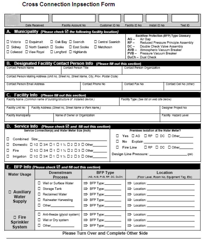
84
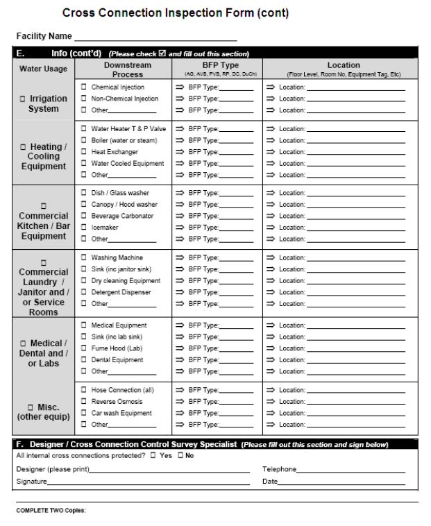
85