Matching gasification, conditioning and synthesis for the design of thermochemical biorefineries
|
|
|
- Rose Rice
- 5 years ago
- Views:
Transcription


1 Matching gasification, conditioning and synthesis for the design of thermochemical biorefineries Pedro Haro Fulbright-Schuman Scholar at Princeton University Asst. Professor at Universidad de Sevilla, Spain

2


3


4 University of Seville Matching gasification, conditioning and synthesis for TB Founded in 1505 One of the oldest Universities in Spain * with University of Málaga 4
 Transportation (biofuels): 4.3 % of total consumption 5")
5 Renewable electricity in Spain >40% renewable generation Rather stable increase of renewables Biomass and Waste are less than 3% of total generation (included in cogeneration) Transportation (biofuels): 4.3 % of total consumption 5
6 Bioenergy Group University of Seville Led by Prof. Pedro Ollero (2007-) Background in Coal conversion (power plants) Desulphuration (power plants) Several European Projects (Energy) Strong cooperation with the industry Energy: Total Gas & Power, CEPSA, Endesa Biofuels: Abengoa Waste management (waste-to-energy) Concentrated Solar Power (CSP) Plants Experimental, modeling and simulation Gasification pilot plant, modeling in CFD Temperature measurements using high-speed cameras for coal fluidized bed combustor/gasifiers Biofuel labs (catalysts tests), process design and simulation (Aspen) LCA: Dynamic modeling of climate impact (waste-to-energy and GHG removal technologies) 6
7 2.E-16 0.E+00 BAU Spain E-16 K kg -1-4.E-16-6.E-16-8.E-16-1.E-15 50% carbon captured in Bio-CCS net cooling Base case Sensitivity to renewable-derived plastic production Sensitivity to Bio-CCS incorporation
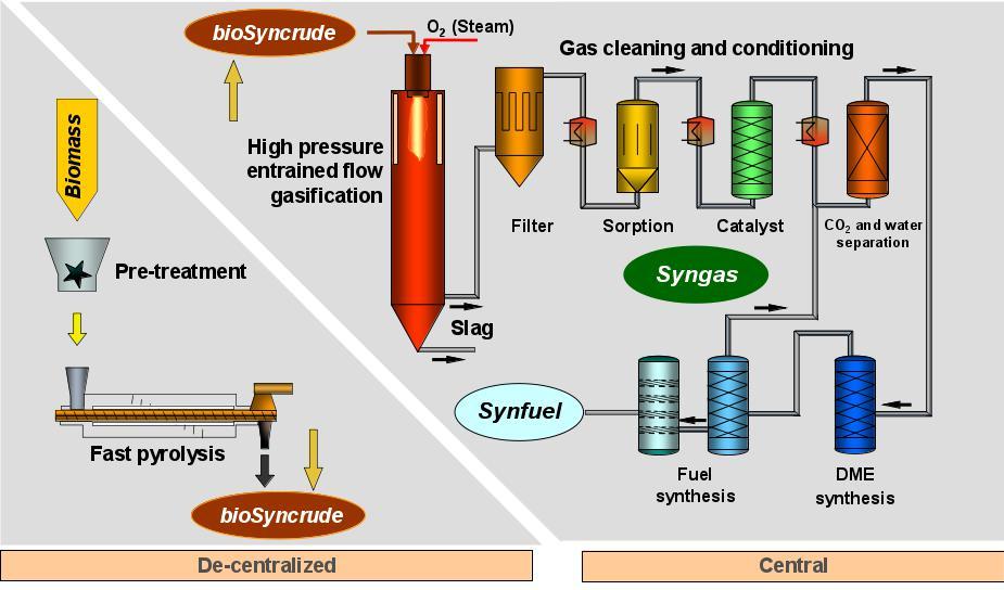
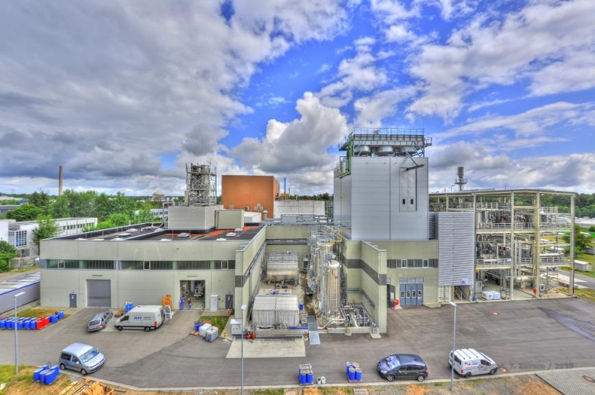
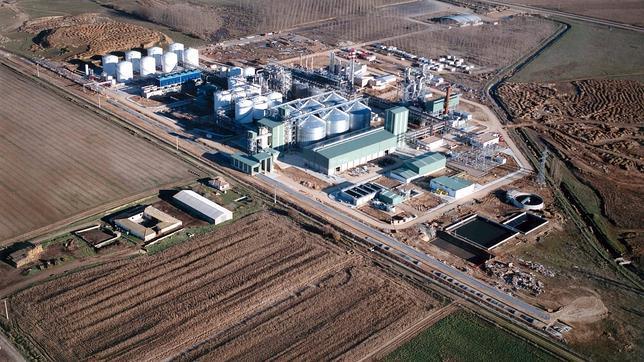
8 Personal experience in Thermochemical Biorefineries KIT: bioliq (Karlsruhe, Germany), 3 MWth Chalmers: GoBiGas (Gothenburg, Sweden), 20 MWth Bioenergy Group: Abengoa (Seville, Spain), conceptual design Common feedback for all cases: Complex designs High uncertainty Main objective: maximum production (despite complexity) Performance == Energy efficiency 8


9
10 Structure 1. Introduction to the problem 2. Proposal 10
 others (HTL, HTC, ) Syngas (gasification): mixture of H 2, CO, CO 2 and CH 4 conversion into multiple products Biofuels: methanol, ethanol, FT-liquids, dimethyl-ether (DME), hydrogen and")
11 Thermochemical Biorefineries Like conventional refineries, target is: large market and low-value products Thermal conversion: Gasification (entrained-flow, direct, or indirect gasification) Pyrolysis (fast) others (HTL, HTC, ) Syngas (gasification): mixture of H 2, CO, CO 2 and CH 4 conversion into multiple products Biofuels: methanol, ethanol, FT-liquids, dimethyl-ether (DME), hydrogen and substitute natural gas (SNG) the term BtL/G: biomass-toliquids/gases is also common 11
 Mixers/Splitters Distillation columns: zero flow, unrealistic temperatures, etc.")
12 Example of Thermochemical Biorefinery Energy integration Not very efficient removal Modular top-to-bottom design but for: Recycling of unconverted syngas Recycling of by-products Highly non-linear and non-convex behavior Kinetics: temperature, compositions (upgrading) Mixers/Splitters Distillation columns: zero flow, unrealistic temperatures, etc. issues Haro P, Villanueva Perales AL, Arjona R, Ollero P. Thermochemical biorefineries with multiproduction using a platform chemical. Biofuels, Bioproducts and Biorefining Mar 1;8(2):

13 Measuring the performance (efficiency) Different alternatives to measure performance: System expansion? Energy/Carbon basis? Haro P, Villanueva Perales AL, Arjona R, Ollero P. Thermochemical biorefineries with multiproduction using a platform chemical. Biofuels, Bioproducts and Biorefining Mar 1;8(2):
14 Strategies for an enhanced performance Optimization of gasification conditions (although not very realistic) Advanced syngas cleaning (high uncertainty) Complex synthesis loops (complex chemical routes, in-series reactors) Economics: Multiproduction (high-value/low-volume & low-value/high-volume) Thermochemical Biorefinery using a platform chemical Thermochemical Biorefinery combining direct routes Route 1 Product 1 Route 1 (BTL/G) Product 1 Platform Syngas Route 2 Product 2 chemical Syngas Route 2 (BTL/G) Product 2 Route 3 Product 3 Route 3 (BTL/G) Product 3 Haro P, Villanueva Perales AL, Arjona R, Ollero P. Thermochemical biorefineries with multiproduction using a platform chemical. Biofuels, Bioproducts and Biorefining Mar 1;8(2):
15 Example of a complex design Looking for a better performance results into: Higher energy efficiency (e.g. there are no by-products) Higher risk (higher capital investment and tighter operation) Feedstock pretreatment Gasification Syngas clean-up and conditioning DME synthesis Product separation Power generation Methanol synthesis DME synthesis Methanol Fuel gas CO 2 Biomass Dryer & Milling icfbg Steam methane reformer DME conversion DME Product separation CO 2 removal Power Island Water DME Hydrocarbonylation Product separation Methyl acetate Electric power Ethanol Haro P, Villanueva Perales AL, Arjona R, Ollero P. Thermochemical biorefineries with multiproduction using a platform chemical. Biofuels, Bioproducts and Biorefining Mar 1;8(2):
16 Complex Chemical Routes (Synthesis) Complex reaction systems In-series and parallel reactors Homogeneous catalysts EtOH MeOH AcOH CO, H 2 (syngas) CO, H 2 (syngas) 2.1 Eq. (1) CO Eq. (4) CH 3 OH Eq. (8) CO, H 2 (syngas) 2.1 DME CH 3 COOH CH 3 OCH 3 (DME) (acetic acid) CO CH 3 COOH Eq. (1) Eq. (8) Eq. (10) H 2 O CH 3 OH (acetic acid) Eq. (15) Eq. (10) H 2 O CH 3 COOCH 3 (methyl acetate) H 2 O CH 3 COOCH 3 CO (methyl acetate) CO Eq. (17) CH 3 OH EtOH (CH 3 CO) 2 O (acetic anhydride) FT, H 2, SNG H 2 Eq. (12) C 2 H 5 OH ButOH CO, H 2 (syngas) CO, H 2 (syngas) CO Eq. (1) Eq. (8) Eq. (11) H 2 CO CH 3 OH CH 3 COOH Eq. (1) Eq. (8) (acetic acid) Eq. (9) CH 3 OH CH 3 COOH (acetic acid) H 2 O CH CO, H 2 3 COOCH 2 CH 3 H 2 O (ethyl acetate) C 2 H 5 OH (syngas) C 2 H 5 OH Gasoline Eq. (1) Eq. (10) H 2 CH 3 OH Eq. (13) C 2 H 5 OH HMethyl 2 O CO Acetate CH 3 COOCH H 3 2 O (methyl acetate) Ac 2 O Eq. (17) CH 3 OH COOH (acetic acid) Olefins Eq. (1) Eq. (4) CH (CH 3 OCH 3 CO) 2 3 O (DME) (acetic anhydride) Eq. (18) H 2 Ethyl Acetate Eq. (15) C 2 H 5 OH CH 3 COOCH 3 (methyl acetate) CH 3 COOCH 2 CH 3 (ethyl acetate) Eq. (13) Eq. (12) H 2 CO, H 2 (syngas) C 2 H 5 OH Diesel Jet Fuel C 2 H 5 OH Chemicals Haro P, Ollero P, Villanueva Perales ÁL, Vidal Barrero F. Potential routes for thermochemical biorefineries. Biofuels, Bioproducts and Biorefining Sep 1;7(5):
17 Motivation for a deeper analysis Thermochemical biorefineries are not commercial The closest to be commercial experiences proved that complex designs are to be avoided Despite very complex designs, more complicate than for conventional processes, are not giving very promising results Current research efforts moving to: Power-to-gas Multiproduction/Polygeneration Multi-feedstock Solar gasification, microwave, ultrasound, etc. Therefore, there is a gap between research and industrial needs 17
18 General overview of the problem For a conventional gasification-based thermochemical biorefinery: Pyrolysis EF Cleaning (H 2 S) Torrefaction Biomass Dryer & Milling d-fb Tar cracker & Reforming Cleaning (H 2 S) WGS (optional) CO 2 removal (optional) Synthesis section Important impact i-fb Cleaning (tar, H 2 S) Reforming H 2 /CO, CH 4, CO 2, Uncertain impact [oil scrubber] Pressure No impact Surprisingly, there is a lot of uncertainty on the impact of gasification technologies on the synthesis Haro P, Gomez-Barea A. Unpublished results. 18
19 Synthesis Closer look at conventional biofuels Candidates for optimization Requirements for syngas composition (very) Hard to include in optimization (?) BtL/G process Methanol synthesis & MTG DME synthesis FT synthesis H 2/CO Observations % ratio a Hydrocarbons (molar) % CO 2 (molar) Pressure for synthesis (bar) 2 S = 2 b < S = 2 b < H2/CO = <10 <25 c Catalysts active for WGS, S = 2 b <10 < SNG 3 S = 3.00 b (10)15-25% Hydrogen synthesis Ethanol synthesis (desired maximum CH4) (minimum) (maximum) - <4 <5 >50 2 S2Mo catalyst, H2/CO = ppm H2S 1 Rh catalyst, H2/CO = Fermentation, 1.3 ( ) <15 c <10 50 <10 <20 c atmospheric a Only as an indication often given in the literature, not as a design parameter (see observations). b The stoichiometric ratio (S) is defined as the HH 2 CCCC CCCC+CCCC 2 molar ratio at the inlet. c Higher values might be possible []. Haro P, Gomez-Barea A. Unpublished results. 19
20 Synthesis: understanding some nuances Let s check a selection of conventional biofuels Only biofuels where recycling is possible CH 4 is an inert compound (build-up) 3 alternatives: Conventional process 10% v/v Electricity Reforming (SR, ATR, POx) CO2 removal (amines) H 2 /CO = 1.25 H 2 /CO = 1.70 Hydroc. = 3% CO 2 = 3% Reactor (50 bar) -30 C Upgrading Once-through Electricity Example (Dimethyl Ether) Reforming (SR, ATR, POx) CO2 removal (amines) H 2 /CO = 1.25 H 2 /CO = 1.25 Hydroc. = 5.6% CO 2 = 21.5% Reactor (50 bar) -30 C Upgrading Hybrid case 25% v/v Electricity Reforming (SR, ATR, POx) CO2 removal (amines) H 2 /CO = 1.25 H 2 /CO = 1.15 Hydroc. = 5.6% CO 2 = 21.5% Reactor (50 bar) -30 C Upgrading 20
21 Synthesis Loop: biofuel candidates Solution for the conventional case (maximum biofuel production) EtOH Methanol DME FT synthesis synthesis (S (Rh) 2 Mo) the difference are other hydrocarbons H 2 to upgrading area 15% 10% % 10% 15% v/v v/v v/v v/v (2) (2) (2) H 2 /CO H C 2 H 2 /CO 2 /CO = 1.1 = 2.3 = 22.1 (1) H (1) (1) 2 /CO H 2 2 H/CO 2 /CO = 1 = = 2 Reactor LT Reactor Upgrading 35 C Upgrading CH CH % (50 35 C (Moderate) CH CH 4 4% 4 4 3,.5% 4 2% 3% (3) ( C (50 20% (3) (3) S = 2 (35(50 bar) (Hard) bar) bar) (Easy) (Hard) (Hard) CO CO CO 2 4% 2 = 2 5% 3% 5% 50 ppm H 2 S (*) (*) (*) 4H 4H 2 2 4H + 2CO + 2 2CO + 2CO C CH 2 H 5 2 C OH + 2 H + 2H 5 OH H 2 O 2 + O H 2 O X = 22% 85-40% X = 20% (*) (*) 2H 3H 3CO CH 3 OCH 3 50% 2 + CO CH 3 OH 25% S = H 2 CO Q 2 (2) Q (**) Only (**) if H 2 Fe-based + H 2CO catalysts: (2) CO+CO 2 + 2CO CH 3 OH CH 3 OH X = 5% (2) X = 10% = (**) 3H CO CH OH 8% = 2 Q (**) 3H CO 2 CH 3 OH + H 2 O X = 8% (1) Q (1) (1) (***) (**) 2H 2 + CO CO 2 + H 2 O (***) H 2 + 3H CO CO CO +H CH 2 O 4 + H 2 O Equilibrium X = 2,5% Stream Stream1 (% (% 1 (% v/v) v/v) v/v) H 2 2 H CO CO CO CO CO CO CH CH CH Stream Stream3 (% 3 3 (% (% v/v) v/v) v/v) H 2 2 H CO CO CO CO CO CO CH CH CH the difference the difference the difference are DME are other are and other other hydrocarbons hydrocarbons hydrocarbons 21
22 Analysis of the Performance Global Conversion (%) Ethanol H 2 /CO=2 ratio Not feasible region DME H 2 /CO=1 ratio Methanol FT Conventional BtL/G studies Methanol DME / FT Ethanol H 2 /CO=2 ratio FT DME H 2 /CO=1 ratio Methanol Once-through (synthesis section) FT DME Ethanol Methanol 20 Hybrid Hydrocarbons in % molar (inlet synthesis loop) We need to understand the impact of recycling, not only a result from simulations Haro P, Gomez-Barea A. Unpublished results. 22
23 Matching: Conditioning CLEANED SYNGAS H 2/CO Hydrocarbons CO 2 Decision tree (biofuels) Hydrocarbons <10%? NO YES Hydrocarbons <10%? NO YES CLEANED SYNGAS pressure OK? H 2 /CO 2 or S admissible? H 2 /CO Hydrocarbons CO 2 NO NO YES YES YES Reforming (SR, ATR, POx) considering H 2/CO ratio H 2/CO or S admissible? NO WGS YES NO Hydroc. < 3% / Limited prod.? YES NO Oncethrough? YES Reforming (SR, ATR, POx) considering H 2 /CO ratio NO NO Multi-stage Hydroc. < 3% / compression CO 2 removal Limited prod.? (Amines, WGS Selexol, Rectisol) Oncethrough? CO 2 admissible? NO YES YES YES CO 2 removal (Amines, Selexol, Rectisol) SYNTHESIS SECTION pressure YES OK? NO Multi-stage compression SYNTHESIS SECTION Haro P, Gomez-Barea A. Unpublished results. 23
24 Matching: gasification-cleaning, conditioning & synthesis FB (oil (tar scrubber) EF cracker) CLEANED SYNGAS Scenario 1 Scenario 2 Reforming (SR, ATR, POx) WGS reactor CO 2 removal CO 22 removal SNG Ethanol Methanol FT-liquids DME SNG Ethanol (S 2 Mo) SNG Methanol SNG Ethanol Limited FT-liquids production Methanol Ethanol DME (S 2 Mo) FT-liquids Hydrogen Methanol DME DME Hydrogen Hydrogen H 22 /CO = Hydroc. = = 5-12% 1-2% <1% CO CO 22 = 20-30% 5-25% 10-20% Scenario 3 CO 22 removal Ethanol (S Limited production 2 Mo) FT-liquids DME* Ethanol DME (Rh) FT-liquids DME* Scenario 4 (no biofuel can be produced) Limited Limited production production DME* DME* Gasifier and cleaning become more important Haro P, Gomez-Barea A. Unpublished results. 24
25 Testing the matching Matching gasification, conditioning and synthesis for TB Only feasible cases Brute force 25
26 Parameters Results: Example (DME) Conventional synthesis (max. production) For a d-fb gasfier Matching gasification, conditioning and synthesis for TB Hybrid Once-through (Limited production) H 2 /CO (molar) CH 4 (% v/v) CO 2 (% v/v) DME (production) 9.18 MJ/kg dafb 3.84 MJ/kg dafb 6.57 MJ/kg dafb Methanol (production) Electricity (production) 0.69 MJ/kg dafb 0.75 MJ/kg dafb 1.18 MJ/kg dafb MJ/kg dafb 2.95 MJ/kg dafb 1.28 MJ/kg dafb Efficiency (LHV%) 43.0% 36.1% 43.3% Advantages 1. Higher global conversion to DME 2. Conversion of hydrocarbons into DME 1. No syngas conditioning a. Lower capital investment b. Reduction on operating cost (steam) 2. Larger combined cycle (larger efficiency) 1. No syngas conditioning 2. Larger syngas conversion than oncethrough 3. No CO 2 build-up (CO 2 is removed from the unconverted syngas due to cryogenic separation) Disadvantages 1. Reformer and CO 2 removal are necessary (capital- and energy-intensive section) 2. The reforming increases the H 2 /CO ratio above requirements 3. Low efficiency for electricity production 1. Low global conversion (only per-pass conversion) 2. Electricity has a lower price than DME 3. Higher methanol production due to the presence of CO 2 1. Electricity has a lower price than DME 2. Higher methanol production due to the presence of CO 2 3. Low efficiency for electricity production 26
27 Final remarks Lessons to be learn Natural limits to the process (seek the feasible combinations) Check alternatives for product maximization Further efforts should be made for the design of simple but profitable biorefineries designs Industry participation/leadership? Next: Evaluation/Optimization of first-ok-a-kind (FOAK) thermochemical biorefineries Uncertainty analysis (specific for FOAKs) 27


28 Thank you for your attention! Acknowledgements Fulbright-Schumann Program Universidad de Sevilla, VI Plan Propio de Investigación