A, B, C, D VENTILATION SYSTEMS: COMPARISON
|
|
|
- Allison Allen
- 5 years ago
- Views:
Transcription

1 A, B, C, D VENTILATION SYSTEMS: COMPARISON ATIC-ULg Ventilation day 19/11/2015 Samuel Gendebien University of Liège
2 Table of content Objectives of the presentation Introduction - Key figures Definitions Classification of ventilation systems Simulation Conclusions 2
3 Table of content Objectives of the presentation Introduction - Key figures Definitions Classification of ventilation systems Simulation Conclusions 3
4 Objectives of the presentation Brief overview of ventilation systems Definition, classification, advantages and drawbacks Introduction of some innovative technologies presented today Framework of the day Conclusion related to the use of ventilation systems Presentation of some simulation results 4
5 Table of content Objectives of the presentation Introduction - Key figures Definitions Classification of ventilation systems Simulation Conclusions 5
 Retrofit rates: 1% per year in most of the EU countries, 0.")
6 Key figures *Belgium 37% Final energy consumption by sector in 2011 (Europe of 27) *Labothap (2015) Retrofit rates: 1% per year in most of the EU countries, 0.8% in Belgium, 6
.")
7 Introduction First retrofit options to be considered for existing residential buildings are the improvement of the thermal insulation and air tightness. This represents a high potential of energy savings but also a potential reduction of Indoor Air Quality (IAQ). Improving the building envelope tends to increase the relative part of the energy consumption due to ventilation. Many studies estimates the total energy losses due to ventilation between 20% and 50% (in building with a high thermal insulation). 7

8 Key figures 8
9 Key figures Annual sales Mechanical HR units Total number EU27 Medium climate Cold climate Warm climate Past annual sales Forecast Year EU27 Forecast and Market trends (Ecolot design (2012)) 9
10 Key figures Seppanen (2012) showed an important changement in the ventilation market in Belgium: - Before 2007, only 0.68% of buildings are equipped with mechanical ventilation systems; - 5% of buildings constructed during years 2007 and 2008 are equipped with mechanical ventilation systems; - 40% of buildings constructed after 2008 are equipped with mechanical ventilation systems. 10
11 Table of content Objectives of the presentation Introduction - Key figures Definitions: just a short recall... Classification of ventilation systems Simulation Conclusions 11

12 Definitions Aeraulic has an influence on at least 4 fields of the building (Morel et Gnansounou, 2007): o o o o The Indoor Air Quality (IAQ) Occupants health Heat losses Energy consumption Internal and superficial condensation issues Building sustainability Thermal comfort o Building is a selective protection against outdoor conditions: the sun, the rain, the wind but indoor conditions are also polluted by: Human: CO 2, H 2 O, metabolic heat, bioorganic et inorganic effluents, bacteria, tobacco smoke Human activity (kitchen, bathrooms, ) Need of air renewal 12
13 Definitions Air exchange of outdoor air with air already in a building can be divided into two broad classifications: ventilation and in/ex-filtration. - Ventilation is intentional introduction of air from the outside into a building; it is further subdivided into natural and mechanical ventilation: Mechanical (or forced) ventilation is the intentional movement of air into and out of a building using fans and intake and exhaust vents. Natural ventilation is the flow of air through open windows, doors, grilles, and other planned building envelope penetrations, and it is driven by natural and/or artificially produced pressure differentials. - Infiltration is the flow of outdoor air into a building through cracks and other unintentional openings and through the normal use of exterior doors for entrance and egress. Infiltration is also known as air leakage into a building. Exfiltration is leakage of indoor air out of a building through similar types of openings. Like natural ventilation, infiltration and exfiltration are driven by natural and/or artificial pressure differences. 13
14 Table of content Objectives of the presentation Some key figures Definitions Classification of ventilation systems Simulation Conclusions 14


15 Classification of ventilation systems System A System B Natural ventilation System C Mechanically supplied ventilation System D Mechanical extracting ventilation Mechanically supplied and extracting ventilation 15
16 C O N C E P T I O N Criteria System A System B System C System D Renovation case Envelope air tightness Complexity Ducting Simple to install Need a good envelope air tightness Need controlled supply orifice and vertical extracting duct Need space for air extracting duct No always suitable for renovation Need a really good envelope air tightness Can be installed in new and retrofitted buildings Need a really good envelope air tightness No suitable for renovation Need a perfect envelope air tightness Quite simple Quite simple System more complex Need space for vertical air extracting duct and for supply ducts Need a set of air extracting ducts Need set of air extracting and supplying ducts I A Q Air filtration No air treatment allowed Supply air can be filtered Gaz leaks (ground) Risk if the building is depressurized Over pressurization of the building reduces risks Supply air can not be filtered Depressurization can allow for gaz draught from the ground Air can be filtered and treated (T, RH) No risks because some rooms can be overpressurized N O I S E Sound transmission Sound generation Controlled supply orifice allows for noise transmission from outdoor No sound generation Good sound attenuation except if the air supplying duct are not well installed Sound generation due to air supplying fans Controlled supply orifice allows for noise transmission from outdoor Sound generation due to air extracting fans Sound transmission is limited if well designed Sound generation due to air extracting and air supplying fans
17 C O N T R O L E N R G Y C O S T Criteria System A System B System C System D Supplied air flow rate Extracted air flow rate Flow rates management Maintenance Recovered heat Electrical consumption Dependent on the natural phenomena and the wind Dependent on the natural phenomena and the wind Control supplied orifice but flow rates are never perfectly known Little maintenance for the components of the system Supplied air flow rates are controlled No control on the extracted air flow rates per room Only the supplied air flow rate is really controlled Regular maintenance No control on the supplied air flow rates per room Extracted flow rates are controlled Only the extracted air flow rate is really controlled Regular maintenance No recovered heat No recovered heat Active heat recovery No electrical consumption Electrical consumption Electrical consumption Global cost Installation quite simple Quite expensive Exploitation cost OK Supplied air flow rates are controlled Extracted air flow rates are controlled System really suitable for controlled flow rates and an automatic regulation Regular maintenance (inspection and cleaning) Passive and active heat recovery Electrical consumption System expensive, especially if no recovered heat
18 Ventilation systems System A System B System C* System D* Coupled with PCM for TES application * DCV HR No HR HR No HR Run-around Passive heat recovery Fixed plates Rotary wheel Active heat recovery Heat pump Heat pipe Total HR (sensible & latent) Sensible Metal types Polymer Centralized Room based Integrated into windows Wall mounted
19 Table of content Objectives of the presentation Some key figures Definitions Classification of ventilation systems Simulation Conclusions 19
20 Annual performances: numerical simulation Global thermo-aeraulic building model* Thermal behavior Airflow building network *Model developed by Ulg in Modelica language Available in open-access 20

21 Annual performances: numerical simulation Investigated apartment Floor Area: 121 m² External Walls U-value: parameter Windows U-value: parameter Infiltration Rate (50 Pa): parameter Nominal Ventilation Rate: 286 m³/h Occupancy profile: 4 people from 4PM to 8AM DHW tank Volume: 200 l Set-Point Temperature for DHW: 55 C Inside Set-Point Temperature: 18 & 21 C
22 Annual performances: numerical simulation 3 constructive characteristics Old building U 1.6 U 5 Ach 6 Massive structure (Brick wall) Retroffited building U 0.46 U 3.5 Ach 2.4 Massive structure (Brick wall + external insulation) New building U 0.24 U 1.8 Ach 1 Massive structure (Brick wall + external insulation)
23 Annual performances: numerical simulation Bruxelles (Belgium) Bordeaux (France) Ostersund (Sweden)
24 Influence of the ventilation system on the indoor CO2 concentration * Same conclusion can be drawn for other climate


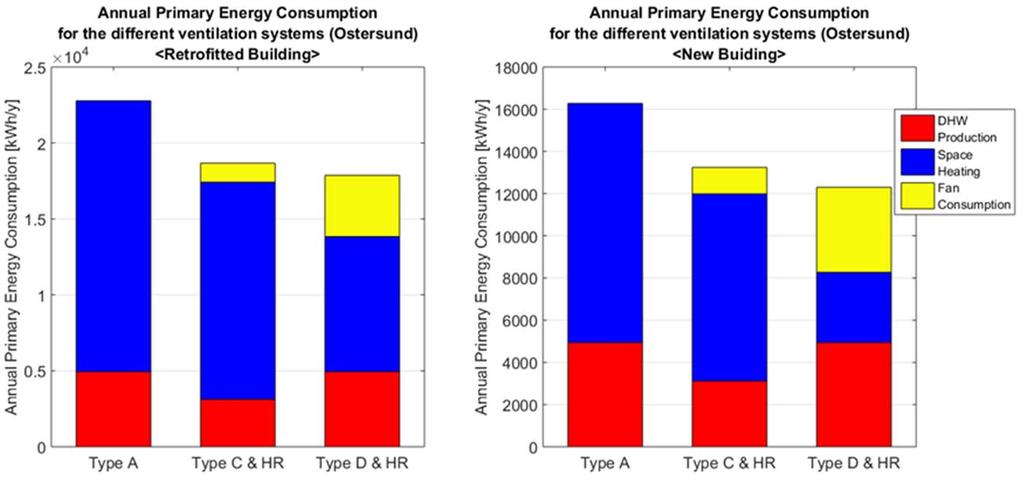
 No point of using System D with HR in warmer climate Heat recovered over")
25 Ventilation system vs climate? Systems C and D consume more than system A for each considered climate (price for a better control of flow rate): Fan consumption and no HR System D with HR seems more suitable for cold climate Heat recovered over one year > Fan consumption (! ε, ΔP, η!) No point of using System D with HR in warmer climate Heat recovered over one year < Fan consumption (! ε, ΔP, η!) Fan consumption is not negligible (! ΔP and η!)

26 Active heat recovery? Decrease of the energy demand due to better airtightness and insulation Rise of the relative part due to the DHW production Same conclusions for other climate

27 Active heat recovery?
28 Table of content Objectives of the presentation Some key figures Definitions Classification of ventilation systems Simulation Conclusions 28
29 Conclusions Relative part dedicated to ventilation and domestic hot water consumption will increase in the future Need for innovative ventilation systems Large amount of selection criteria for ventilation systems comparison Advantages and drawbacks for each ventilation system (A, B, C, D) Quite difficult to draw general conclusions concerning the use of a specific ventilation system: dependent on several parameters (airthightness, climate, construction or retroffiting, investment cost, space dedicated to ductings, noise,...) Importance of the fan consumption/performance Ventilation systems should be selected on a case-by-case basis depending on the parameters and the situation of the building 29
30 Thank you for your attention! 30