3. Compressor. Gas Turbines for Power Plants 3. Compressor 1 / 136
|
|
|
- Joella Sharlene Dalton
- 5 years ago
- Views:
Transcription


1 3. Compressor Gas Turbines for Power Plants 3. Compressor 1 / 136
2 Contents Basic Principles of an Axial Compressor Compressor Thermodynamics and Fluid Dynamics 18 Dimensionless Numbers 48 Basic Sizing Parameters 56 Compressor Blade Shapes 65 Degree of Reaction 73 Compressor Losses 80 Stall and Surge 89 Centrifugal Compressor 1 Developmental Trends 18 Gas Turbines for Power Plants 3. Compressor / 136
3 Configuration of a Gas Turbine A compressor is a device that pressurizes a working fluid 7FA, GE VIGV Air Extraction Ports Transition Piece Diffuser Starter & Gear Box Air Inlet Compressor Combustor Turbine Exhaust Cold Section Hot Section Gas Turbines for Power Plants 3. Compressor 3 / 136
4 Basic Requirements of Compressor The basic function of a compressor is to utilize shaft work to increase the stagnation pressure of the air before it is expanded through the turbine. The basic requirements of compressors for power generation gas turbine application are high efficiency, high air flow capacity per unit frontal area, and high pressure ratio per stage. Compressors consume about 50% of mechanical energy produced by turbine. Therefore, compressor efficiency is essential factor to overcome high energy price. The larger the gas turbine, the higher the efficiency of gas turbine, and the lower gas turbine price per unit power output. The higher pressure ratio per stage, the shorter the compressor length. In addition, the mechanical design should be simple, so as to reduce manufacturing time and cost. The resulting structure should be mechanically rugged and reliable. Gas Turbines for Power Plants 3. Compressor 4 / 136
5 Gas Turbine Matching Gas Turbine Output (MW) Air Flow Rate (lbs/s) Compressor Power (MW) Total Turbine Output (MW) W C /W T Typhoon Centaur Mars MS5371PA RB MS6581B Trent GT 8C MS6101FA MS711EA E MS741FA MS9351FA Mean 0.55 In a gas turbine, approximately 50 percent of the total work produced in the turbine is consumed by axial compressor. Consequently, maintaining a high compressor efficiency is very important. Gas Turbines for Power Plants 3. Compressor 5 / 136
6 Introduction to Compressor If pressure rise is small and mass flow is large, the device is a called a fan, whereas if the pressure rise is high, the device is called a compressor. Sometimes a middle-range pressure rise device is termed a blower. The compressors in most gas turbine applications, especially units over 5 MW, use axial flow compressors. The axial compressor is the most complicated component to design in an aerodynamic point of view. An axial flow compressor is one which the flow enters the compressor in an axial direction (parallel with the axis of rotation), and exits from the gas turbine also in an axial direction. The axial-flow compressor compresses its working fluid by first accelerating the fluid and then diffusing it to obtain a pressure increase. The axial flow compressor consumes around 50% of the power produced by the turbine section of the gas turbine. The increase in gas turbine efficiency is dependent on four basic parameters: pressure ratio, TIT, compressor efficiency, and turbine efficiency. In an axial flow compressor, air passes from one stage to the next, each stage raising the pressure slightly. However, by producing low-pressure increases on the order of 1.1 : 1 to 1.4 : 1, very high compressor efficiency can be obtained. The use of multiple stages permits overall pressure increases up to 40:1. The industrial gas turbine has been conservative in the pressure ratio and TIT. This is because the industrial gas turbines given up high performance for both rugged operation and long life. However, this has all changed in the last 10 years. The performance of the industrial gas turbines improved dramatically to overcome the increased energy cost. In addition, the performance gap between aerospace engines and industrial ones reduced dramatically. Gas Turbines for Power Plants 3. Compressor 6 / 136

7 Types of Compressor Type Pressure Ratio per Stage Industrial Aviation Research Efficiency (%) Operational Range (Surge to choke) Centrifugal Large, 5% Axial Narrow, 3-10% Hub Shroud Outflow Inflow Axis of Rotation Stage A Centrifugal Compressor An Axial Flow Compressor Gas Turbines for Power Plants 3. Compressor 7 / 136
8 Pressure ratio Pressure Ratio [1/4] Compressor pressure ratio of a gas turbine engine is an extremely important design parameter. Pressure ratio = total pressure at compressor outlet total pressure at compressor inlet In general, the higher the pressure ratio, the greater thermal efficiency. The growth of both the pressure ratio and TIT parallel each other, as both growths are necessary to achieving the increase in thermal efficiency in gas turbines The expression compression ratio is not used for gas turbines because this is a ratio of air density rather than air pressure by definition. Aircraft Industrial Currently, some engines have compressor pressure ratio of 3:1 (40:1 for aircraft gas turbines) Year Gas Turbines for Power Plants 3. Compressor 8 / 136
9 Pressure Ratio [/4] A typical axial flow compressor consists of a series of stages; each stage has a row of rotor blades followed by a row of stator blades which is stationary. The length of the blades and the annulus area, which is the area between the blade root and tip, decreases throughout the length of the compressor. This reduction in flow area compensates for the increase in fluid density as it is compressed, permitting a constant axial velocity. In the heavy duty gas turbines, pressure ratio per stage is reduced to provide stable operation. For example, GE s H-class gas turbine with 18 stages of compressor has a pressure ratio per stage of In the multistage compressor, the pressure ratio is obtained by multiplying the all pressure ratio per stage. (GE HA gas turbine with 14 stages at 1.45 per stage gives a factor of ). Gas Turbines for Power Plants 3. Compressor 9 / 136
10 Pressure Ratio [3/4] Simple Cycle Analysis [1/] p q in 3 T (h) 3 q in w in w out w out 4 w in 1 q out 4 1 q out s q h h1 1 1 w Process Component Heat Work Process 1 Compressor q 1 = q C = 0 w 1 = w C = (h h 1 ) Power in (adiabatic compression) 3 Combustor q 3 = q B = h 3 h w 3 = w B = 0 Heat addition at constant pressure 34 Turbine q 34 = q T = 0 w 34 = w T = h 3 h 4 Power out (adiabatic expansion) 41 Exhaust q 41 = q E = (h 4 h 1 ) w 41 = w E = 0 Heat release at constant pressure Gas Turbines for Power Plants 3. Compressor 10 / 136
11 Thermal Efficiency Pressure Ratio [4/4] Simple Cycle Analysis [/] th net work ouput heat input w q sys in w w q h h h h q q q 3 h h 3 T T T T 3 T T 1 th 1 1 r 1 / 1 c r p p 1 p p 3 4 c r 1 Thermal efficiency in a simple cycle gas turbine increases with pressure ratio and specific heat ratio. The increasing rate of the thermal efficiency is getting smaller as the pressure ratio increases Pressure Ratio [r] Gas Turbines for Power Plants 3. Compressor 11 / 136


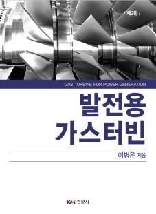
12 Configuration of a Typical Axial Compressor 7EA, GE Gas Turbines for Power Plants 3. Compressor 1 / 136
![Variable Inlet Guide Vanes [1/] Task 1: When designing a compressor with the reaction blades, the first stage must be preceded by pitch variable blades, known as variable inlet guide vanes, to](/docs-images/93/111989371/images/13-0.jpg "provide pre-swirl and the correct velocity entrance angle to the first stage rotor.")

13 Variable Inlet Guide Vanes [1/] Task 1: When designing a compressor with the reaction blades, the first stage must be preceded by pitch variable blades, known as variable inlet guide vanes, to provide pre-swirl and the correct velocity entrance angle to the first stage rotor. This means that VIGVs serve to direct the axially approaching flow correctly into the first row of rotor blades because those are very sensitive to any small change in incidence in flow angle or non-uniformity in velocity. Task : Additionally, its position affects the quantity of compressor inlet air flow. Therefore, VIGVs are one of the useful tools to control stall occurred in compressors. Task 3: IGVs also serve the purpose of preventing the injection of foreign objects into the engine. Similar vanes, often known as the EGVs (Exit Guide Vanes) are placed at the compressor exit to remove the rotational moment imparted to the air during compression. Engine Center Line VIGV 1 st Stage Compressor Blade Gas Turbines for Power Plants 3. Compressor 13 / 136
![Variable Inlet Guide Vanes [/] The gas turbine output is controlled by a combination of VIGV control, and TIT control.](/docs-images/93/111989371/images/14-0.jpg "The TIT is controlled by a combination of the fuel flow admitted to the combustor and the VIGV setting.")

14 Variable Inlet Guide Vanes [/] The gas turbine output is controlled by a combination of VIGV control, and TIT control. The TIT is controlled by a combination of the fuel flow admitted to the combustor and the VIGV setting. Modern gas turbines are allowing a high gas turbine exhaust gas temperature down to approximately 40% GT load. Below that level, the turbine inlet temperature is further reduced because the airflow cannot be further reduced. Gear Ring IGV Pinion Gear VIGV Gas Turbines for Power Plants 3. Compressor 14 / 136


15 Rotor and Stator [1/3] Gas Turbines for Power Plants 3. Compressor 15 / 136


16 Rotor and Stator [/3] Stator buildup Rotor buildup Compressor rotor stacking Gas Turbines for Power Plants 3. Compressor 16 / 136
17 Rotor and Stator [3/3] The axial compressor is a multi-stage unit as the amount of pressure rise by each stage is small; a stage consists of a row of rotor blades followed by a row of stator vanes. The entering air is accelerated in the rotor, that is, kinetic energy is transferred to the air, and then it is diffused in the stator to convert the kinetic energy into a pressure rise. The job of the rotors is to increase pressure using mechanical energy transmitted from turbine. Stage The stator vanes are placed to the rear of the rotor blades to receive the air at high velocity and act as a diffuser, converting kinetic energy to pressure energy. The stator also have a secondary function of directing airflow to the next stage of compression as the desired angle. From the front to rear of the compressor, i.e. from the low to high pressure end, there is a gradual reduction of annulus area between to rotor hub and the stator casing. This is necessary to maintain a near constant air axial velocity as the density increases through the length of the compressor. The convergence of the air annulus is achieved by the tapering of the casing or rotor. A combination of both is also possible, with the arrangement being influenced by manufacturing problems and other mechanical design factors. Gas Turbines for Power Plants 3. Compressor 17 / 136
18 Basic Principles of an Axial Compressor Compressor Thermodynamics and Fluid Dynamics Dimensionless Numbers Basic Sizing Parameters Compressor Blade Shapes Degree of Reaction Compressor Losses Stall and Surge Centrifugal Compressor Developmental Trends Gas Turbines for Power Plants 3. Compressor 18 / 136
19 Direction of Rotation Cascade The compressor is composed of several rows of airfoil cascades. That is, several blades placed in a row is called as cascade. The high pressure zone air of the first stage blade being pumped into the low pressure zone of its stator. The high pressure zone of the first stage stator vane then pumps into the low pressure zone of the second stage rotor blade. This cascade progress continues to the last stage of compression. It might appear that the rotor blade high and low pressure zone might cancel each other out as they blend together; but the overall effect of the divergent shape of the flow path results in a net decrease in velocity and an increase in static pressure. H L H L H L H L H L H L H L H L H L H L H L H L IGVs First Stage Rotor Blades High Pressure Stator Low Pressure Second Stage Rotor Blades Stator Blades Gas Turbines for Power Plants 3. Compressor 19 / 136
20 Compressor Cascade Nomenclature [1/3] C s c 1 a 1 Point of max. camber i c 1 1 = blade inlet angle = blade exit angle 1 = air inlet angle = air exit angle c 1 = air inlet velocity c = air exit velocity C = chord s = pitch (or space) = blade camber angle = 1 = deflection = 1 = stagger or setting angle i = incidence angle = 1 1 = deviation angle = = solidity (= C/s) AR = aspect ratio (= h/c) Gas Turbines for Power Plants 3. Compressor 0 / 136
21 Compressor Cascade Nomenclature [/3] Nomenclature Description Camber line A line drawn halfway between the two surfaces, pressure and suction Camber The distance between the camber line and the chord line Camber angle, The turning angle of the camber line (= 1 ) Blade shape Aspect ratio, AR Pitch, s (blade spacing) Solidity, The blade shape is described by specifying the ratio of the chord to the camber at some particular length on the chord line, measured from the leading edge Aspect ratio is the ratio of the blade length (height) to the chord length The term hub-to-tip ratio is used frequently instead of aspect ratio It is important when 3-D flow characteristics are discussed The pitch of a cascade is the distance between blades, usually measured between the camber lines at the leading edges or trailing edges of the blades The ratio of the chord length to the pitch is the solidity of the cascade ( = C/s) It measures the relative interference effects of one blade with another 0.5~0.7: isolated airfoil test data can be applied with considerable accuracy 0.7~1.0: isolated airfoil test data can be applied with reduced accuracy 1.0~1.5: cascade data are necessary (majority of present designs belong to) 1.5 : channel theory can be employed Blade inlet angle, The angle formed by a line drawn tangent to the forward end of the camber line and the axis of 1 the compressor Blade exit angle, The angle formed by a line drawn tangent to the rear of the camber line and the axis of the compressor Gas Turbines for Power Plants 3. Compressor 1 / 136
22 Compressor Cascade Nomenclature [3/3] Nomenclature Stagger angle (setting angle ), Description The angle formed by a chord line and the axis of the compressor It is also called as setting angle of the blade High aspect ratio blades often are pretwisted so that at full speed centrifugal forces acting on the blades will untwist the blades to the designed angle. The pretwist angle at the tip for blades with AR of about 4 is between ~4. Absolute air inlet angle, 1 Absolute air exit angle, Relative air inlet angle, 1 Relative air exit angle, Angle between absolute incoming velocity and axial direction. Angle between absolute leaving velocity and axial direction. Angle between relative incoming velocity and axial direction. (not shown in the figure) Angle between relative leaving velocity and axial direction. (not shown in the figure) Incidence angle, i The difference between the blade inlet angle and air inlet angle (i = 1 1 ) Angle of attack, The angle between the inlet air direction and the blade chord ( = 1 ) Deviation angle, As the air is turned by the blade, it offers resistance to turning and leaves the blade at an angle, greater than, so called air exit angle, The deviation angle is defined as the difference between the blade or the camber angle and the average flow angle ( = ) Deflection angle, The angle formed by air inlet angle and air exit angle ( = 1 ) Gas Turbines for Power Plants 3. Compressor / 136
23 Rotor Stator Velocity Triangles [1/4] 1 3 r Flow direction CL z Gas Turbines for Power Plants 3. Compressor 3 / 136
24 Velocity Triangles [/4] Most axial compressors are designed on the basis of constant axial velocity throughout the stages because of the simplifications of design procedure of the subsequent stage. c : absolute velocity w : relative velocity u : tangential velocity of blade IGV Fluid velocity is an important variable governing the flow and energy transfer within a compressor. The absolute velocity ( ) is the fluid velocity relative to some stationary point and is usually parallel to the stator (stationary blade). When considering the flow across a rotating element like a rotor, the relative velocity ( w ) is important and is usually parallel to the rotating element. Vectorially, the relative velocity is defined as: where u of the rotor. w c u c is the tangential velocity w 1 w c v z, c, u Rotor Stator 1 v z,1 u 1 Shaft CL 3 c 3 1 c 1 c,1 Gas Turbines for Power Plants 3. Compressor 4 / 136
25 The air approaches the rotor blades with an absolute velocity c 1 at an inlet angle 1 to the axial direction. In combination with the tangential velocity of the rotor blades u, its relative velocity will be w 1 at an inlet angle 1. (w 1 = c 1 u) The relative velocity w 1 should align closely with the rotor blade angle at the inlet. After passing through the diverging passages formed between two adjacent rotor blades which do work on the air and increase its absolute velocity (from c 1 to c ), the air will have relative velocity w at an exit angle which is less than 1. This turning of the air towards the axial direction is necessary to provide the increase of effective flow area. The rotor blade turns the relative velocity w 1 to w, thereby imparting angular momentum to the air and thus increasing the absolute tangential velocity. For a rotor, c c 1 and w w 1. This is because the kinetic energy is added by the shaft in the absolute frame, and rotor blade passage acts like a diffuser in relative frame. The fact of c c 1 can be explained by the fact that the mechanical energy transmitted from the turbine will be transferred to the air through the rotor and the absolute velocity of the air increases. The exit relative velocity w is nearly parallel to the blade at exit. The relative velocity w in combination with u gives the absolute velocity c at exit of the rotor at an angle. Velocity Triangles [3/4] The absolute velocity at rotor exit should line up with the stator blades. The air then pass through the passages formed by the stator blades wherein it is further diffused to velocity c 3 at an exit angle 3. In most designs, it is equal to 1 so that it is prepared for entry to the next stage. (c 3 =c 1, and 3 = 1 ) Gas Turbines for Power Plants 3. Compressor 5 / 136
26 Velocity Triangles [4/4] The basic principle of acceleration of the working fluid, followed by diffusion to convert acquired kinetic energy into a pressure rise, is applied in the axial compressor Air is turned through the proper angle by the VIGVs before it impinges on the rotor blade of the first stage. Work transmitted from the turbine is added to the air by the rotor blades, thereby increasing its stagnation enthalpy, pressure, temperature, and kinetic energy. The flow is discharged at a proper angle of attack to stator blades where the static pressure is further increased by flow diffusion. IGV Rotor 1 Stator 1 c 1 w 1 u c w u h o, p o, T o h, p, T c 3 w 3 u Rotor Shaft CL The stagnation pressure remains nearly the same through the stator (except for losses), but the static pressure is further increase while the kinetic energy decreases. The air is directed to the second stage rotor, and the process repeats itself. Gas Turbines for Power Plants 3. Compressor 6 / 136
27 Change of Stagnation Pressure In order to investigate the change of stagnation pressure during the air pass through the rotor passage, we can consider energy equation. In an open system, the first law of thermodynamics is as follows, p p p q 1 1 u u1 p p1 1 c c1 gz z1 w1 q 1 0 u z 1 c p u1 z p1 c o, o,1 w1 p o, o,1 w 1 (adiabatic process) The equation (1) can be reduced as follows, The sign of the (the change of the internal energy can be ignored) (the change of the potential energy can be ignored) 1 w 1 is negative because it is a supplied work to the compressor. Therefore, the following conclusion can be obtained. (1) In the stator passage, there is no work supplied and produced. Therefore, w 1 =0 Therefore, the following conclusion can be obtained. p p o, o,1 Gas Turbines for Power Plants 3. Compressor 7 / 136
28 Rotor Rotor Rotor IGV Stator Stator Stator Variation of Velocity and Pressure An axial flow compressor compresses its working fluid by first accelerating the fluid and then diffusing it to obtain a pressure increase. The fluid is accelerated by a row of rotor and diffused by a row of stator. The diffusion in the stator converts the velocity increase obtained in the rotor to a pressure increase. C L h o, p o, T o : total values h, p, T: static values Even though the pressure is rising dramatically, the velocity is held relatively constant. c: absolute velocity Compressor exiting velocity is lower than compressor entering velocity for flame stability in combustion chambers. ho 1 h c c p T o 1 c 1 c c T p To T c p It should be noted that total conditions for pressure, temperature, and enthalpy increase only in the rotor where energy is inputted to the system. It is common in an multistage axial flow compressor that the enthalpy rise per stage is constant, rather than that the pressure rise per stage is constant. Gas Turbines for Power Plants 3. Compressor 8 / 136
29 Flow through a Cascade w 1 u c 1 Axial Direction Axial Direction w c u Compressor Blades Blade Direction Blade Direction Turbine Blades w c u w 3 u c3 Compressor Turbine Compressor Turbine Blade flow path Diverge (diffuser) Converge (nozzle) Absolute velocity of flow Increase Decrease Relative velocity of flow Decrease Increase Pressure Rise Drop Work transfer Input (through rotor) Output (through bucket) Enthalpy (Temperature) Increase Decrease Airfoil shape Slender Thick (and composed of many circular arcs) Flow in a blade passage Decelerate (thick boundary layers) Accelerate (thin boundary layers) Possibility of flow separation Large Small Flow turning Small (typically 30 to avoid flow separation) Large (typically 100) Number of stages Large (because of small flow turning) Small (because of large flow turning) Blade height Decrease Increase Gas Turbines for Power Plants 3. Compressor 9 / 136
30 Compressor Work [1/3] Brayton Cycle Technical Work: w1 dp 1 p p p b 3 b 3 3 w in w out w sys a 1 4 a (a) (b) (c) Gas Turbines for Power Plants 3. Compressor 30 / 136
31 Compressor Work [/3] Air 1 Fuel Combustor 3 Exhaust gas 4 h 3 3 Compressor Turbine Power p T h c o o o p c = total pressure = total temperature = specific stagnation enthalpy = specific heat = specific heat ratio = isentropic efficiency of compressor wc ho, ho,1/ c cpt o, To,1/ c cpto c cpto c,1 T T r o, o,1 1, 1 cpto 1 c 1,1 p p p r p o, o,1 o, o,1 1 T T 1 o, o,1 1 s 1) 압축기로유입되는공기의온도가증가할수록압축기에서소모하는일의크기가증가 가스터빈출력저하 ) 각단에서동일한압력비를얻기위해서는압축기앞부분단보다뒷부분단에서더큰일이필요 축류압축기뒷부분단이앞부분단에비해효율이낮음 압력비가증가할수록압축기효율이낮아짐 Gas Turbines for Power Plants 3. Compressor 31 / 136
32 Rotor Stator Ideal compressor work Practical compressor work Compressor Work [3/3] Compression Line The rotor compresses the air from p 1 (or p o,1 ) to p (or p o, ). The purpose of the stator is to convert kinetic energy from c / to c 3 / and to further increase the static pressure. T (h) o,3ss o, o,3 p o, p o,3 p 3 The static pressure increases from p to p 3 along the line - 3, and the stagnation pressure decreases from p o, to p o,3 due to viscous losses. A large increase in velocity at the exit of the stage is thus avoided. In the compression process certain losses are incurred that result in an increase in the entropy of the air. Thus, in passing through a compressor, the velocity, the pressure, the temperature, the density, the entropy of the air are changed. 1/ c o,3s 3ss s 1/ c 1 o,1 1 3s 3 p p o,1 p 1 1/ c 3 s [ Compression line ] Gas Turbines for Power Plants 3. Compressor 3 / 136
33 Compressor Efficiency [1/4] Isentropic Efficiency c w w c, ideal c, actual h o,3s h o,3 h h o,1 o,1 h o,s h o, h h o,1 o,1 c = Work input to an isentropic compressor Work input to an actual compressor A constant pressure line has a varying slope proportional to the temperature. This fact can be demonstrated by Gibbs equation, Tds dh dp T s T p c p This equation shows that the slope of a constant pressure line increases with temperature. T (h) p = const. ds dt s Additionally, the equation gives the fact that the vertical distance between two different constant pressure lines increases with temperature. This means that two different constant pressure lines diverge as the entropy increases. In the axial compressor, the work input needed for a given pressure rise is greater for the rear stages than front ones. This is because temperature is higher at the rear stages, and thus the work input required by the rear stages is increased. This is the reason why the isentropic efficiency becomes lower as the overall pressure ratio increases. Gas Turbines for Power Plants 3. Compressor 33 / 136
34 Polytropic Efficiency [1/] Polytropic efficiency is another concept of efficiency often used in compressor evaluation. It is the true aerodynamic efficiency exclusive of the pressure ratio effect. It is defined as the isentropic efficiency of an infinitesimally small step in the compression process(walsh and Fletcher, 1998). Therefore, it is often referred as small stage or infinitesimal stage efficiency. It is defined by dh s p dh Compressor Efficiency [/4] From Gibbs equation and the definition of specific heat at constant pressure Tds dhs dp 0 dh c p dt Therefore, dp 1 dp / p p c dt dt / T p T (h) T os +dt os dh s T o +dt o p o +dp o p o Integrating between 1 and (initial and final state), it can be obtained T o p 1 po, ln po,1 T o, ln To,1 [ Infinitesimal compression process ] s Gas Turbines for Power Plants 3. Compressor 34 / 136
35 Polytropic Efficiency [/] Compressor Efficiency [3/4] Polytropic efficiency is not used directly in design point calculation. However, it is important for comparison of the compressors having different pressure ratio. Although exactly same technologies and frontal area are used in the design of two compressors having different pressure ratio, the isentropic efficiency of the compressor having low pressure ratio is higher than that having high pressure ratio. This is because the rear stages require more work input for the same pressure rise. Therefore, compressor having lager number of stages shows lower isentropic efficiency than that having smaller number of stages. Therefore, isentropic efficiency decreases as the pressure ratio increases. However, if those two compressors are designed using same technology level, average stage loading, and geometric such as frontal area, they will have the same polytropic efficiency regardless of pressure ratio. Polytropic efficiency for axial compressors increases as the size and technology level increase. The isentropic efficiency can be expressed with the polytropic efficiency. c r r 1 / 1 / p 1 1 r p p o, o,1 Gas Turbines for Power Plants 3. Compressor 35 / 136
36 Pump Work Turbine work Turbine work Compressor work Turbine work Compressor work Compressor Efficiency [4/4] Compressor efficiency is very important in the overall performance of the gas turbine, as it consumes around 50% of the power produced by the gas turbine. Currently, the efficiency of the compressor is in the 85 to 90% range. In general, the higher the compressor pressure ratio, the better the thermal efficiency of the gas turbine. Considerable effort has being done to improve compressor efficiency, which has led to a decrease in the ratio of (compressor / turbine) stages. Net Work Net Work Net Work Steam Turbine Low Efficient Gas Turbine High Efficient Gas Turbine Gas Turbines for Power Plants 3. Compressor 36 / 136
37 Euler Equation [1/4] Fluid Dynamic Force F = mv = V A m = VA (mass flow rate) Nozzle A, V F R Reaction Action Gas Turbines for Power Plants 3. Compressor 37 / 136
38 Euler Equation [/4] Velocity Triangles Air enters the rotor with an absolute velocity (c 1 ) and an angle 1. However, it enters the rotor finally with a relative velocity (w 1 ) and an angle 1 because rotor rotates. IGV Air passing through the rotor passage is given a relative velocity w at an angle, which is less than 1 because of the camber of the blade. In addition, w is less than w 1 because air is diffused in the rotor passage. w 1 Rotor 1 v z,1 u 1 1 c 1 c,1 The combination of the relative exit velocity and blade velocity produce an absolute velocity c at the exit of the rotor. w c v z, In the case of compressor, the convention chosen is that the absolute and relative velocities and angles are positive when measured in the direction of rotation. Therefore, c,1, c,, 1, are positive; w,1, w,, 1, are negative. c, u Stator 3 c 3 Shaft CL Gas Turbines for Power Plants 3. Compressor 38 / 136
39 Euler Equation [3/4] The change of momentum between the flow entering and leaving the rotor can be used to calculate the force acting on the rotor. There are three principal components of this force, axial, radial, and tangential. The axial and radial components are important for the design of bearings and for the analysis of vibration excitations, etc. But, these two components cannot contribute to the work transfer between the working fluid and the rotor. Only the tangential component of the force can produce a change in enthalpy through a work transfer. Tangential force on rotor from entering fluid = Work on rotor = force length = Power on rotor per unit time = work on rotor / time = Net power on rotor, W m c θ, 1 r1 Therefore, Euler s equation can be derived. m c θ,1 m c θ, 1 r1 r c r m u c u 1 m cθ,1 1 θ, 1 θ,1 cθ, w 1 W1 / m u1c θ,1 ucθ, Euler equation (1) Turbine has a positive work out, however, compressor, pump, and fan will have negative work out. Gas Turbines for Power Plants 3. Compressor 39 / 136
40 Euler Equation [4/4] The first law of thermodynamics is, 1 q1 u u1 p p1 1 c c1 g 1 q1 h h1 c c1 gz z1 w1 q z z1 w1 ho, ho,1 gz z1 1 1 w c 1 1 z 1 q w z c q ho, ho,1 1 1 w For an adiabatic rotor in the absence of external torques, or large changes in elevation, the first law of thermodynamics gives, w h o h 1,1 o, () This means that the mechanical energy transferred to the air through a rotor blades is represented by the stagnation enthalpy increase. Therefore, following relationship can be obtained from Euler equation, w h h u c u c or dh o duc θ (4) 1 o,1 o, 1,1, It is clear that the stagnation enthalpy and pressure rise in a compressor are directly proportional to the change in tangential velocity and blade speed. This is the most useful single relation in compressor/turbine design. In the preliminary design of axial flow machines, the change of radius of the mean flow can often be ignored, so that a more restricted version of Euler s equation becomes (3) dh o u dc θ (5) Gas Turbines for Power Plants 3. Compressor 40 / 136
41 Gas Turbines for Power Plants 3. Compressor 41 / 136 Rothalpy The rothalpy is a function that remains constant throughout a rotating machine. Rothalpy can be derived from the Euler s equation. It can be found out from the rothalpy notation that stagnation enthalpy is constant in a non-rotating machine. The general notation of rothalpy is I c u h u c h o o,,,1 1 1, uc c h I 1 c w c v z u rotor This expression can be reformulated by expressing the velocities in the relative frame of reference. = constant along a streamline w u c w u c u uw w v c v c z z u w v h u uw u uw w v h I z z 1 1 u w h I
42 Temperature Rise per Stage [1/] Temperature increase per stage can be obtained using equation (4). dh o u c u c, 1,1 And assuming that the blade speeds at the inlet and exit of the compressor are same, c v θ, 1 z,1 tan1 c v θ, z, tan dh o u v z, tan vz,1 tan Enthalpy change can be written when the axial velocity remains constant (v z = v z,1 = v z, ): dh o uv z [from velocity triangle, v z tan 1 tan1 vz tan tan ] (7) Therefore, above equation can be expressed by 1 tan tan uv tan 1 z 1 tan (6) dt o uv c p z uv z tan tan tan 1 1 tan cp (8) Practically, the stage temperature rise will be less than this because of three dimensional effects in the compressor annulus. It has been demonstrated from experimental investigations that the actual temperature rise can be obtained by the multiply of work done factor () which is less than unity. Gas Turbines for Power Plants 3. Compressor 4 / 136
43 Mean work done factor () Temperature Rise per Stage [/] This is a really a measure of the ratio of the actual work absorbing capacity of the stage to its ideal value as calculated from the equation. The explanation of this is based on the fact that the radial distribution of axial velocity is not constant across the annulus but becomes increasingly peaky as the flow proceeds, settling down to a fixed blade at about the fourth stage. Therefore, equation (8) is expressed in the real world as follows: dt o uv c p z uv z tan tan tan 1 1 tan cp (9) 1.0 Blade Height First Stage 0.9 V z V z mean Number of stage Blade Height Fourth Stage [ Axial Velocity Distributions ] Gas Turbines for Power Plants 3. Compressor 43 / 136
44 Pressure Ratio per Stage Enthalpy rise in a stage can be expressed as follows: dh o h o, h o,1 c p T Therefore, pressure ratio across the rotor can be written: T o, o,1 c T p o,1 p p o, o,1 1 1 (10) r p p o, o,1 uv 1 cpt z o,1 1 z tan tan 1 tan tan 1 uv c T p o,1 1 1 (11) Where r is a pressure ratio, o,1 and are total pressure at inlet and exit of the rotor row. Equation can be expressed in terms of stage temperature rise. from equation (10) following relation can be derived. p r p o, o,1 dt 1 T o o,1 1 p p o, Practical stage pressure ratio includes stage isentropic efficiency ( s ). (1) r p p o, o,1 dt 1 s T o o,1 1 (13) Gas Turbines for Power Plants 3. Compressor 44 / 136
45 Pressure and Temperature Rise From equation (11), p p o, o,1 uv 1 cpt z o,1 tan tan1 1 T T o, o,1 uv z 1 tan tan cpto,1 1 p o, p o,1 1 1 M u v z 1 tan tan 1 tan tan 1 1 M 1 1 IGV Both stagnation pressure rise and temperature rise are strong functions of blade speed, axial velocity or axial Mach number (or mass flow), inlet and exit flow angles, and the absolute or relative turning angles. For a given blade angle ( ) and inlet angle ( 1 ), the pressure and temperature rise depend strongly on the flow coefficient( = v z /u). Furthermore, the pressure rise depends on the efficiency as well as the flow coefficient. A compressor with 1,, and u are constant, the pressure and temperature rise decrease as the mas flow (or ) increases. On the other hand, if 1,, and u are constant, the pressure and temperature rise increase with u. Therefore, high blade speed and low mass flow contribute to higher pressure and temperature rise. Furthermore, higher flow turning ( 1 ) or ( 1 ) contributes to higher pressure and temperature rise. However, there is limiting value that leads to flow separation. w 1 w c v z, u c, rotor stator 1 v z,1 u 1 Shaft CL 3 c 3 c 1 1 c,1 Gas Turbines for Power Plants 3. Compressor 45 / 136
46 Energy Increase The rule of thumb, the energy rise per stage would be constant for a multiple stage gas turbine compressor, rather than the commonly held perception that the pressure rise per stage is constant. h o h o, exit N h o, inlet h o, inlet h o, exit N = total enthalpy at inlet and exit of compressor (kj/kg, or Btu/lb m ) = number of stages Assuming that the air is thermally and calorically perfect (c p and are constant), stage temperature rise can be obtained using the pressure ratio from equation (1). dt o T o,1 r 1 1 Gas Turbines for Power Plants 3. Compressor 46 / 136
47 Exercise [Exercise 3.1] Calculate the stage temperature rise and pressure ratio of a compressor. The design conditions at the mean diameter are: u = 180 m/s, v z = 150 m/s, 1 = 15, = 45 Use the work done factor of 0.86 and stage isentropic efficiency of 0.9. the inlet temperature is 15C. [Solution] The stage temperature rise can be obtained using the equation (9), dt o = ( m/s 150 m/s) (tan45tan15)/( kj/kg K) = { (kg m/s ) m K}/ J = 16.9K The stage pressure ratio can be obtained using the equation (13), PR = ( /88 +1) 3.5 = Gas Turbines for Power Plants 3. Compressor 47 / 136
48 Basic Principles of an Axial Compressor Compressor Thermodynamics and Fluid Dynamics Dimensionless Numbers Basic Sizing Parameters Compressor Blade Shapes Degree of Reaction Compressor Losses Stall and Surge Centrifugal Compressor Developmental Trends Gas Turbines for Power Plants 3. Compressor 48 / 136
49 Dimensionless Numbers By means of dimensional analysis, a group of variables representing some physical state is reduced into a small number of dimensionless groups. This enables a unique representation of certain classes of machines based on pressure rise (or drop) and mass flow. Most importantly, it enables reduction of laboratory testing effort by reducing the number of variables. Specifically, the following can be accomplished: 1) Prediction of a prototype performance from tests conducted on a scaled model (similitude). ) Unique representation of the performance (e.g., Mach number, Reynolds number effect). 3) Determination of a best machine on the basis of efficiency for specific head, speed, and flow rate. Most important dimensionless numbers in axial compressors and turbines are degree of reaction, loading coefficient, flow coefficient, etc. In addition to these, corrected mass flow, and corrected speed are also important dimensionless numbers in compressors. A set of dimensionless numbers will give a useful guidance in designing a compressor stage. Gas Turbines for Power Plants 3. Compressor 49 / 136
50 Rotor Stator Degree of Reaction [1/] The pressure rise occurs at both rotor and stator rows. As a measure of the extent to which the rotor itself contributes to pressure rise, the term degree of reaction is used, defined as the ratio of the static enthalpy rise in the rotor to that in the whole stage. static enthalpy rise across the rotor = x 100 (%) static enthalpy rise across the stage h h 1 3 h h % 1 3 T T 3 dp q dh Thermodynamic process occurred in compressor and turbine is adiabatic process. And ignoring density changes. dh dp T T % p p 1 3 p p % Flow direction CL Gas Turbines for Power Plants 3. Compressor 50 / 136
51 Rotor Stator Ideal compressor work Practical compressor work Degree of Reaction [/] The pressure rise occurs at both rotor and stator rows. As a measure of the extent to which the rotor itself contributes to pressure rise, the term degree of reaction is used, defined as the ratio of the static enthalpy rise in the rotor to that in the whole stage. From Euler equation and the first law of thermodynamics, the following equation can be derived. h h1 h3 h vz tan1 tan 1 1 h h h h u 3 v z u 1 3 tan 1 tan 1 h o,3s 1/ c o, o,3 3 p o, p p o,3 p 3 1/ c 3 v z u tan tan tan tan 1 tan tan u v z 1/ c 1 o,1 p o,1 p v z u tan1 tan 1 s Gas Turbines for Power Plants 3. Compressor 51 / 136
52 Loading Coefficient The most important performance variable in turbomachinery is the amount of work input or extraction. Loading is a measure of how much work is demanded of the compressor or stage. Its dimensionless form is the loading coefficient, which is also called as work coefficient. The loading coefficient reflects the pressure/temperature rise across a compressor or drop across a turbine. For an adiabatic stage, the loading coefficient is defined by the ratio of specific stage work input to the square of mean rotor speed, that is, w u o,1 where w r is the isentropic work. r h h u o, u c 1,1 u For simple diagram having constant u from stage inlet to outlet, u c, c, 1 c, vz tan1 tan u u The loading coefficient is positive for turbines, and negative for compressors and pumps. Normally, the value of loading coefficient is kept fairly low to prevent flow separation, with design range 0.35 to As a result, the amount of turning is about 0, and does not exceed 45. The allowable loading coefficient is much lower for a compressor stage than a turbine. This is because, in a compressor, the intrinsic pressure rise provides an adverse pressure gradient for the blade surface boundary layers. Thus the boundary layers become thicker more quickly and are liable to separate after only a small amount of flow turning. Hence, axial compressors have many more stages than axial turbines. Gas Turbines for Power Plants 3. Compressor 5 / 136
53 Flow Coefficient The flow coefficient is a non-dimensional axial velocity. This is defined by the ratio of the axial velocity entering to the mean rotor speed, that is, v z u 1 tan1 tan 1 Therefore, the flow coefficient reflects the effect of the mass flow as well as blade speed. The flow coefficient can be different at rotor inlet and at rotor outlet where both v z and u vary through the stage. It also varies with radius. However, in a simple velocity diagram, the flow coefficient is constant. Normally, the value of flow coefficient has the range of between 0.4 and 0.7 in axial compressors. It is often at the lower end of this range for the last stage to achieve acceptable exit Mach number. Euler equation can be rewritten in a nondimensional from by dividing both sides by u, leading to tan1 tan It can be found from this equation that the loading coefficient and flow coefficient are closely related to the flow turning. Gas Turbines for Power Plants 3. Compressor 53 / 136
54 Smith Chart [ Smith chart ] Gas Turbines for Power Plants 3. Compressor 54 / 136
55 de Haller Number w dh R w 1 c dh S c In most compressor stages both rotor row and stator row are designed to diffuse the working fluid, and hence transform its kinetic energy into an increase in static enthalpy and static pressure. The more the fluid is decreased, the larger pressure rise, but boundary layer growth and flow separation is limiting the process. 3 IGV w 1 Rotor 1 v z,1 u 1 1 c 1 c,1 To avoid this, de Haller proposed that the overall deceleration ratio, i.e. w /w 1 for rotor and c 3 /c for stator, should not be less than 0.7 in any row. w c v z, That is, the de Haller criterion is used as a criterion to ensure that the diffusion in the flow passage would not be strong enough to cause separation of the boundary layers. c, u Stator c 3 3 Shaft CL Gas Turbines for Power Plants 3. Compressor 55 / 136
56 Basic Principles of an Axial Compressor Compressor Thermodynamics and Fluid Dynamics Dimensionless Numbers Basic Sizing Parameters Compressor Blade Shapes Degree of Reaction Compressor Losses Stall and Surge Centrifugal Compressor Developmental Trends Gas Turbines for Power Plants 3. Compressor 56 / 136
57 1. Mean inlet Mach number This is calculated using the known inlet flow, pressure, temperature, and frontal area of the compressor. Commonly, this value has a range of between 0.4 and Tip relative Mach number Basic Sizing Parameters [1/8] The trend in compressor design is to increase the tip speed and relative Mach number. Tip relative Mach number can be evaluated by drawing the velocity triangle. The highest tip relative Mach number occurs on the first stage. Conservative and ambitious design levels are 0.9 and 1.3, respectively. The latter requires high diffusion relative to the blade to achieve subsonic conditions, which increases pressure losses. VIGVs may be employed to reduce these levels. The transonic compressor blades, airflow over some parts of the blade is allowed to exceed sonic velocity, have been developed with an aid of the new design skills and material development. The pressure rise coefficient for a compressor blade is given by C p p p p p p / p w1 M1Rp1 M1R 1 C p M1R Therefore, the pressure rise can be controlled by the value of C p or DF (diffusion factor), and the inlet relative Mach number. The value of C p is limited by the boundary layer phenomena. For a fixed value of C p or DF, the pressure rise can be increased by increasing the relative Mach number. p p 1 1 Gas Turbines for Power Plants 3. Compressor 57 / 136
58 Basic Sizing Parameters [/8]. Tip relative Mach number (continued) The potential advantages of higher tip speed have been investigated from the experimental tests for the pressure rise at various tip speeds (M t ). They are 5 90% C 80% 1) The pressure rise increases rapidly as the blade tip speed increases. 4 DF=0.5 ) The gradient, (p o3 /p o1 )/M t, also increases with Mach number. 3) Efficiency as high as 89% has been achieved at M t = p o,3 /p o,1 C = 0.9 C = Efficiencies decrease with blade tip Mach number due to higher losses caused by shocks and shock-boundary layer interaction. This decrease in efficiency is more dominant at higher Mach numbers Compressor with swept blades max max 0.4 Mass flow also increases with blade speed. Mass flow is important in power generation gas turbines in terms of competitiveness because a unit price decreases as the unit capacity increases. Tip Mach Number [ Variation of pressure rise, efficiency, and max with tip speed ] Gas Turbines for Power Plants 3. Compressor 58 / 136
59 Basic Sizing Parameters [3/8] 3. Stage loading Loading is a measure of how much work is needed of the compressor or stage. Stage loading can also be calculated at radial positions other than the pitch line. A key design issue is its value at the hub of the first stage where it has highest value due to the lower blade speed. Here to maintain acceptable diffusion rates a value of 0.6 would be conservative and 0.9 ambitious. 4. Rotational speed For single shaft engines directly driving a generator, the speed must be either 3000rpm or 3600rpm. However, small engines may have higher rpm than large ones to get higher compressor efficiency. ( = c x /u 0.5 for higher efficiency) The significance of higher velocity is that mass airflow can be increased without increasing the diameter of the engine. The turbine is often the dominant factor due to its high temperature and stress levels. Gas Turbines for Power Plants 3. Compressor 59 / 136
60 5. Pressure ratio Basic Sizing Parameters [4/8] Invariably the stage pressure ratio falls from front to rear because of increasing temperature. The achievable pressure ratio for a given number of stages is governed by many factors, however, the most important are achieving satisfactory part speed surge margin and good efficiency. In general, the front stages of a multi-stage axial flow compressor are pushed towards stall at low speed. The larger the number of stages, and pressure ratio per stage, the worse this phenomenon. To deal with this, variable geometry such as VIGVs and VSVs, or bleed valves must be employed. The higher the overall pressure ratio in a given number of stages, and hence loading, the lower the efficiency. The 1.4:1 per stage pressure ratio achievable in the high performance compressor is accomplished by supersonic diffusion. Some compressor being installed in the newest engines, or being developed for future aviation engines, are running pressure ratios as high as 1.5 to 1.6 per stage. Gas Turbines for Power Plants 3. Compressor 60 / 136
61 Basic Sizing Parameters [5/8] 6. Hub-tip ratio Hub-tip ratio means that the ratio of the hub radius to tip radius (= r hub /r tip ). This is considered as aspect ratio frequently. Flow Tip Hub At high values of hub-tip ratio, tip clearance becomes a more significant percentage of the blade height. This leads to reduced efficiency and surge margin. At low hub-tip ratios, disc and blade stress become critical and secondary flows become stronger. To balance these two effects hub-tip ratio of the first stage should be greater than 0.65, and become as high as 0.9 for rear stages on high pressure ratio compressors. r tip r hub Compressor disc Shaft center line 7. Aspect ratio Aspect ratio is defined by blade height divided by blade chord. Where weight is important high aspect ratio blade is desirable, but at the expense of reduced surge margin and more blades leading to high cost. Typical design levels are , based on axial chord, the lower values being more prevalent for small engines where mechanical stresses dominate. Aspect ratio is established when the mass flow and axial velocity have been determined Gas Turbines for Power Plants 3. Compressor 61 / 136
![Basic Sizing Parameters [6/8] 8. Hade angle The hade angle is the angle formed between the inner or outer annulus line to the axial.](/docs-images/93/111989371/images/62-1.jpg "The air passes through rotors and stators to increase the stagnation pressure of the air to the degree required in the gas turbine engine cycle.")
62 Basic Sizing Parameters [6/8] 8. Hade angle The hade angle is the angle formed between the inner or outer annulus line to the axial. The air passes through rotors and stators to increase the stagnation pressure of the air to the degree required in the gas turbine engine cycle. As the air is compressed, the density of the air is increased and the annulus area is reduced to correspond to the decreasing volume. This change is area may be accomplished by means of varying tip or hub diameter or both. For industrial engines, a falling tip line and zero inner hade angle is better because it allows some commonality of discs and root fixings reducing cost. For aero-engines, a rising hub line and zero outer hade angle is better because it minimizes number of stages, weight, and frontal area. This also simplifies the mechanical design for achieving good tip clearance control. A hade angle of up to 10 may be used for the outer annulus design, but preferably less than 5. The inner annulus line hade angle should be kept to less than 10. Gas Turbines for Power Plants 3. Compressor 6 / 136
![Basic Sizing Parameters [7/8] 9.](/docs-images/93/111989371/images/63-0.jpg "Blade gapping The axial gap between a blade row and its downstream stator row must be large enough to minimize the vibratory excitation due to the upstream wake and also to avoid clipping in the")
63 Basic Sizing Parameters [7/8] 9. Blade gapping The axial gap between a blade row and its downstream stator row must be large enough to minimize the vibratory excitation due to the upstream wake and also to avoid clipping in the event of surge moving the tip of the rotor blade forward. Conversely, it should be minimized for engine length and cost. Typically, the gap is set to 0% of the upstream chord. 10. Exit Mach number These values must be minimized to prevent excessive downstream pressure loss. Mach number of the air leaving the compressor should not be higher than 0.35 and ideally 0.5. Exit swirl should be zero but certainly less than 10. Otherwise, EGVs must be considered. Gas Turbines for Power Plants 3. Compressor 63 / 136
![Basic Sizing Parameters [8/8] Flow in the Wake of a Compressor Cascade The wake is a velocity defect generated by the boundary layers of the blade surfaces.](/docs-images/93/111989371/images/64-0.jpg "If is undisturbed by other blades it would move downstream along the direction of outlet-flow angle while decaying slowly over three or four chord lengths.")
64 Basic Sizing Parameters [8/8] Flow in the Wake of a Compressor Cascade The wake is a velocity defect generated by the boundary layers of the blade surfaces. If is undisturbed by other blades it would move downstream along the direction of outlet-flow angle while decaying slowly over three or four chord lengths. Suction surface Pressure surface w 1 1 w s Core flow Wake Velocity variation across blade spacing z Gas Turbines for Power Plants 3. Compressor 64 / 136
65 Basic Principles of an Axial Compressor Compressor Thermodynamics and Fluid Dynamics Dimensionless Numbers Basic Sizing Parameters Compressor Blade Shapes Degree of Reaction Compressor Losses Stall and Surge Centrifugal Compressor Developmental Trends Gas Turbines for Power Plants 3. Compressor 65 / 136
66 Local relative Mach number Local relative Mach number Generals [1/] The purpose of compressor blade is to achieve the necessary flow turning while minimizing losses. The lift coefficient can be directly related to the blade camber angle. The nature and type of blade employed in compressors depends on the application and the Mach number range. Basically, therefore, the blade shapes of axial compressors are governed by the camber line shape and thickness distribution. The representative camber lines are polynomial, exponential, circular arc, and multiple circular arc. Subsonic blades usually consist of circular arcs, parabolic arcs, or combination of those % Chord 1.0 Forward position of maximum thickness or camber % Chord 1.0 Rearward position of maximum thickness or camber The blade having small thickness is generally desirable for aerodynamic reasons. However, mechanical considerations require a minimum level in terms of blade strength and vibration. A significant test results conducted using blades of 10% t b /C. Recently, however, most compressor blades have a maximum thickness of around 5% chord (t b /C). Gas Turbines for Power Plants 3. Compressor 66 / 136
67 Generals [/] The position of the maximum thickness has a significant influence on the performance of the blade row. The forward locations of blade maximum thickness result in the same performance features with the forward cambered blades. It can be seen that the forward positions of blade maximum thickness or camber tend to amplify the suction surface velocity. Such blades can support lower loadings as the flow is more prone to separation due to the significant adverse pressure gradient after the velocity peak. Transonic compressor: the velocity relative to a moving row of blades is supersonic over part of the blade height. In addition, although the entry flow is subsonic, a supersonic region can be formed inside the passage by flow acceleration on suction surface. Supersonic compressor: the velocity at entry is everywhere supersonic, from hub to tip. For blades operated in supersonic flows, leading and trailing edges are very thin and blade thickness is very small. For supersonic inlet flow, proper control of supersonic and subsonic turning is essential. With such control, the loss can be minimized. Gas Turbines for Power Plants 3. Compressor 67 / 136
68 NACA 65 Series & C Series Most modern axial flow compressors are designed with NACA airfoils. NACA 65 series blade profile has a maximum thickness at 40% chord and developed by modification of aircraft wing airfoils in the late 1940s. One of the representative modification is a slightly thicker trailing edge for easier blade manufacture. The number 65-(15) 10 means that the blade has a lift coefficient (C L ) of 1.5, a profile shape 65, and a thickness/chord ratio of 10%. This profile was used extensively by GE up to the late 1950s NACA 65 series blades had been used until 1990 in most commercial axial flow compressors. The C-series blade profiles had been widely used in UK. The C4 is similar to the NACA 65 series profiles, however the location of maximum thickness is slightly forward at 30% chord. In addition, C4 have more blunt leading edge. Thus, it has better erosion resistance but less high speed performance. Both blade types were replaced by the double circular arc blades. NACA NACA 65- (1)10 NACA 65- (15)10 NACA 65- (18)10 NACA 65- (1)10 NACA 65- (4)10 (a) NACA 65 series NACA 65 (x)y, where x is 10 times the design lift coefficient of an isolated airfoil and y is the maximum thickness in percent of chord. Gas Turbines for Power Plants 3. Compressor 68 / 136
69 Pressure coefficient Double Circular Arc Double circular arc (DCA) profile developed in the late 1950s. DCA profile has a superior high speed performance because it has a maximum thickness at 50% chord. This blade showed equal to or better performance even lower speeds. This blade has a large shock loss in transonic flow regime. t b =5%C r b =0.5%C (b) Double circular arc It can be found from the figure that both NACA 65 series and C4 blades suffer from low pressures on the pressure surface leading edge. Sudden acceleration and deceleration are undesirable from the point of view of boundary layer growth CDA NACA 65 C4 DCA has much better pressure distribution than NACA 65 blades and C4 blades, but the suction peak is aft of the leading edge and the adverse pressure gradient on the suction side toward the trailing edge is much greater, an undesirable feature from the point of view of flow separation DCA blades were replaced by controlled diffusion airfoils z/c Gas Turbines for Power Plants 3. Compressor 69 / 136
70 Multiple Circular Arc [1/] Multiple circular arc (MCA) profile developed by NASA in the 1960s. In NASA s MCA blades have the centerline consisting of two circular arcs having different curvature. It has been demonstrated that MCA blade has less total pressure losses than DCA blades in transonic stators. A detached bow shock is formed at the front of the blunt leading edge. The fluid behind the bow shock expands over the suction surface to supersonic speed until it reaches a normal shock formed in the blade passage. Total pressure losses caused by the shock in the blade passage are related to the strength of the shock, and thus the Mach number immediately upstream of the shock. In order to reduce the pressure losses caused by the shock, the strength of the normal shock should be reduced. In MCA blades, this is accomplished by limiting the turning of the inlet section of the blade. After the shock, the blade turning is increased to achieve the total turning necessary for the compressor design. (c) Multiple circular arc r r 1 [ Camber line of a MCA blade ] Gas Turbines for Power Plants 3. Compressor 70 / 136
![Multiple Circular Arc [/] Bow Shock Bow Shock Stagnation Streamline Supersonic Upstream Flow Expansion Waves Passage](/docs-images/93/111989371/images/71-1.jpg "Shock Sonic Line [ A typical shock structure around a transonic cascade ] Gas Turbines for Power Plants 3.")
71 Multiple Circular Arc [/] Bow Shock Bow Shock Stagnation Streamline Supersonic Upstream Flow Expansion Waves Passage Shock Sonic Line [ A typical shock structure around a transonic cascade ] Gas Turbines for Power Plants 3. Compressor 71 / 136
72 Mach number Controlled Diffusion Airfoils There has been considerable research in recent years to design shock free and controlled diffusion airfoils for high-speed as well as multistage compressor applications. Controlled diffusion airfoils are designed and optimized specifically for subsonic and transonic applications, by minimizing boundary layer separation and by diffusing the flow from supersonic to subsonic velocities without a shock wave. The present trend is toward the use of custom-tailored airfoils rather than the standardized series of blades. The new advanced compressor rotors have fewer blades with higher loadings, thinner, larger. Those blades are designed using advanced radial equilibrium theory, which create three dimensional and controlled diffusion-shaped airfoils (3D/CDA), with smaller clearances and higher loading per stage. In the case of controlled diffusion airfoils (CDA), which is designed for the required loading, the particular blade thickness distribution is not specified. CDA usually have a significant region of laminar flow on the suction surface leading edge which gives low profile loss. It is generally agreed that CDA gives around 1% higher efficiency than conventional blades. CDA are designed to avoid flow separation near the trailing edge, thus they can tolerate much higher loadings. Continuous acceleration on LE to avoid laminar boundary layer separation Low peak Mach number to avoid shock induced separation Constant subsonic Mach number on pressure surface % Chord Controlled diffusion near trailing edge to avoid turbulent boundary layer separation (d) Controlled diffusion airfoil shape and Mach number distribution Gas Turbines for Power Plants 3. Compressor 7 /
73 Basic Principles of an Axial Compressor Compressor Thermodynamics and Fluid Dynamics Dimensionless Numbers Basic Sizing Parameters Compressor Blade Shapes Degree of Reaction Compressor Losses Stall and Surge Centrifugal Compressor Developmental Trends Gas Turbines for Power Plants 3. Compressor 73 / 136
74 Degree of Reaction 1) Low reaction stages ( < 50%) 1 1 v z u tan1 tan A low reaction stage has a smaller static pressure rise in its rotor than that in the stator. In such a stage the quantity (tan 1 -tan ) is positive. Thus, 1 >. In a low-degree reaction stage, the stator rows are burdened by a comparatively larger static pressure rise which is not desirable for obtaining higher efficiencies. ) 50% reaction stages 1 =. v = 1. from z 1 tan1 tan 1 tan tan u Therefore, w 1 = c and w = c 1. These relations show that the velocity triangles at the entry and exit of the rotor of a fifty per cent stage are symmetrical. The whirl or swirl components at the entries of the rotor and stator rows are also same. 3) High reaction stages ( > 50%) A high reaction stage has a larger static pressure rise in its rotor than that in the stator. In such a stage the quantity (tan 1 -tan ) is negative. Thus, 1 <. Since the rotor blade rows have relatively higher efficiencies, it is better to have a slightly larger pressure rise in them compared to the stator. Gas Turbines for Power Plants 3. Compressor 74 / 136
75 Comparison of Velocity Triangles w 1 w v z c 1 c w u u c IGV (a) Symmetrical velocity triangle for 50% reaction stage w 1 1 v z,1 1 c 1 c,1 w 1 w c 1 c rotor u 1 w u u c (b) Velocity triangle for axial-entry stage w c v z, c, u w 1 w c 1 c stator w u u c Shaft CL c 3 (c) Velocity triangle for axial-outflow stage Gas Turbines for Power Plants 3. Compressor 75 / 136
76 반동도 50% 를가지는축류압축기의장점 [1/] 1) 가장적은압축기단수를이용하여가스터빈에요구되는압력비달성 대칭형속도삼각형을적용하면로터와스테이터에서상승하는정압크기동일 따라서단에서최대의정압상승가능 이를통해가장적은압축기단수를이용하여가스터빈에서요구하는압력비를얻을수있음 축류압축기단수가줄어들면가스터빈제작비절감, 진동특성향상, 무게감소 ) 압축기운전안정성향상 로터와스테이터에서상승하는정압크기동일 Symmetrical Stage [1/] 어떤주어진단압력비를얻기위해로터나스테이터에서정압상승크기최소로유지가능 이로인해압축기가실속으로부터상대적으로자유로워짐 3) 동일한직경을가지는가스터빈으로유입되는공기의질량유량증가 로터회전속도가증가하더라도로터로유입되는공기의상대속도작게유지가능 로터로유입되는공기의절대속도유입각 ( 1 ) 이양 () 이고, 상대속도유입각 ( 1 ) 이음 () 으로써이들부호가서로다르기때문에가능 따라서입구마하수 0.70~0.75 를초과하지않으면서로터회전속도와축방향속도를증가시킬수있음 로터회전속도가증가하면압축기로유입되는공기의질량유량증가 따라서동일한크기의질량유량이요구되는경우로터회전속도증가를통해압축기직경을축소할수있기때문에대칭형속도삼각형은소형화가요구되는항공용가스터빈설계에적합 Gas Turbines for Power Plants 3. Compressor 76 / 136
77 반동도 50% 를가지는축류압축기의장점 [/] 3) 동일한직경을가지는가스터빈으로유입되는공기의질량유량증가 ( 계속 ) 일정한 rpm 으로회전하는발전용가스터빈의경우로터회전속도증가는압축기직경확대를의미하기때문에대형발전용가스터빈의설계에있어서반동도 50% 를가지는축류압축기는큰장점보유 참고로, 로터로유입되는공기의상대속도가작아지면로터블레이드에서발생하는형상손실이작아지기때문에고효율축류압축기설계가능 4) 로터와스테이터블레이드형상동일 속도삼각형이대칭이기때문에나타나는현상 Symmetrical Stage [1/] 로터와스테이터블레이드형상이동일하면블레이드데이터관리및제작측면에서유리 반동도 50% 를가지는축류압축기의단점 1) 배기손실 (exhaust loss, or exit loss) 증가 압축기를빠져나가는공기의축방향속도성분이크기때문에압축기에서발생하는배기손실증가 그러나압축기를빠져나가는고속의압축공기는압축기와연소기사이에위치한디퓨저에서운동에너지가압력에너지로변환되기때문에큰문제가되지못함 ) IGVs 필요 1 단로터에유입되는공기유입각을정확하게맞추어주기위하여 IGVs 설치필요 그러나대부분의축류압축기는부분부하운전특성향상, 부분부하운전성능향상, 외부이물질의가스터빈유입방지등을위해 VIGVs 를설치하기때문에이또한큰문제가되지않음 Gas Turbines for Power Plants 3. Compressor 77 / 136
78 Asymmetrical Stage [1/] 반동도가 50% 가아닌압축기단에대한속도삼각형은모두비대칭 비대칭속도삼각형을적용하는경우로터와스테이터블레이드형상이달라짐 비대칭속도삼각형가운데하나인그림 (b) 에나타나있는축방향유입속도삼각형의경우축방향으로유입된공기는로터를빠져나오면서선회속도를얻으며, 스테이터를빠져나오면서다시축방향으로진행 이렇게설계된압축기의반동도는 60~90% 범위, 이로인해대부분의압력상승이로터에서발생 이렇게설계된압축기단은반경방향을따라서일정한에너지전달과축방향속도를가지며, 로터와스테이터열사이에와유동 (vortex flow) 형성 50% 보다큰반동도를가지는단의장점 : 낮은블레이드회전속도및축방향속도로인해배기손실이작기때문에 50% 반동도를가지는단보다높은효율보유 축방향유입속도삼각형의단점 : 스테이터에서정압상승이작게일어나기때문에상대적으로많은단필요, 이로인해압축기무거워짐 아울러블레이드회전속도와축방향속도가작기때문에입구마하수한계를지키기위해압축기직경증가 그러나육상용가스터빈의경우가스터빈의무게및전면면적증가는중요하지않음 따라서이런형태의속도삼각형은효율을우선적으로중시하는발전용가스터빈압축기에적용가능 Gas Turbines for Power Plants 3. Compressor 78 / 136
79 Asymmetrical Stage [/] 그림 (c) 에나타나있는축방향배출속도삼각형, 즉축방향과평행한방향으로로터를빠져나가는속도삼각형을적용한단의경우모든정압상승이로터에서발생 그리고스테이터에서는정압이오히려줄어들며, 이로인해 100% 를초과하는반동도가짐 축방향배출속도삼각형을적용한단의장점 : 축방향속도와블레이드회전속도가작기때문에배기손실이가장작게발생 단점 : 많은단수와큰지름으로인해압축기가무거워짐 반동도가 50% 보다작아지면스테이터로유입되는입구마하수가커지기때문에큰손실발생 일반적으로스테이터의확장각도는약 0 보다작아야함 이렇게확장각도가제한되기때문에입구마하수가증가하는경우스테이터길이가증가하며, 이로인해압축기가길어지고무거워지는문제발생 Gas Turbines for Power Plants 3. Compressor 79 / 136
80 Basic Principles of an Axial Compressor Compressor Thermodynamics and Fluid Dynamics Dimensionless Numbers Basic Sizing Parameters Compressor Blade Shapes Degree of Reaction Compressor Losses Stall and Surge Centrifugal Compressor Developmental Trends Gas Turbines for Power Plants 3. Compressor 80 / 136
81 Performance Losses The calculation of the performance of an compressor at both design and off-design conditions requires the knowledge of the various flow losses encountered in the compressor. The flow losses are as follows: Flow Loss Shaft loss Incidence loss Profile loss Secondary flow loss Annulus loss Leakage loss Exit loss Description Disc friction loss and bearing loss are belong to this. Disc friction loss is caused by the skin friction on the discs. This loss occurs when the incidence is different from design condition. This loss occurs because of the growth of boundary layer on blade surface, flow separation usually occurred on the suction side of the blades. The effect of this loss is an increase of entropy due to the viscous heat developed by the energy dissipation within the boundary layers. This results in a stagnation pressure loss. The wake loss and shock loss are belong to this. This loss is caused by the generation of secondary flow in the flow path. This loss occurs because of the growth of boundary layer on the annular walls. It is also called as endwall loss. This loss is due to the clearance between blade tips and the casing. This loss also occur due to the clearance between stator and disc. This loss is due to the kinetic energy head leaving the stator. Gas Turbines for Power Plants 3. Compressor 81 / 136
82 Energy Balance in a Compressor Energy from the turbine (100) Isentropic work (8) Stator aerodynamic losses (7) Rotor aerodynamic losses (9) Shaft losses () Disc friction loss Bearing loss Profile loss Annulus loss Secondary loss Tip leakage Profile loss Annulus loss Secondary loss Tip leakage Gas Turbines for Power Plants 3. Compressor 8 / 136
![Profile Loss [1/3] Profile loss is caused by the effect of blade boundary layer growth, including flow separation, and wakes through turbulent and viscous dissipation.](/docs-images/93/111989371/images/83-1.jpg "As the term indicates, this loss is associated with the growth of the boundary layer on the blade profile.")
83 Profile Loss [1/3] Profile loss is caused by the effect of blade boundary layer growth, including flow separation, and wakes through turbulent and viscous dissipation. As the term indicates, this loss is associated with the growth of the boundary layer on the blade profile. The boundary layer growth on the blade surfaces and walls of the compressor limit the pressure rise. The energy contained in the working fluid is dissipated into heat within boundary layer and this increases the entropy and results in total pressure loss, even though the stagnation enthalpy is constant for adiabatic flow. Separation of the boundary layer occurs when the adverse pressure gradient on the surfaces becomes too steep and this increases the profile loss. The pattern of the boundary layer growth and its separation depend on the geometries of the blade and the flow. In general, the suction surface of a blade is more prone to boundary layer separation. The profile loss on a typical subsonic profile is mainly governed by the flow behavior on the suction side because of higher velocity and the occurrence of adverse pressure gradients (typically more than 80% of the skin friction loss occurs on the suction side). If the flow is initially supersonic or becomes supersonic on the blade surface additional losses occur due to the formation of shock waves resulting from the local deceleration of supersonic flow to subsonic. Cooling loss Endwall loss Tip leakage Profile loss Gas Turbines for Power Plants 3. Compressor 83 / 136
84 Profile Loss [/3] The profile loss includes the loss due to the wake through viscous and turbulent dissipation. The non-uniform velocity profiles in the wake are smoothed out by viscous and turbulence effects. Furthermore, the trailing vortex systems in the blade wake and its eventual mixing and dissipation give rise to additional losses. The wake is a velocity defect generated by the boundary layers of the blade surfaces. If is undisturbed by other blades it would move downstream along the direction of outlet-flow angle while decaying slowly over three or four chord lengths. Gas Turbines for Power Plants 3. Compressor 84 / 136
85 Profile Loss [3/3] Shock Loss The loss due to viscous dissipation across the shock is called shock loss. This loss, in principle, could be estimated theoretically, but the estimate of indirect loss associated with boundary-layershock interaction has to be based on computation or correlations. Sudden jump in static pressure across the shock results in thickening of the boundary layer and flow separation. This loss could be substantial portion of total profile losses, depending on Mach number and Reynolds number. In general, this loss is normally the smallest loss component. Gas Turbines for Power Plants 3. Compressor 85 / 136
86 Annulus Loss The majority of blade rows in turbomachinery are housed in casings. In stationary blade rows, energy loss is occurred as the boundary layer is grown on the end walls. This also occurs in the rotation blade rows but the flow on the end walls is affected by the rotation of the cascade. The boundary layer on the hub of the blade passages is subjected to centrifugal force, whereas that on the ceiling (outer casing) is scrapped by the moving blades. Tip leakage Scrapped flow Motion of blade (scraping) Gas Turbines for Power Plants 3. Compressor 86 / 136
87 Radial height Secondary Flow Losses Tip High efficiency area Hub Bucket efficiency Secondary flow in a blade cascade Secondary vortices in short and long blades Gas Turbines for Power Plants 3. Compressor 87 / 136

88 Tip Clearance Loss At blade ends there is a clearance, such as rotor ends (casing) and unshrouded stator tips (hub), and the flow on the pressure surface tends to escape over the blade tip because of static pressure difference and interacts with the suction surface flow. This leakage vortex dominates the flow behavior near such regions. Its influence can be mitigated by minimizing the clearance. It is generally agreed that the optimum clearance is around 1% chord, however, this level of precision is difficult to achieve in the rear stages due to the small blade sizes. The magnitude of tip clearance is small in proportion to the blade height in the initial blade rows, however, this clearance occupies an ever greater percentage of the blade span as the blade rows become smaller towards the rear of the compressor. Hence, tip clearance flow has the greatest influence on compressor flow behavior in the latter stages, and it affects the occurrence of surge. The tip clearance and secondary flows are closely related to each other and it is often convenient to estimate them together. Gas Turbines for Power Plants 3. Compressor 88 / 136
89 Basic Principles of an Axial Compressor Compressor Thermodynamics and Fluid Dynamics Dimensionless Numbers Basic Sizing Parameters Compressor Blade Shapes Degree of Reaction Compressor Losses Stall and Surge Centrifugal Compressor Developmental Trends Gas Turbines for Power Plants 3. Compressor 89 / 136
![Flow Separation on a Blade Compressor Stall [1/9]](/docs-images/93/111989371/images/90-0.jpg "The value of the pressure coefficient at which")


90 Flow Separation on a Blade Compressor Stall [1/9] The value of the pressure coefficient at which stall occurs depends on the condition of the boundary layer (whether separated or unseparated on the walls and blade surfaces), the presence of shock waves, and the Reynolds number, as well as on compressor parameters, such as aspect ratio, stagger angle, chord length, blade spacing, etc. Because the boundary layer encountered in compressors are very complex, the prediction of inception of stall and other phenomena is usually empirical in nature. Gas Turbines for Power Plants 3. Compressor 90 / 136
91 Compressor Stall [/9] rotor incidence rotor rotation w c rotation incidence w c u (a) Normal inlet velocity u (b) Low inlet velocity rotor incidence Stall rotation w c u (c) Increased rotational velocity (d) Flow separation c : absolute velocity of inlet air w : relative velocity entering rotor u : rotor peripheral velocity Gas Turbines for Power Plants 3. Compressor 91 / 136
92 Cause of Compressor Stall Compressor Stall [3/9] Stall is the breakaway of the flow from the suction side of the blade. Compressor stall occurs most frequently whenever there is unusually high compressor speed and a low air-inlet velocity (low mass flow rate) 1) Excessive fuel flow caused by abrupt engine acceleration (reduces the velocity vector by increasing combustor back pressure) ) Excessively lean fuel mixture caused by abrupt engine deceleration (increases the velocity vector by reducing combustor back pressure) 3) Contaminated or damaged compressor (increases the velocity vector by reducing compression) 4) Damaged turbine components, causing loss of power to the compressor and low compression (increases the velocity vector by reducing compression) 5) Engine operation above or below designed RPM 6) Reduced surge margin caused by increased performance of compressor Flow separation Gas Turbines for Power Plants 3. Compressor 9 / 136
93 Compressor Stall [4/9] Individual Stall There are three distinct stall phenomena, such as individual blade stall, rotating stall, and stall flutter. Individual stall and rotating stall are aerodynamic phenomena. Stall flutter is an aeroelastic phenomenon. Individual blade stall occurs when all the blades around the compressor annulus stall simultaneously without the occurrence of a stall propagation. The circumstances under which individual blade stall is established are unknown at present. It appears that the stall of a blade row generally manifests itself in some type of propagating stall and that individual stall is an exception. In some instances of extremely severe compressor stall or surge, caused by fuel system malfunction or FOD, a reversal of airflow occurs with such force that bending stresses on the rear of compressor blades can cause them to contact the stator vanes. At that point a series of material failure can result in total disintegration of the rotor system and complete engine failure. Gas Turbines for Power Plants 3. Compressor 93 / 136
94 Compressor Stall [5/9] Rotating Stall [1/3] Rotating stall is a mechanism which allows a compressor to adapt to a lower mass flow for the given blade geometry. In such an operating regime, the flow is shared unequally within the annulus. Two types of rotating stall have been observed, partspan and full-span stall. Part span stall, which is milder of the two, is common in the front stages of compressors at sub-idle speeds, however, it usually disappears as the compressor accelerates towards the normal operating range. The reason of the occurrence of the rotating stall at low speeds is because of stage mismatching at off-design condition. At low compressor speeds, the density ratio across the compressor decreases rapidly. At low values of density ratios, the flow annulus area at the rear of the compressor limits the flow through the compressor. This forces the front stages to operate at higher loadings and finally stall occurs. Gas Turbines for Power Plants 3. Compressor 94 / 136
95 Compressor Stall [6/9] Rotating Stall [/3] The higher loadings in the front stages may allow the tip leakage vortex to disrupt the boundary layer formed on the suction side, and this causes a large scale tip stall. This may extend through several adjacent blade passages forming a stall cell. The number of stall cell increases with blade loading. Further loading of the front stages may cause the stationary stall cell detach and rotate around the compressor annulus. The stall cell moves right to left, opposite to the direction of rotation. This speed of propagation of the stall is found to be 50-70% of the blade speed. Part span stall occupies a small part of the blade length and thus has a limited impact on the overall performance of the compressor. Part span stall may transition to the much more disturbing full span stall. Full span stall is characterized by a large stall cell extending throughout the blade length, thus it is more prone in the rear stages of the compressor having lower aspect ratios. [ Part span stall ] [ Full span stall ] Gas Turbines for Power Plants 3. Compressor 95 / 136
96 Compressor Stall [7/9] Rotating Stall [3/3] Full span stall results in severe vibration which may lead to rapid high cycle fatigue failure. The efficiency, pressure ratio, and flow capacity of the compressor may diminish by up to 50% when compared to normal operation. Therefore, harmful effects, such as audible noise, fluctuation in RPM, and increase in TIT/EGT because of less available air for cooling. Full span stall occurs in the medium range, and its effect is much more damaging because it is much more difficult to recover from it. Pockets of rotating stall on front stages moving in the direction of rotation at between 40% and 70% of compressor speed [ Part span stall ] Channel of rotating stall on all stages moving in the direction of rotation at approximately 50% of compressor speed [ Full span stall ] Gas Turbines for Power Plants 3. Compressor 96 / 136
![Compressor Stall [8/9] Stall Flutter [1/] Stall flutter occurs due to the stalling of the flow around a blade. Blade stall causes Karman vortices (1) in the airfoil wake.](/docs-images/93/111989371/images/97-0.jpg "Whenever the frequency of these vortices coincides with the natural frequency of the airfoil, flutter will occur. Stall flutter is a major cause of compressor blade failure.")
97 Compressor Stall [8/9] Stall Flutter [1/] Stall flutter occurs due to the stalling of the flow around a blade. Blade stall causes Karman vortices (1) in the airfoil wake. Whenever the frequency of these vortices coincides with the natural frequency of the airfoil, flutter will occur. Stall flutter is a major cause of compressor blade failure. Several types of flutter have been identified and these are indicated as various flutter boundaries on the compressor map. (see next slide) (1) The term von Kármán vortex street is used in fluid dynamics to describe a repeating pattern of swirling vortices caused by the unsteady separation of flow of a fluid over bluff bodies. It is named after the engineer and fluid dynamicist, theodore von Karman and is responsible for such phenomena as the singing of suspended telephone or power lines, and the vibration of a car antenna at certain speeds. Gas Turbines for Power Plants 3. Compressor 97 / 136
98 Compressor Stall [9/9] Stall Flutter [/] Flutter regions on the compressor map of a transonic compressor Gas Turbines for Power Plants 3. Compressor 98 / 136
99 Surge [1/3] A compressor operates a wide range of flow and speed. Therefore, it should be designed to operate in a stable condition at low rotational speeds and full speed as well. There is an unstable limit of operation known as surge, that should be avoided for stable operation of compressor, and it is given on the compressor map as the surge line. The surge occurs when the compressor back pressure is high and the compressor cannot pump against this high head, causing the flow to separate and reverse its direction. Surge is a reversal of flow and is a complete breakdown of the continuous steady flow through the whole compressor. It results in mechanical damage to the compressor due to the large fluctuations of flow, which results in changes in direction of thrust forces on the rotor, creating damage to the blade and the thrust bearings. A decrease in the mass flow rate, an increase in the rotational speed of rotors, or both can be causes of compressor surge. Whether surge is caused by a decrease in flow velocity or an increase in rotational speeds, the rotors or stators can stall. Although, extensive investigations have been conducted on surge, it is not fully understood yet. Poor quantitative universality or aerodynamic loading capacities of different rotors and stators, and an inexact boundary layer behavior make the exact prediction of flow in the compressor at off-design stage difficult. Surge can occur throughout the speed range if the surrounding components force the compressor operating point up a speed line such that the pressure ratio is increased to the surge line value. It is the point where blade stall becomes so severe that the blade can no longer support the adverse pressure gradient, and with a lower pressure rise now being produced the flow instantaneously breaks down. Gas Turbines for Power Plants 3. Compressor 99 / 136
100 Surge [/3] The result is a loud bang with part of the flow reversing through the compressor from high to low pressure. Additionally, when the surge is occurred, rapid changes in the mass flow lead to alternating stall and unstalled behavior resulting in violent oscillations in pressure, propagation of pressure waves, and the failure of the entire compression system. In an engine a flame will often be visible at the engine intake and exhaust as combustion moves both forwards and rearwards from the combustor. If action is not taken immediately to lower the working line and hence recover from surge, such as opening bleed valves or reducing fuel flow, then the compressor flow will re-establish itself and then surge again. The surge cycle would continue at a frequency of between five and ten times a second eventually leading to engine damage. Usually surge, or near surge is accompanied by several indications, such as general and pulsating audible noise (bang), excessive vibration, axial shaft position changes, higher discharged gas temperatures, compressor differential pressure fluctuations, and lateral vibration amplitude increases. Frequently, with high pressure compressors, operation in the incipient surge range is accompanied by the emergence of a low frequency, asynchronous vibration signal that can reach predominant amplitudes, as well as excitation of various harmonics of blade passing frequencies. Extended operation in surge causes thrust and journal bearing failures. Failures of blades are also experienced due to axial movement of the shaft causing contact of rotor with stator. Due to the large flow instabilities experienced, severe aerodynamic stimulation at one of the blade natural response frequencies is caused, leading to rotor blade failure. Gas Turbines for Power Plants 3. Compressor 100 / 136
![Surge [3/3] Tear out of blades after high vibration trip](/docs-images/93/111989371/images/101-0.jpg "(7FA) Gas Turbines for Power Plants 3.")
101 Surge [3/3] Tear out of blades after high vibration trip (7FA) Gas Turbines for Power Plants 3. Compressor 101 / 136
102 Compressor Performance Parameters [1/] For a gas compressor, the compressor performance can be expressed as follows: p f m, p, T, N,, R,, design D o, exit, c o, in o, in, where p o,exit is the compressor exit stagnation pressure, c is the adiabatic compressor efficiency, m dot is the air mass flow, p o,in is the compressor inlet stagnation pressure, T o,in is the compressor inlet stagnation temperature, N is rpm, is the kinematic viscosity, R is gas constant, is specific heat ratio, D is the tip diameter of the compressor, and design means the geometry of machine. Use of dimensional analysis reduces the complexity. m RT o, in ND ND PR,,,, c f po, ind RTo, in For a given compressor and for inlet conditions for which does not vary, above equation reduces to: PR, c m T f p o, o, in in, N T o, in ND, Gas Turbines for Power Plants 3. Compressor 10 / 136
103 Compressor Performance Parameters [/] At high enough Reynolds number (3x10 5 ), changes in this number have little effect on compressor performance so that (PR, c ) can be correlated in terms of: PR, c m T f p o, o, in in, N T o, in As no functional dependence is implied if the non-dimensional variables on the RHS are scaled by a constant, we can thus choose to replace them by the corrected mass flow rate and corrected speed so that m c p o, in p ref T / T o, in ref = corrected mass flow rate m N PR, c f, f m c, N = compressor inlet total pressure = reference pressure (14.7 psi) N c T o, in T ref c p / p o, in ref = corrected speed = compressor inlet total temperature = reference temperature (15C) The reference temperature and pressure are taken to be the sea level value for the standard atmosphere, T ref = 15C (59.6F), p ref = 101 kpa (14.7 psi). The advantage of using these corrected variables is that their numerical magnitude is similar to the actual value so the its significance is not disappeared. Gas Turbines for Power Plants 3. Compressor 103 / 136
104 Pressure Ratio Compressor Map [1/11] Sample 1 The overall performance of the compressor is depicted on the compressor map, which includes family of constant speed (rpm) lines. The efficiency islands are included to show the effects of operating on- and off-design point. Full Span Stall Surge 80% 100% Constant Efficiency Line Constant Speed (rpm) Line Partial Span Stall 60% Surge Margin 40% Choke Point Operating Range Mass Flow Gas Turbines for Power Plants 3. Compressor 104 / 136
105 Characteristics of Constant Speed Line Compressor Map [/11] The velocity relative to the rotor blade is composed of two components: the axial one depending on the flow velocity of the air through the compressor, and tangential one depending on the sped of rotation (rpm) of the compressor. Therefore, if the flow for a given speed of rotation is reduced, the direction of the air approaching each blade is changed so as to increase the angle of attack. This results in more lift and pressure rise until the compressor airfoil goes into stall. rotation rotor w u [Normal inlet velocity] Angle of attack c Discuss about that why and how the compressor reaches the choke point? Air flow increase angle of attack decrease PR decrease Flow separation rotation rotor w Angle of attack c Air flow increase flow reaches M = 1 at the blade throat (flow choking occurs) u [Low inlet velocity] Gas Turbines for Power Plants 3. Compressor 105 / 136
106 Compressor Map [3/11] Sample & 3 A compressor map is plotted on the same non-dimensional basis, i.e. pressure ratio and isentropic efficiency against the non-dimensional mass flow for fixed values of nondimensional speed. It can be seen from the compressor map that a speed line covers narrow range of mass flow. Especially, the speed lines become very steep at high rotational speeds. The same limitations occur at either end of the speed lines due to surge and choking. Gas Turbines for Power Plants 3. Compressor 106 / 136
107 Pressure Ratio Compressor Map [4/11] Sample 4 c Surge Margin Surge Line Working Line N c m c Gas Turbines for Power Plants 3. Compressor 107 / 136
108 Compressor Map [5/11] Sample 5 & 6 Gas Turbines for Power Plants 3. Compressor 108 / 136
109 Compressor Map [6/11] General Notes Once the compressor geometry has been fixed at the design point then the compressor map is produced to define its performance under all off-design conditions. For a fixed compressor geometry, the map is unique. The compressor map displays the variation of total pressure ratio across a compressor, as a function of corrected mass flow (usually expressed as percent of design value), at a series of constant corrected speed lines (N c ). Traditionally, corrected speeds and corrected mas flow rates have been used in the compressor map to make the curve general. Pressure ratio and isentropic efficiency are plotted versus referred flow for a series of constant referred speed. On a given corrected speed line, the corrected mass flow rate is reduced as the pressure ratio increases until it reaches a limiting value on the surge line. The surge line is a locus of unstable compressor operating points, such as stall or surge, and is to be avoided. To cope with this instability, the surge margin is considered. For each corrected speed line there is a maximum flow which can not be exceeded, no matter how much pressure ratio is reduced. This operating regime is termed choke and it is caused by the flow reaching sonic velocity in one or more blade throats. Gas Turbines for Power Plants 3. Compressor 109 / 136
110 Compressor Map [7/11] Each compressor in a gas turbine engine has an compressor map, which is also called as operating map. A complete maps is either based on compressor rig test results or is predicted by a special computer program. Alternatively the map of a similar compressor can be suitably scaled. Compressor map is important, since it is an integral part of predicting the performance of a gas turbine engine, both at design and off-design conditions. Flow Axis The x-axis is usually some function of compressor entry mass flow, usually corrected mass flow (usually expressed as percent of design value) or non-dimensional flow, as opposed to real flow. This axis can be considered a rough measure of the axial Mach number of the flow through the device. m c m p o, in p ref T o, in T ref m c p o, in = corrected mass flow rate = compressor inlet total pressure T o, in T ref = compressor inlet total temperature = reference temperature (15C) p ref = reference pressure (14.7 psi) Pressure Ratio Axis Normally the y-axis is pressure ratio (p o,exit /p o,inlet ), where p o is stagnation (or total head) pressure. ΔT o /T o (or similar), where T o is stagnation (or total head) temperature, is also used. Gas Turbines for Power Plants 3. Compressor 110 / 136
111 Compressor Map [8/11] Speed Lines The slightly curved, near vertical, lines on the main part of the map are the (constant rotational) corrected speed lines. They are a measure of rotor blade tip Mach number. N c N Note on the illustration that the speed lines are not distributed linearly with flow. This is because this particular compressor is fitted with variable stators, which open progressively as speed increases, causing an exaggerated increase in flow in the medium to high speed region. At low speed, the variable stators are locked, causing a more linear relationship between speed and flow. On a given corrected speed line, as the corrected mass flow is reduced the pressure ratio usually increases until it reaches a limiting value on the surge line. For an operating at or near the surge line the orderly flow (i.e., nearly axi-symmetric) in the compressor tends to break down (flow becomes asymmetric with rotating stall) and can become violently unsteady. Thus the surge line is a locus of unstable compressor operating points to be avoided. N c = constant corrected speed lines Also note that beyond 100% flow, the speed lines close up rapidly, due to choking. Beyond choke, any further increase in speed will generate no further increase in airflow. Surge Line The surge line is a locus of unstable compressor operating points, such as stall or surge, and is to be avoided. Above this line is a region of unstable flow, which should be avoided. A compressor surge, typically, causes an abrupt reversal of the airflow through the unit, as the pumping action fails because of the airfoils stalls. Gas Turbines for Power Plants 3. Compressor 111 / 136
112 Compressor Map [9/11] Surge Margin To cope with this instability, the surge margin is considered. As the name suggests, surge margin provides a measure of how close an operating point is to surge. The definitions of surge margin are as follows: SM m w m m w s SM PR surge PR PR working working m w = mass flow at the operating point, be it steady state or transient m s = the mass flow at surge, at same corrected speed as m w PR = pressure ratio For operation on the constant corrected speed line, an alternative definition for surge margin in terms of corrected mass flow on the working line and on surge line at the same corrected speed would be preferable. During the life of the compressor, the surge line tends to lower because of blade tip clearance increase due to casing/rotor rubbing. Such rubbing occurs during transients owing to the differential thermal expansion of the different components. In addition, the working line also tends to rise because of component deterioration, such as fouling, FOD, SPE, and WDE. One of the goals of the compressor designer is to increase the surge margin. Gas Turbines for Power Plants 3. Compressor 11 / 136
113 Compressor Map [10/11] Efficiency Axis A sub-plot shows the variation of isentropic (i.e. adiabatic) efficiency with flow, at constant speed. Some maps use polytropic efficiency. Alternatively, for illustrative purposes, efficiency contours are sometimes cross-plotted onto the main map. Note that the locus of peak efficiency exhibits a slight kink in its upward trend. This due to the choking-up of the compressor as speed increases, with the variable stators closed-off. The trend line resumes, once the variables start to move open. Working Line Compressors usually are operated at a working line, separated by some safety margin from the surge line. A typical steady state working (or operating/running) line is a locus of the operating points of the engine, as it is throttled. If the unit had no variable geometry, there would be handling problems, because the surge line would be very steep and cross the working line at part-flow. Compressor surge is a particular problem during slam-accelerations and can be overcome by suitable adjustments to the fuelling schedule and/or use of blow-off (bleeding air off the compressor, for handling purposes). Gas Turbines for Power Plants 3. Compressor 113 / 136
114 Compressor Map [11/11] Choke Line As the flow increased at a constant speed, the compressor characteristic curve reaches an choke point. The choke point is the point when the flow reached a value of Mach = 1.0 at the blade throat, the point where no more flow can pass through the compressor. When choke occurs, the efficiency of the compressor decreases significantly, but does not lead to destruction of the unit. In addition, operation at or near choke point will result in over-temperature condition in the turbine section. Operating Range The operational range is the range between the surge point and the choke point. The pressure ratios of the industrial gas turbines are lower than those of aviation units because the operating range needs to be large. It is important to note that with the increase in pressure ratio and the number of stages, the operating range is narrowed. The more stages, the higher the pressure ratio, the smaller the operational range between surge and choke regions of the compressor. Gas Turbines for Power Plants 3. Compressor 114 / 136
115 Stall Control [1/7] 1. VIGVs Inlet flow angle VIGV Inlet flow angle VIGV Engine center line st stage compressor blade 1 st stage compressor blade VIGV VIGV 역할 1) 압축기유입공기질량유량조절 Surge control ) 압축기반동도유지 1 단 rotor 로유입하는공기의유동각조절 Gas Turbines for Power Plants 3. Compressor 115 / 136
![Stall Control [/7]. Variable Stator [1/3] Variable stators were developed by GE in the early 1950s when designing the J79. The front stages are forced to operate at higher loading at part speed.](/docs-images/93/111989371/images/116-0.jpg "This tends to stall these stages and thus variable geometry my be used to alleviate such higher loadings.")
116 Stall Control [/7]. Variable Stator [1/3] Variable stators were developed by GE in the early 1950s when designing the J79. The front stages are forced to operate at higher loading at part speed. This tends to stall these stages and thus variable geometry my be used to alleviate such higher loadings. Variable stators are employed on one or more of the front stages of axial compressors to off-load the front stages. They are closed at low speed to reduce the mass flow passing through the front stages. When the variable stators are closed, re-match the compressor stages to perform better performance at lower speed. However, the flow area reduces as the variable stators are closed, and choking limits compressor operation drastically. Hence, variable stators are designed to open as the compressor accelerates to higher speeds. Variable stators are thought to be necessary when the pressure ratio from a single spool exceeds about 7. Gas Turbines for Power Plants 3. Compressor 116 / 136
![Stall Control [3/7].](/docs-images/93/111989371/images/117-0.jpg "Variable Stator [/3] 유입공기량 1: 설계조건 : 설계조건보다작은경우 3: 설계조건보다많은경우 1 1 Stator w 3 c 3 w1 w c u c 1 1 3 w 1 w u w 3 Stator c 1 c c 3 3 () =")
117 Stall Control [3/7]. Variable Stator [/3] 유입공기량 1: 설계조건 : 설계조건보다작은경우 3: 설계조건보다많은경우 1 1 Stator w 3 c 3 w1 w c u c w 1 w u w 3 Stator c 1 c c 3 3 () = const. Rotor Rotor 1 3 [ Fixed Stator ] [ Variable Stator ] Gas Turbines for Power Plants 3. Compressor 117 / 136
![Stall Control [4/7].](/docs-images/93/111989371/images/118-0.jpg "Variable Stator [3/3]")
")
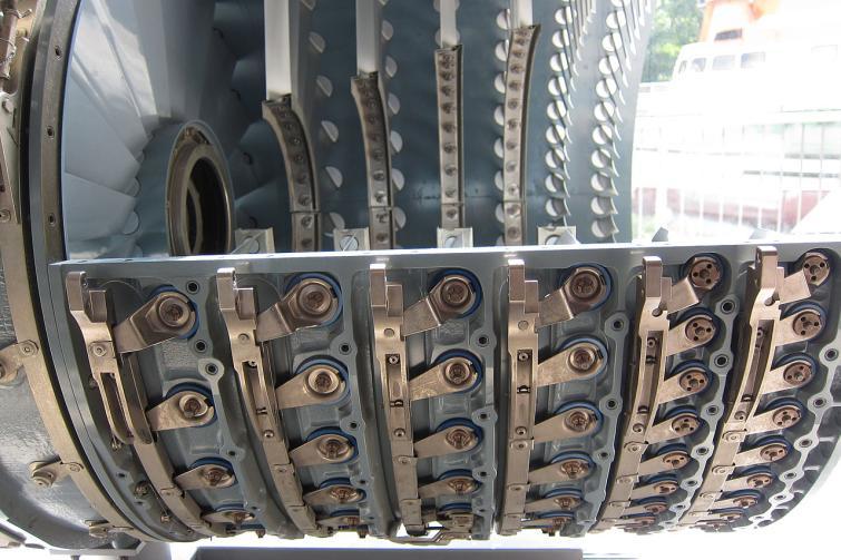
118 Stall Control [4/7]. Variable Stator [3/3] 축류압축기전단부몇개단에가변스테이터적용 가변스테이터는엔진회전속도에의해서자동적으로각 ( 피치 ) 조절 가변스테이터를적용하면작동기구로인하여압축기가복잡해지지만가스터빈전체적으로는다축식보다간단 Gas Turbines for Power Plants 3. Compressor 118 / 136
![Stall Control [5/7] 3.](/docs-images/93/111989371/images/119-0.jpg "Bleed Valve [1/]")
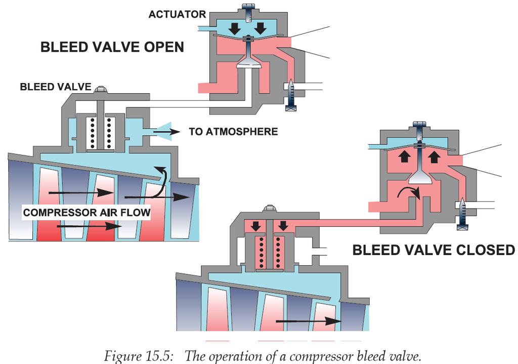
119 Stall Control [5/7] 3. Bleed Valve [1/] 축류압축기중간단또는후방에브리드밸브를설치하여기관시동시및저출력작동시이밸브가자동적으로열리도록하여압축공기를대기중으로방출 방출된공기량만큼축방향속도가작아짐에따라로터유입각이작아져서실속방지. w c w c u Gas Turbines for Power Plants 3. Compressor 119 / 136
120 Pressure Ratio Stall Control [6/7] 3. Bleed Valve [/] Bleed valves are used to dump compressed air. This is wasteful because the air has had work input. However, bleed valves are a lower cost and a more reliable option when compared to variable stators. Bleed air can, depending on the application point, lower the working line or even modify the surge line. As much as 5 to 5% of the compressed air may be bled off whilst starting. Consequently, the TIT increases significantly as the available cooling air reduces. Bleed valves are seldom used as a sole means of controlling the off design performance of the compressor and are mostly used in conjunction with variable geometries to optimize the benefits of them. Surge Line Working Line with Bleed Valve Closed Working Line with Bleed Valve Open N / T m T / p Gas Turbines for Power Plants 3. Compressor 10 / 136
![Stall Control [7/7] 4.](/docs-images/93/111989371/images/121-0.jpg "Multi-Spool Engine 축류압축기의안정운전범위는대개압력비 5 이하 다축식구조에서는압축기각축당압력비를 5 이하로제한가능 다축식으로하면고압력비와고효율가능 베어링증가에따라구조가복잡해지고중량도증가 HP Compressor (CF6-80C) HP Turbine (CF6-80E) Hot end drive shaft to generator IP")
121 Stall Control [7/7] 4. Multi-Spool Engine 축류압축기의안정운전범위는대개압력비 5 이하 다축식구조에서는압축기각축당압력비를 5 이하로제한가능 다축식으로하면고압력비와고효율가능 베어링증가에따라구조가복잡해지고중량도증가 HP Compressor (CF6-80C) HP Turbine (CF6-80E) Hot end drive shaft to generator IP Turbine Standard Annular Combustor Exhaust diffuser LP Compressor (MS6001FA) HPC inlet collector scroll case LPC exit diffuser scroll case Power Turbine Gas Turbines for Power Plants 3. Compressor 11 / 136
122 Basic Principles of an Axial Compressor Compressor Thermodynamics and Fluid Dynamics Dimensionless Numbers Basic Sizing Parameters Compressor Blade Shapes Degree of Reaction Compressor Losses Stall and Surge Centrifugal Compressor Developmental Trends Gas Turbines for Power Plants 3. Compressor 1 / 136


123 Principle Gas Turbines for Power Plants 3. Compressor 13 / 136
124 Generals Centrifugal compressors, they are still used on small gas turbines, are less efficient than axial compressors. Recent development have produced compression ratios as high as 10:1 from a single centrifugal compressor. When the pressure ratio exceeds 5:1, the flows entering the diffuser from the rotor are supersonic. This requires a special design of the diffuser. In a centrifugal compressor, the fluid is forced through the impeller by rapidly rotating impeller blades. The velocity of the fluid is converted into pressure, partially in the impeller and partially in the diffusers. Most of the velocity leaving the impeller is converted into pressure energy in the diffuser. 장점 1) 단당압축비가크다 - 10:1 (15:1 in a dual stage) ) 아이들에서최대출력까지넓은운전영역에서효율이좋다 3) 축류식에비해구조가간단하여제작이쉽고가격이저렴하다 4) 무게가가볍다 5) 시동파워가낮다 6) FOD 저항성이크다 1) 압축효율이낮다 단점 ) 동일추력의경우전면면적이커서저항이크다 3) 단사이의손실때문에 단이상으로하기곤란하다 Gas Turbines for Power Plants 3. Compressor 14 / 136
125 Centrifugal vs. Axial Compressor 1. The centrifugal and axial compressors are comparable in weight.. Aerodynamically, the axial compressor has better flow characteristics. Real fluid effects in centrifugal compressors are much larger, and therefore centrifugal ones have a lower efficiency. 3. The advantage of the centrifugal compressor lies in the simplicity of manufacture, especially when the turbomachine is miniaturized. 4. For moderate stagnation pressure ratios and low mass flow, centrifugal compressors are superior to the axial ones. The multistage centrifugal compressors involve larger aerodynamic losses. Thus, axial compressor is preferred for high pressure ratios and large mass flow. 5. Recent interest in centrifugal compressors for use in (a) small gas turbines for cars, (b) space power plants, (c) rocket engines, and (d) artificial heart pumps has revived the aerodynamic investigation of this machine. 6. For industrial applications, such as natural gas pumping and rocket engines, safety and reliability are more important and thus centrifugal compressors are sometimes preferred. 7. Gas turbines for power generation, where large mass flow and large pressure ratio are encountered, utilize axial flow compressors. Gas Turbines for Power Plants 3. Compressor 15 / 136

 Gas Turbines")
126 Multistage Centrifugal Compressor It is much more difficult to produce an efficient multistage centrifugal compressor because the flow has to be ducted back to the axis at each stage. Stage Impeller stage centrifugal compressors - Kawasaki PR = 10.5, Output = 1.68 MW th = 6.6% (blade cooling is possible because it adopts axial turbine although it is a small GT) Gas Turbines for Power Plants 3. Compressor 16 / 136


127 Combination Compressor A compressor has an axial-flow compressor combined with a centrifugal compressor as the last stage. Gas Turbines for Power Plants 3. Compressor 17 / 136
128 Basic Principles of an Axial Compressor Compressor Thermodynamics and Fluid Dynamics Dimensionless Numbers Basic Sizing Parameters Compressor Blade Shapes Degree of Reaction Compressor Losses Stall and Surge Centrifugal Compressor Developmental Trends Gas Turbines for Power Plants 3. Compressor 18 / 136
129 Developmental Trends [1/7] Increased pressure ratio Higher engine efficiency requires higher engine pressure ratio. Higher pressure ratios will also increase the number of stages and potentially longer rotors. The number of turbine stage has been changed from three to four as the pressure ratio increases. Variable stator has adopted to control compressor stall and to increase efficiency during part load operation. Increased specific flow Specific flow will continue to increase and approach aero-engine technology. Siemens: 80 kg/s (latest 50 Hz engine); MHI: 860 kg/s (J-class) GE: 745 kg/s (9FB.05), 440 kg/s (7FA), 558 kg/s (7H) The absolute maximum of today is around 1000 rpm, but this can be achieved only with multi -spools. GE and Alstom have upgraded compressor with aero-engine technology. All major OEMs have on-line compressor vibration measurements and associated protection system. Gas Turbines for Power Plants 3. Compressor 19 / 136
130 Developmental Trends [/7] Previous Designs New Designs Risk D double circular arc or NACA 65 profiles 3D or Controlled Diffusion-shaped Airfoil (CDA) profiles Large number of airfoils Reduced airfoils Repeating stages Stages unique Shorter chords Longer chords Low/modest aspect ratios High aspect ratios Large clearances Small clearances Low/modest pressure ratios Much high pressure ratios Low/modest blade loading per stage High blade loading per stage Wider operating margin Narrow operating margin Thicker leading edges Thinner leading edges Dry operation Wet operation Lower costs Higher costs Gas Turbines for Power Plants 3. Compressor 130 / 136
131 Pressure ratio Pressure Ratio GE Siemens Alstom WH/MHI GT4/GT6 501ATS 7H/9H E/9E 7F/9F 7EA/9EC V84./V F/701F 7FA/9FA GT13E GT11N 501G/701G V84.3 V84.3A/ V94.3A 501D5A /701D Gas Turbines for Power Plants 3. Compressor 131 / 136
132 Pressure ratio Pressure Ratio - GE 4 MS9001H MS7001H MS7001E MS7001C MS5001N MS5001P MS5001M MS7001B MS7001A MS9001B MS9001E MS6001B MS7001EA MS9001F MS7001EF MS9001FA Gas Turbines for Power Plants 3. Compressor 13 / 136
133 Air flow, lb/sec Air Flow - GE MS9001FA MS9001H MS7001H MS9001B MS9001E MS7001FA MS7001EF MS7001A MS500A MS5001M/R 00 MS5001N MS7001B MS500B MS5001P MS7001C MS7001E MS6001A MS6001B MS7001EA Gas Turbines for Power Plants 3. Compressor 133 / 136
134 Air mass flow, kg/sec TIT, C Air Flows and TITs TIT Air mass flow Gas Turbines for Power Plants 3. Compressor 134 / 136


135 High Pressure Packing Sealing became an important issue as the pressure ratio increases Brush seals Minimize air leakage Tolerant of misalignments More durable than labyrinth seals Gas Turbines for Power Plants 3. Compressor 135 / 136