Hydraulic Design of Sewer
|
|
|
- Elmer Wells
- 5 years ago
- Views:
Transcription
1 Module II Hydraulic Design of Sewer Tejasree Vemuri Asst. Prof. Dept. of civil Engineering SMGG
2 Course content Hydraulic formulae, maximum and minimum velocities in sewer, hydraulic characteristics of circular sewer in running full and partial full conditions, laying and testing of sewer, sewer appurtenances and network, Cleaning and Ventilation of Sewers.
3 Design of Sewers The hydraulic design of sewers and drains, means finding out their sections and gradients, is generally carried out on the same lines as that of the water supply pipes. However, there are two major differences between characteristics of flows in sewers and water supply pipes.
4 The sewage contain particles in suspension, the heavier of which may settle down at the bottom of the sewers, as and when the flow velocity reduces, resulting in the clogging of sewers. To avoid silting of sewers, it is necessary that the sewer pipes be laid at such a gradient, as to generate self cleansing velocities at different possible discharges. The sewer pipes carry sewage as gravity conduits, and are therefore laid at a continuous gradient in the downward direction up to the outfall point, from where it will be lifted up, treated and disposed of.
5 Hydraulic formulae 1. Chezy s formula where V= is the mean velocity [m/s], C= is the Chézy coefficient [m½/s], R= is the hydraulic radius (~ water depth) [m], i= is the bottom slope[m/m]. Constant (C) is very complex. Depends on size, shape and smoother roughness of the channel, the mean depth etc. C can be calculated by using Bazin s formula.
6 2. Bazin s formula C = [ (K/R1/2)] Where, K= Bazin s constant R= hydraulic radius Sr. No. Inside nature of the sewer K values Very smooth Smooth: bricks & concrete Smooth: rubble masonry Good, earthen material Rough: bricks & concrete Rough earthen material
7 3. Manning s formula V = velocity of flow (m/s) k =conversion factor of (ft/m)1/3 n =Manning coefficient Rh = hydraulic radius (m) S = slope of the water surface * The value of n is calculated by kutter s formula
8 4. Kutter s formula Where C = Chézy's roughness coefficient S = Friction slope R = Hydraulic radius (m,) n = Kutter's roughness (unit less) k1 =Constant (23.0 SI,) k2=constant ( SI,) k3= Constant (1.0 SI,)
9 5. Hazen William s formula where: V is velocity k is a conversion factor for the unit system k = for SI units) C is a roughness coefficient R is the hydraulic radius S is the slope of the energy line (head loss per length of pipe )
10 6. Crimp and Burge s formula V = R 2 / 3 S 1/ 2 Where, V = velocity of flow (m/s) R = hydraulic radius (m) S = slope of the water surface
11 Minimum Velocity The flow velocity in the sewers should be such that the suspended materials in sewage do not get silted up; i.e. the velocity should be such as to cause automatic selfcleansing effect. The generation of such a minimum self cleansing velocity in the sewer, at least once a day, is important, because if certain deposition takes place and is not removed, it will obstruct free flow, causing further deposition and finally leading to the complete blocking of the sewer.
12 Self clearing velocity To calculate minimum velocity of flow following formula is used. V= where, V= minimum velocity of flow in m/s. k= size of solids in sewage varying between 0.06mm f= Darcy s coefficient of friction (normally 0.03) es= specific gravity of solid material flowing in sewage, varies between 1.2 to 2.65 e= specific gravity of liquid in sewage (generally 1) g= gravitational acceleration cont. ds= dia of solid particles in mm
13 Maximum Velocity The smooth interior surface of a sewer pipe gets scoured due to continuous abrasion caused by the suspended solids present in sewage. It is, therefore, necessary to limit the maximum velocity in the sewer pipe. This limiting or nonscouring velocity will mainly depend upon the material of the sewer.
14 Effects of Flow Variation on Velocity in a Sewer Due to variation in discharge, the depth of flow varies, and hence the hydraulic mean depth (r) varies. Due to the change in the hydraulic mean depth, the flow velocity gets affected from time to time. It is necessary to check the sewer for maintaining a minimum velocity of about 0.45 m/s at the time of minimum flow (assumed to be 1/3rd of average flow).
15 The designer should also ensure that a velocity of 0.9 m/s is developed at least at the time of maximum flow and preferably during the average flow periods also. Moreover, care should be taken to see that at the time of maximum flow, the velocity generated does not exceed the scouring value.
16
17
18
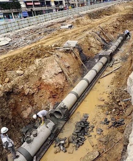
19 Laying of Sewer The basics of laying a residential sewer is lateral in the ground. You will need a starting elevation and an ending elevation. After the trench is excavated, when entering an open trench, the pipe layer prepares the trench bottom by removing loose dirt and grading the trench bottom to allow for proper flow of sewage within the pipe.
20 You need to ensure that the material beneath the pipe is solid so that the pipe does not "sag" after it is backfilled. Typically if the "original" ground beneath the new pipe is not disturbed and graded properly, the pipe will be adequately supported. If the original ground is over excavated, however, you will need to install compacted sand or gravel bedding beneath the pipe in order to support it.
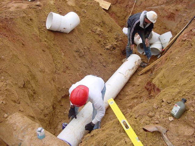
21 Once the ground is prepared, you lay the pipe on the prepared soil. In most cases, you should start on the low end of the run and work your way up to the connecting point. If you use "hub" pipe, that is, pipe with an integral pipe built into the pipe, you should lay your first pipe beginning on the low end of the run with the hub on the uphill side of the pipe.
22 If you are using PVC pipe, both ends of the pipe should be primed with purple primer prior to laying it. To connect the two ends of the pipe, you apply glue to the male and to the female ends of the pipe, being careful to not allow dirt to stick to the glued ends of the pipe. Insert the male end into the female end and spin the pipe. Hold the two pipes in place for ten seconds to ensure that they do not come apart.
23 Once the pipes are connected, you are ready to "bed" the pipe. This means that you should place sand or gravel around and over the pipe - enough to just cover the top of the pipe. Once this is complete, you compact the granular material around the pipe. It is important to pay attention to this compaction process so that the pipe does not lift while you are compacting.
24 Once the bedding process is complete, you are ready to move on the next pipe. It is important to note that as you install more pipe, you should be backfilling the trench behind you up to a safe level.
25
26
27 Testing of sewer The testing of sewers is necessary as any leakage, improper joints, straightness or obstruction of sewers may occur during laying of sewers. These defects may be removed or repaired after detection. So there are various tests by which these defects may be detected. These tests are :-
28 Water Test. Air Test. Smoke Test. Test For Obstruction.
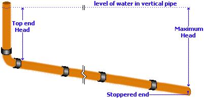
29 Water Test This test is carried out for sewer lines between two manholes. Plugging is done by rubber plug at its lower end. Rubber plug is connected with air blown. The upper end of sewer is plugged with a connection to the funnel. The sewer is filled with water and to maintain the required head, water level in the funnel is kept 2 m above the upper end.
30 This head varies with the material of sewer. In case of cast iron sewer, the head should be at 9m. The acceptable loss or head loss should not exceed 2 litres/cm of length of the sewer. To perform this test sufficient amount of water should be available.
31
32 Acceptable water loss Pipe Dia [mm] Max loss per metre in 30 mins [litres] >750 seek advice


33 Air Test When sufficient amount of water is not available, then air test is to be carried out.
34 Air is pumped into the pipeline, usually via a handpump with a control valve, until the reading on the manometer is around mm. The set-up is then left for 5-10 minutes to allow for temperature stabilisation within the pipe before the pressure is reduced to exactly 100mm on the manometer scale. The manometer is then monitored for a period of 5 minutes; the level of water in the manometer should not fall below the 75mm mark during this period.
35 This is deemed to be a 'pass' and the pipeline is declared satisfactory and can be backfilled. However, if the level in the manometer does fall below the 75mm mark, then the equipment should be checked and cleaned and the pipeline examined for leaks or defects. If any problems are identified, they should be rectified before re-testing.
36 Smoke Test The purpose of smoke testing is to find potential points of inflow and infiltration in the sanitary sewer system that could lead to high flows during a storm. Smoke testing forces smoke-filled air through a sanitary sewer line.

37 The smoke under pressure will fill the main line plus any connections and then follow the path of any leak to the ground surface, quickly revealing the source of the problem. Only enough force to overcome atmospheric pressure is required.
38 Test For Obstruction For straightness or obstruction of pipe, this test can be used. There are many methods for obstruction or straightness : 1. To check the obstruction of sewer pipe, a ball of suitable diameter is rolled down from upstream side. The diameter of ball should be less then the diameter sewer. If there is no obstruction, the ball can be taken out at downstream side.
39 2. The straightness can also be checked by placing a lamp at one end and a mirror at the other end. If the full circle of light is visible at other end, then the sewer is straight and there is no obstruction. If there is any obstruction within the sewer line, it can also be traced out.
40 Sewer Appurtenances Sewer appurtenances are the various accessories on the sewerage system and are necessary for the efficient operation of the system. They include man holes, lamp holes, street inlets, catch basins, inverted siphons, and so on.
41 Man-holes: Man holes are the openings of either circular or rectangular in shape constructed on the alignment of a sewer line to enable a person to enter the sewer for inspection, cleaning and flushing. They serve as ventilators for sewers, by the provisions of perforated man-hole covers. Also they facilitate the laying of sewer lines in convenient length. Man-holes are provided at all junctions of two or more sewers, whenever diameter of sewer changes, whenever direction of sewer line changes and when sewers of different elevations join together.
42

43
44 Special Man-holes Junction chambers: Man-hole constructed at the intersection of two large sewers. Drop man-hole: When the difference in elevation of the invert levels of the incoming and outgoing sewers of the man-hole is more than 60 cm, the interception is made by dropping the incoming sewer vertically outside and then it is jointed to the man-hole chamber.
45
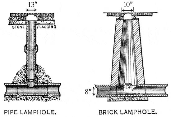
46 Flushing man-holes: They are located at the head of a sewer to flush out the deposits in the sewer with water. Lamp-holes: Lamp holes are the openings constructed on the straight sewer lines between two man-holes which are far apart and permit the insertion of a lamp into the sewer to find out obstructions if any inside the sewers from the next man-hole.

47 Flushing man-hole

48 Street inlets: Street inlets are the openings through which storm water is admitted and conveyed to the storm sewer or combined sewer. The inlets are located by the sides of pavement with maximum spacing of 30 m.

49 Catch Basins: Catch basins are small settling chambers of diameter cm and cm deep, which are constructed below the street inlets. They interrupt the velocity of storm water entering through the inlets and allow grit, sand, debris and so on to settle in the basin, instead of allowing them to enter into the sewers.
50 Inverted siphons: These are depressed portions of sewers, which flow full under pressure more than the atmospheric pressure due to flow line being below the hydraulic grade line. They are constructed when a sewer crosses a stream or deep cut or road or railway line. To clean the siphon pipe sluice valve is opened, thus increasing the head causing flow. Due to increased velocity deposits of siphon pipe are washed into the sump, from where they are removed.
51 Cleaning and ventilation of sewers Generally involves their cleaning to keep them free from any clogging and to carry the repairs to the damaged portions. It is necessary in order to make the sewerage system function efficiently. Frequent inspection, supervision, measuring the rate of flow, cleaning and flushing repairing the leaking joints
52 Ventilation of sewers Use of ventilating columns Use of ventilating manhole covers Proper design of sewers Use of mechanical devices Artificial ventilation
53

54
55 1 Page Module 7 : Hydraulic Design of Sewers and Storm Water Drains Lecture 8 : Hydraulic Design of Sewers and Storm Water Drains (Contd.) NPTEL IIT Kharagpur Web Courses
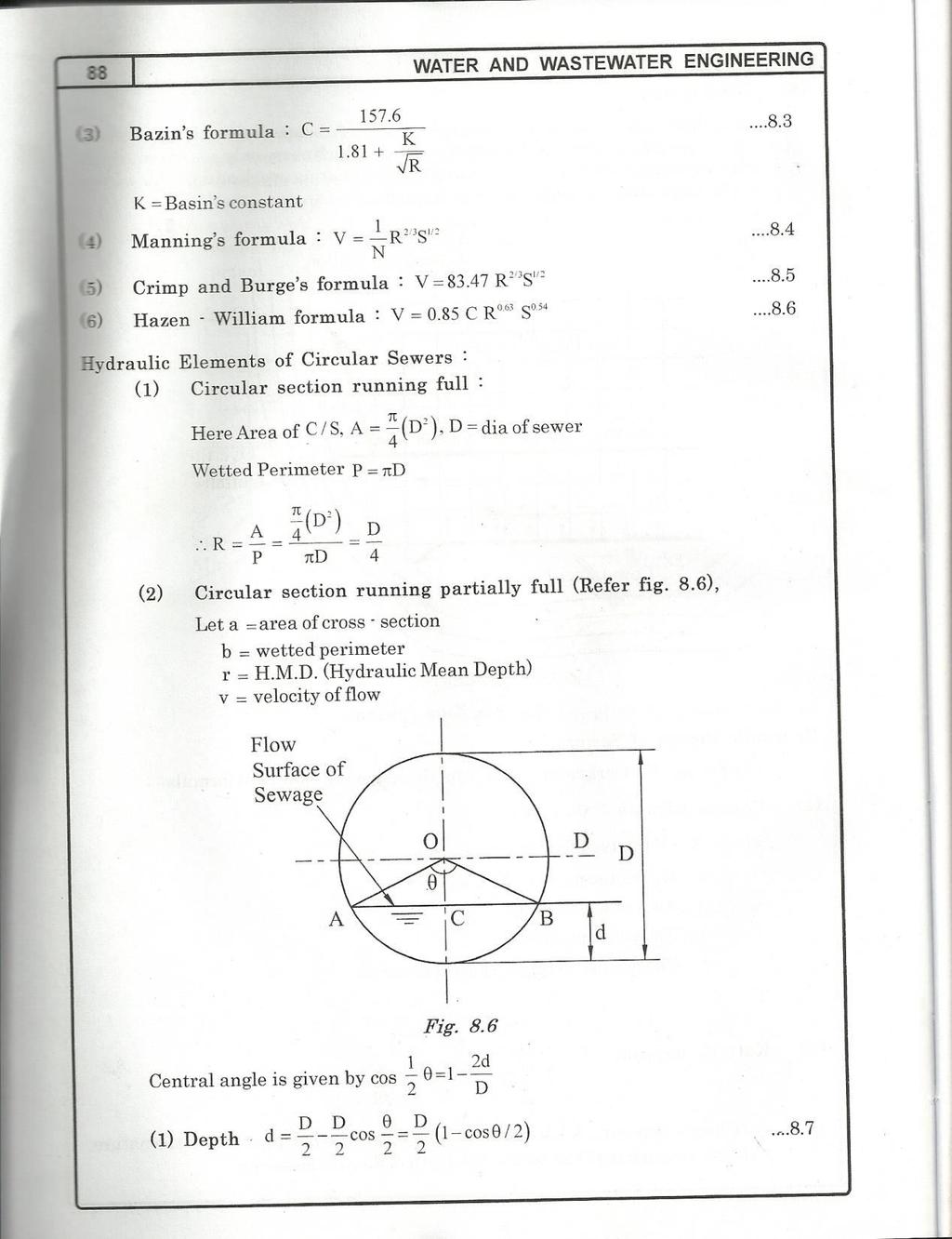
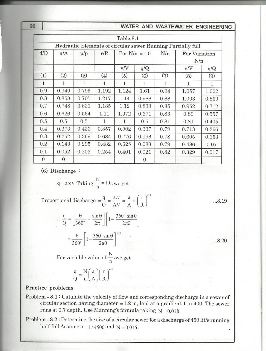
56 2 Page 7.9 Hydraulic Characteristics of Circular Sewer Running Full or Partially Full D α d Figure 7.1 Section of a circular sewer running partially full a) Depth at Partial flow D D d cos (6) b) Therefore proportionate depth d 1 1 cos D 2 2 (7) c) Proportionate area a Sin A p d) Proportionate perimeter: 360 P (8) (9) e) Proportionate Hydraulic Mean Depth r 360Sin 1 R 2 f) Proportionate velocity = (10) v N r 2/3 V n R2/3 (11) In all above equations except α everything is constant (Figure 7.1). Hence, for different values of α, all the proportionate elements can be easily calculated. These values of the hydraulic elements can be obtained from the proportionate graph prepared for different values NPTEL IIT Kharagpur Web Courses
57 3 Page of d/d (Figure 7.2). The value of Manning s n can be considered constant for all depths. In reality, it varies with the depth of flow and it may be considered variable with depth and accordingly the hydraulic elements values can be read from the graph for different depth ratio of flow. From the plot it is evident that the velocities in partially filled circular sewer sections can exceed those in full section and it is maximum at d/d of 0.8. Similarly, the discharge obtained is not maximum at flow full condition, but it is maximum when the depth is about 0.95 times the full depth. The sewers flowing with depths between 50% and 80% full need not to be placed on steeper gradients to be as self cleansing as sewers flowing full. The reason is that velocity and discharge are function of tractive force intensity which depends upon friction coefficient as well as flow velocity generated by gradient of the sewer. Using subscript s denoting self cleansing equivalent to that obtained in full section, the required ratios vs/v, qs/q and ss/s can be computed as stated below: (a) Hydraulic elements for circular sewer
58 4 Page (b) Hydraulic elements of circular sewer possessing equal selfcleansing properties at all depths Figure 7.2 Proportionate graph for circular sewer section (CPHEEO Manual, 1993) Consider a layer of sediment of unit length, unit width and thickness t, is deposited at the invert of the sewer (Figure 7.3). Let the slope of the sewer is degree with horizontal. The drag force or the intensity of tractive force ( ) exerted by the flowing water on a channel is given by: = γw. R. S Figure 7.3 A sediment particle moving on the sewer invert Where, γw = unit weight of water R = Hydraulic mean depth S = slope of the invert of the sewer per unit length (12)
59 5 Page With the assumption that the quantity of tractive force intensity at full flow and partial flow implies equality of cleansing, i.e., for sewers to be same self-cleansing at partial depth as full depth: =T Therefore, γw. r. ss = γw. R. S Hence, ss = (R/r) S Or ss R S r (13) (14) Therefore, vs N r V n R 2/3 ss S 1/ 2 (15) OR, by substituting r/r = S/ss 1/ 6 vs N r V n R (16) And 1/ 6 qs N a r Q n A R (17) Example: 2 A 300 mm diameter sewer is to flow at 0.3 depth on a grade ensuring a degree of self cleansing equivalent to that obtained at full depth at a velocity of 0.9 m/sec. Find the required grade and associated velocity and rate of discharge at this depth. Assume Manning s rugosity coefficient n = The variation of n with depth may be neglected. Solution: Manning s formula for partial depth v 1 2 / 3 1/ 2 r s n For full depth V 1 2 / 3 1/ 2 R S N Using V = 0.90 m/sec, N = n = and R = D/4 = 75 mm = m / 3 S 1 / NPTEL IIT Kharagpur Web Courses
60 6 Page S = This is the gradient required for full depth. and, Q = A.V = π/4 (0.3)2 x 0.90 = m3/s At depth d = 0.3D, (i.e., for d/d = 0.3) we have a/a = and r/r = (neglecting variation of n) Now for the sewer to be same self cleansing at 0.3 m depth as it will be at full depth, we have the gradient (ss) required as ss = (R/r)S Therefore, ss = S / = / = Now, the velocity vs generated at this gradient is given by N r vs V n R 1/ 6 = 1 x (0.684)1/6 x 0.9 = m/s The discharge qs is given by 1/ 6 N a r qs Q n A R qs = 1 x (0.258) x (0.939) x (0.064) = m3/s Example: 3 A combined sewer was designed to serve an area of 60 sq. km with an average population density of 185 persons/hectare. The average rate of sewage flow is 350 L/Capita/day. The maximum flow is 50% in excess of the average sewage flow. The rainfall equivalent of 12 mm in 24 h can be considered for design, all of which is contributing to surface runoff. What will be the discharge in the sewer? Find the diameter of the sewer if running full at maximum discharge. Solution: Total population of the area = population density x area = 185 x 60 x 102 = 1110 x 103 persons Average sewage flow = 350 x 11.1 x 105 Liters/day = x 106 L/day NPTEL IIT Kharagpur Web Courses
61 7 Page = 4.5 m3/sec Storm water flow = 60 x 106 x (12/1000) x [1/(24 x 60 x 60)] = 8.33 m3/sec Maximum sewage flow = 1.5 x average sewage flow = 1.5 x 4.5 = 6.75 m3/sec Total flow of the combined sewer = sewage flow + storm flow = = m3/sec Hence, the capacity of the sewer = m3/sec Hence, diameter of the sewer required at the velocity of 0.9 m/s can be calculated as π/4 (D)2 x 0.90 = m3/s Hence, D = 4.62 m Example: 4 Find the minimum velocity and gradient required to transport coarse sand through a sewer of 40 cm diameter with sand particles of 1.0 mm diameter and specific gravity 2.65, and organic matter of 5 mm average size with specific gravity 1.2. The friction factor for the sewer material may be assumed 0.03 and roughness coefficient of Consider k = 0.04 for inorganic solids and 0.06 for organic solids. Solution Minimum velocity i.e. self cleansing velocity Vs 8k ( Ss 1) gd ' f' Vs 8 x0.04 (2.65 1) x9.81x = m/sec say 0.42 m/sec Similarly, for organic solids this velocity will be m/sec Therefore, the minimum velocity in sewer = 0.42 m/sec Now, Diameter of the sewer D = 0.4 m Hydraulic Mean Depth = D/4 = 0.4/4 = 0.1 m Using Manning s formula: V = 1/n R2/3 S1/ = (1/0.012) x (0.1)2/3 x S1/2 NPTEL IIT Kharagpur Web Courses
62 8 Page S = 1/ Therefore, gradient of the sewer required is 1 in Example : 5 Design a sewer running 0.7 times full at maximum discharge for a town provided with the separate system, serving a population 80,000 persons. The water supplied from the water works to the town is at a rate of 190 LPCD. The manning s n = for the pipe material and permissible slope is 1 in 600. Variation of n with depth may be neglected. Check for minimum and maximum velocity assuming minimum flow 1/3 of average flow and maximum flow as 3 times the average. (for d/d = 0.7, q/q = 0.838, v/v = 1.12) Solution Average water supplied = x 190 x (1/24 x 60 x 60 x 1000) = m3/sec Sewage production per day, (considering 80% of water supply) = x 0.8 = 0.14 m3/sec Maximum sewage discharge = 3 x 0.14 = 0.42 m3/sec Now for d/d = 0.7, q/q = 0.838, v/v = 1.12 Therefore, Q = 0.42/0.838 = 0.5 m3/sec Now 1 D 2 D Q n 4 4 Q 1 D /3 S 1/ 2 D 4 2/ / 2 Therefore, D = 0.78 m V = Q/A = 1.04 m/sec Now, v/v = 1.12 Therefore v = 1.12 x 1.04 = 1.17 m/sec This velocity is less than limiting velocity hence, OK Check for minimum velocity Now qmin = 0.14/3 = m3/sec qmin/q = 0.047/0.5 = 0.09 From proportional chart, for q/q = 0.09, d/d = 0.23 and v/v = 0.65 Therefore, the velocity at minimum flow = 0.65 x 1.04 = 0.68 m/sec This velocity is greater than self cleansing velocity, hence OK dmin = 0.23 x 0.78 = 0.18 m NPTEL IIT Kharagpur Web Courses
63 9 Page Comment: If the velocity at minimum flow is not satisfactory, increase the slope or try with reduction in depth of flow at maximum discharge or reduction in diameter of the sewer. Assignment: Solve the above problem with population persons and pipe flowing 0.75 full at maximum discharge. The rate of water supply is 150 LPCD, n = 0.013, and permissible S = 1 in 600. NPTEL IIT Kharagpur Web Courses
64 1 Page Module 7: Hydraulic Design Of Sewers And Storm Water Drains Lecture 9 : Hydraulic Design Of Sewers And Storm Water Drains (Contd.) NPTEL IIT Kharagpur Web Courses
65 2 Page 7.10 Design of Storm Water Drains for Separate System Important points for design Storm water is collected from streets into the link drains, which in turn discharge into main drains of open type. The main drain finally discharges the water into open water body. As far as possible gravity discharge is preferred, but when it is not possible, pumping can be employed. While designing, the alignment of link drains, major drains and sources of disposal are properly planned on contour maps. The maximum discharge expected in the drains is worked out. The longitudinal sections of the drains are prepared keeping in view the full supply level (FSL) so that at no place it should go above the natural surface level along the length. After deciding the FSL line, the bed line is fixed (i.e. depth of drain) based on following consideration. a. The bed level should not go below the bed level of source into which storm water is discharged. b. The depth in open drain should preferably be kept less than man height. c. The depth is sometimes also decided based on available width. d. The drain section should be economical and velocities generated should be non-silting and non-scouring in nature. The drain section is finally designed using Manning s formula. Adequate free board is provided over the design water depth at maximum discharge Laying of Sewer Pipes Sewers are generally laid starting from their outfall ends towards their starting points. With this advantage of utilization of the tail sewers even during the initial periods of its construction is possible. It is common practice, to first locate the points where manholes are required to be constructed as per drawing, i.e., L-section of sewer, and then laying the sewer pipe straight between the two manholes. The central line of the sewer is marked on the ground and an offset line is also marked parallel to the central line at suitable distance, about half the trench width plus 0.6 m. This line can be drawn by fixing the pegs at 15 m intervals and can be used for finding out center line of the sewer simply by offsetting. The trench of suitable width is excavated between the two manholes and the sewer is laid between them. Further excavation is then carried out for laying the pipes between NPTEL IIT Kharagpur Web Courses
66 3 Page the next consecutive manholes. Thus, the process is continued till the entire sewers are laid out. The width of the trench at the bottom is generally kept 15 cm more than the diameter of the sewer pipe, with minimum 60 cm width to facilitate joining of pipes. If the sewer pipes are not to be embedded in concrete, such as for firm grounds, then the bottom half portion of the trench is excavated to confirm the shape of the pipe itself. In ordinary or softer grounds, sewers are laid embedded in concrete. The trench is excavated up to a level of the bottom embedding concrete or up to the invert level of the sewer pipe plus pipe thickness if no embedding concrete is provided. The designed invert levels and desired slope as per the longitudinal section of the sewer should be precisely transferred to the trench bottom. After bedding concrete is laid in required alignment and levels. The sewer pipes are then lowered down into the trench either manually or with the help of machines for bigger pipe diameters. The sewer pipe lengths are usually laid from the lowest point with their sockets facing up the gradient, on desired bedding. Thus, the spigot end of new pipe can be easily inserted on the socket end of the already laid pipe Hydraulic Testing of Sewers Test for Leakage or Water Test The sewers are tested after giving sufficient time for the joints to set for no leakage. For this sewer pipe sections are tested between the manholes to manhole under a test pressure of about 1.5 m water head. To carry this, the downstream end of the sewer is plugged and water is filled in the manhole at upper end. The depth of water in manhole is maintained at about 1.5 m. The sewer line is inspected and the joints which leak are repaired Test for Straightness of alignment This can be tested by placing a mirror at one end of the sewer line and a lamp at the other end. If the pipe line is straight, full circle of light will be observed. Backfilling the trench: After the sewer line has been laid and tested, the trenches are back filled. The earth should be laid equally on either side with layer of 15 cm thickness. Each layer should be properly watered and rammed. NPTEL IIT Kharagpur Web Courses
67 4 Page Questions 1. A 900 m long storm sewer collects water from a catchment area of 40 hectares, where 35% area is covered by roof (C=0.9), 20% area by pavements (C=0.8) and 45% area is covered by open plots (C=0.15). Determine the average intensity of rainfall and diameter of storm water drain. Assume the time of entry = 3 min; velocity at full flow = 1.45 m/sec; gradient of sewer = 0.001, and roughness coefficient = The intensity of rainfall, cm/h = 75/(t + 5). 2. Explain the importance of considering minimum and maximum velocity while designing the sewers. 3. Explain Self-cleansing velocity. 4. Explain important consideration while finalizing alignment and bed line of storm water drain. 5. Find the gradient required in sewer of 0.5 m diameter to maintain self cleansing velocity at flow full condition. 6. Write short notes on laying of sewer pipes. What hydraulic tests are conducted on the sewers? 7. Prepare notes on sewer maintenance. Answers Q. 1: Overall runoff coefficient = ; Average intensity of rainfall = 4.09 cm/h; Storm water quantity = m3/sec; and diameter of storm water drain = m NPTEL IIT Kharagpur Web Courses
68 1 Page Module 7: Hydraulic Design of Sewers and Storm Water Drains Lecture 7 : Hydraulic Design of Sewers and Storm Water Drains NPTEL IIT Kharagpur Web Courses
69 2 Page 7.1 General Consideration Generally, sewers are laid at steeper gradients falling towards the outfall point with circular pipe cross section. Storm water drains are separately constructed as surface drains at suitable gradient, either rectangular or trapezoidal section. Sewers are designed to carry the maximum quantity of sanitary sewage likely to be produced from the area contributing to the particular sewer. Storm water drains are designed to carry the maximum storm runoff that is likely to be produced by the contributing catchment area from a rain of design frequency and of duration equal to the time of concentration. 7.2 Requirements of Design and Planning of Sewerage System The sewerage scheme is designed to remove entire sewage effectively and efficiently from the houses to the point of treatment and disposal. Following aspects should be considered while designing the system. The sewers provided should be adequate in size to avoid overflow and possible health hazards. For evaluating proper diameter of the sewer, correct estimation of sewage discharge is necessary. The flow velocity inside the sewer should neither be so large as to require heavy excavation and high lift pumping, nor should be so small causing deposition of the solid in the sewers. The sewers should be laid at least 2 to 3 m deep to carry sewage from basement. The sewage in sewer should flow under gravity with 0.5 to 0.8 full at designed discharge, i.e. at the maximum estimated discharge. The sewage is conveyed to the point usually located in low-lying area, where the treatment plant is located. Treatment plant should be designed taking into consideration the quality of raw sewage expected and to meet the discharge standards. 7.3 Difference Between Water Supply Pipes and Sewer Pipes The major difference between the water distribution network and sewerage system is presented in the Table 7.1. Table 7.1: Comparison between the water distribution network and sewage collection system NPTEL IIT Kharagpur Web Courses
70 3 Page Water Supply Pipes It carries pure water. Sewer Pipes It carries contaminated water containing organic or inorganic solids which may settle in the pipe. It can cause corrosion of the pipe material. Velocity higher than self-cleansing is not To avoid deposition of solids in the pipes essential, because of solids are not present self-cleansing velocity is necessary at all in suspension. possible discharge. It carries water under pressure. Hence, the It carries sewage under gravity. pipe can be laid up and down the hills and Therefore it is required to be laid at a the valleys within certain limits. continuous falling gradient in the downward direction towards outfall point. These pipes are flowing full under pressure. Sewers are design to run partial full at maximum discharge. This extra space ensures non-pressure gravity flow. This will minimize the leakage from sewer, from the faulty joints or crack, if any. 7.4 Provision of Freeboard in Sewers Sanitary Sewers Sewers with diameter less than 0.4 m are designed to run half full at maximum discharge, and sewers with diameter greater than 0.4 m are designed to flow 2/3 to ¾ full at maximum discharge. The extra space provided in the sewers provides factor of safety to counteract against the following factors: 1. Safeguard against lower estimation of the quantity of wastewater to be collected at the end of design period due to private water supply by industries and public. Thus, to ensure that sewers will never flow full eliminating pressure flow inside the sewer. 2. Large scale infiltration of storm water through wrong or illegal connection, through underground cracks or open joints in the sewers. 3. Unforeseen increase in population or water consumption and the consequent increase in sewage production. NPTEL IIT Kharagpur Web Courses
71 4 Page Storm Water Drains Storm water drains are provided with nominal freeboard, above their designed full supply line because the overflow from storm water drains is not much harmful. Minimum of 0.3 m free board is generally provided in storm water drains. 7.5 Hydraulic Formulae for Determining Flow Velocities Sewers of any shape are hydraulically designed as open channels, except in the case of inverted siphons and discharge lines of pumping stations. Following formulae can be used for design of sewers. 1. Manning s Formula This is most commonly used for design of sewers. The velocity of flow through sewers can be determined using Manning s formula as below: v 1 2/3 1/2 r s n Where, (1) v = velocity of flow in the sewer, m/sec r = Hydraulic mean depth of flow, m = a/p a = Cross section area of flow, m2 p = Wetted perimeter, m n = Rugosity coefficient, depends upon the type of the channel surface i.e., material and lies between and For brick sewer it could be and 0.03 for stone facing sewers. s = Hydraulic gradient, equal to invert slope for uniform flows. 2. Chezy s Formula v C r1/2 s1/2 (2) Where, C is Chezy s constant and remaining variables are same as above equation. 3. Crimp and Burge s Formula v 83.5 r2/3 s1/2 (3) 4. Hazen- Williams Formula V = C R0.63 S0.54 (4) NPTEL IIT Kharagpur Web Courses
72 5 Page The Hazen-Williams coefficient C varies with life of the pipe and it has high value when the pipe is new and lower value for older pipes. For example for RCC new pipe it is 150 and the value recommended for design is 120, as the pipe interior may become rough with time. The design values of C; for AC pipes, Plastic pipes, CI pipes, and steel lined with cement are 120, 120, 100, and 120, respectively. Modified Hazen-William s equation is also used in practice. 7.6 Minimum Velocity: Self Cleansing Velocity The velocity that would not permit the solids to settle down and even scour the deposited particles of a given size is called as self-cleansing velocity. This minimum velocity should at least develop once in a day so as not to allow any deposition in the sewers. Otherwise, if such deposition takes place, it will obstruct free flow causing further deposition and finally leading to the complete blocking of the sewers. This minimum velocity or self-cleansing velocity can be worked out as below: Vs 8K (Ss 1)g.d ' f' Where, (5) K= constant, for clean inorganic solids = 0.04 and for organic solids = 0.06 f' = Darcy Weisbach friction factor (for sewers = 0.03) Ss = Specific gravity of sediments g = gravity acceleration d' = diameter of grain, m Hence, for removing the impurities present in sewage i.e., sand up to 1 mm diameter with specific gravity 2.65 and organic particles up to 5 mm diameter with specific gravity of 1.2, it is necessary that a minimum velocity of about 0.45 m/sec and an average velocity of about 0.9 m/sec should be developed in sewers. Hence, while finalizing the sizes and gradients of the sewers, they must be checked for the minimum velocity that would be generated at minimum discharge, i.e., about 1/3 of the average discharge. While designing the sewers the flow velocity at full depth is generally kept at about 0.8 m/sec or so. Since, sewers are generally designed for ½ to ¾ full, the velocity at designed discharge (i.e., ½ to ¾ full) will even be more than 0.8 m/sec. Thus, the minimum velocity generated in sewers will help in the following ways: NPTEL IIT Kharagpur Web Courses
73 6 Page Adequate transportation of suspended solids, Keeping the sewer size under control; and Preventing the sewage from decomposition by moving it faster, thereby preventing evolution of foul gases. 7.7 Maximum Velocity or Non-scouring Velocity The interior surface of the sewer pipe gets scored due to the continuous abrasion caused by suspended solids present in sewage. The scoring is pronounced at higher velocity than what can be tolerated by the pipe materials. This wear and tear of the sewer pipes will reduce the life span of the pipe and their carrying capacity. In order to avoid this, it is necessary to limit the maximum velocity that will be produced in sewer pipe at any time. This limiting or nonscouring velocity mainly depends upon the material of sewer. The limiting velocity for different sewer material is provided in Table 7.2. Table 7.2 Limiting or non-scouring velocity for different sewer material Sewer Material Limiting velocity, m/sec Vitrified tiles Cast iron sewer Cement concrete Stone ware sewer Brick lined sewer The problem of maximum or non-scouring velocity is severe in hilly areas where ground slope is very steep and this is overcome by constructing drop manholes at suitable places along the length of the sewer. 7.8 Effect of Flow Variations on Velocities in a Sewer The discharge flowing through sewers varies considerably from time to time. Hence, there occur variation in depth of flow and thus, variation in Hydraulic Mean Depth (H.M.D.). Due to change in H.M.D. there occur changes in flow velocity, because it is proportional to (H.M.D.)2/3. Therefore, it is necessary to check the sewer for minimum velocity of about 0.45 m/sec at the time of minimum flow (1/3 of average flow) and the velocity of about 0.9 to 1.2 m/sec should be developed at a time of average flow. The velocity should also be checked for limiting velocity i.e. non-scouring velocity at the maximum discharge. NPTEL IIT Kharagpur Web Courses
74 7 Page For flat ground sewers are designed for self-cleansing velocity at maximum discharge. This will permit flatter gradient for sewers. For mild slopping ground, the condition of developing self-cleansing velocity at average flow may be economical. Whereas, in hilly areas, sewers can be designed for self-cleansing velocity at minimum discharge, but the design must be checked for non-scouring velocity at maximum discharge. NPTEL IIT Kharagpur Web Courses
75 8 Page Example: 1 Design a sewer for a maximum discharge of 650 L/s running half full. Consider Manning s rugosity coefficient n = 0.012, and gradient of sewer S = Solution Q = A.V 0.65 = (πd2/8) (1/n) R2/3 S1/2 R = A/P Solving for half full sewer, R = D/4 Substituting in above equation and solving we get D = 1.82 m. Comments: If the pipe is partially full it is not easy to solve this equation and it is time consuming. NPTEL IIT Kharagpur Web Courses