Thermal Hydraulics of Severe Accidents (TERMOSAN)
|
|
|
- Alexandra Shelton
- 5 years ago
- Views:
Transcription

1 VTT TECHNICAL RESEARCH CENTRE OF FINLAND LTD Thermal Hydraulics of Severe Accidents (TERMOSAN) SAFIR2014 Final Seminar March, 2015, Espoo, Finland Tuomo Sevón, Anna Nieminen, Veikko Taivassalo, Karri Penttilä
2 Introduction Objective: improve modeling capabilities on thermal hydraulics of severe accidents Passive containment cooling system experiments calculated with MELCOR and ASTEC codes Participated international OECD THAI-2 research program Developed CFD models of hydrogen combustion experiments during spray operation In-vessel melt retention at VVER-440 analyzed with ChemSheet and ASTEC codes Models of the Fukushima accident developed with MELCOR code 2


3 Modeling of Passive Containment Cooling Systems (PCCS) Earlier: developed MELCOR models of vertical PCCS Obtained very good results, better than 10 % accuracy ABWR reactor type has PCCS with horizontal tubes Condensation in horizontal tubes more challenging to calculate Cylinder symmetry is lost Condensate film thicker at bottom of tube Figures: Incropera & DeWitt: Fundamentals of heat and mass transfer 3
4 MELCOR Calculation of Steady-State Condensation in a Horizontal Tube 60 Calculated heat transfer (kw) % 20 % Default Modified Re limits Measured heat transfer (kw) 4

5 Calculation of Lappeenranta University of Technology PCCS Test Transient experiments with U-shaped tubes made in PCCS project in SAFIR VTT calculated PCC-06 test with MELCOR and ASTEC in TERMOSAN project Both codes underestimated condensation by about 50 % Slightly better results with Apros in ESA project Reason for poor results unknown Work should continue, but did not get funding in SAFIR2018 5

6 Behavior of Hydrogen and Iodine: OECD THAI-2 Research Program Finland participated THAI-2 in the frame of TERMOSAN project Test facility located in Eschborn, Germany Experiments made on: Interaction between gaseous iodine and aerosol particles Hydrogen recombiners Hydrogen deflagration during containment spray operation Veikko Taivassalo calculated deflagration experiments with Fluent CFD code 6

7 In-Vessel Melt Retention Loviisa: retention of molten corium in RPV by external cooling Heat flux depends on melt layering Methods for modeling a three-layer melt pool were developed in TERMOSAN project Chemical equilibrium was calculated with ChemSheet by Karri Penttilä Fortum has used these results in their own safety analyses Heat transfer was calculated with ASTEC by Anna Nieminen 7
8 Analysis of Fukushima Accident Accidents at Fukushima Units 1, 2, and 3 calculated with MELCOR code in TERMOSAN project Calculation models developed from scratch, using publicly available plant data Objectives: 1. Improving expertise in severe accident modeling 2. Gaining better understanding of events during the accident 3. Getting insights into capabilities and weaknesses of MELCOR 8
9 Accident Progression at Fukushima Reactors Unit 1: Cooled by isolation condenser until tsunami arrival All cooling failed when AC and DC power was lost Core uncovery started less than 3 hours after earthquake Unit 2: Cooled by turbine-driven pump for 66 hours Surprisingly long operation without AC and DC power Core uncovery started about 75 hours after earthquake Unit 3: Cooled by turbine-driven pumps for about 35 hours DC power was available from batteries Core uncovery started about 36 hours after earthquake 9


10 Calculated Final State of Fukushima Reactors Unit 1: RPV failed, all fuel discharged to containment Unit 2: RPV not failed, 13 % of fuel relocated to bottom of RPV Unit 3: RPV failed, 70 % of fuel discharged to containment 10
11 Calculated Radioactive Release to Environment at Fukushima Noble gas inventory almost completely released at all three units Calculated cesium release: 0.05 % from Unit 1, 0.08 % from Unit 2, 0.95 % from Unit 3 Largest release from Unit 3 because of early containment venting, no time for deposition of aerosols Containment venting systems not equipped with filters Hydrogen explosions in reactor buildings had only small effect on release to environment Still large uncertainties in calculated releases Models will be updated when more information becomes available 11
12 Calculated Timing of Releases to Environment, Compared with Timing of Measured Dose Rate Measured dose rate (µsv/h) Unit 1 venting Unexplained peak Unit 3 venting Unit 1 containment leak increase Unit 3 explosion Unit 2 containment leak increase Time (h) 1E+1 1E+0 1E-1 1E-2 1E-3 1E-4 1E-5 1E-6 Calculated noble gas release rate (% of inventory / h) 12
13 Conclusions from Fukushima Calculations Units 1 and 3: Molten fuel probably discharged to containment Unit 2: All fuel probably still inside reactor Unverified because camera inspection of reactors not yet possible Largest release to environment from Unit 3 because unfiltered venting made at early phase Calculated timing of release corresponds well to measured peaks of radiation dose rate at plant area Stratification of wetwell water has large effect on containment pressure but difficult to calculate Behavior of safety systems outside their design conditions difficult to predict 13
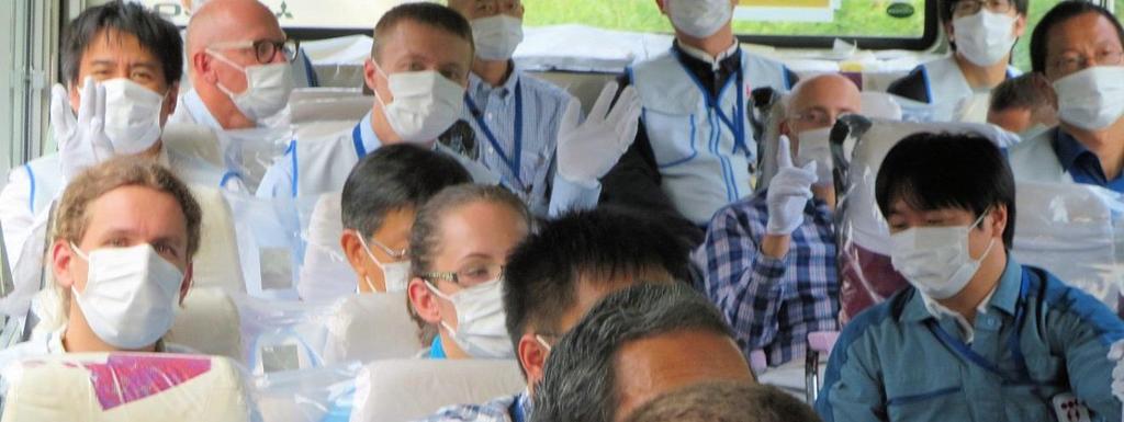
14 Participated on Fukushima Plant Tour 14
15 How TERMOSAN Project Has Developed Expertise for Solving Safety Issues TERMOSAN project pays Finland s annual MELCOR license fee Provides MELCOR license for VTT, TVO, Fortum, and Fennovoima Developed analysis methods for horizontal passive containment cooling systems (similar to ABWR) Results not yet satisfactory, more work needed Better knowledge of hydrogen and iodine behavior from OECD THAI-2 experiments and their CFD calculations Methods for in-vessel melt retention analysis Fortum has used these results in safety analyses of Loviisa Expertise in severe accident modeling significantly improved by developing models of three real accidents at Fukushima 15


16 TECHNOLOGY FOR BUSINESS