HY-PRO Filtration Introduction for. by Patrick A.J.M. Kreutzer
|
|
|
- Bonnie Nelson
- 5 years ago
- Views:
Transcription

1 HY-PRO Filtration Introduction for by Patrick A.J.M. Kreutzer 1
2 Topic of the presentation Introduction / Opening HyPro Filtration Introduction Contamination ISO CODE Product Range Overview HyPro Filtration Dynamic Filter Efficiency Water Ingression Acid Scavenging system 2

3 Company Overview Hy-Pro Filtration Anderson, Indiana H.Q. Indianapolis, USA Production Facility Vancouver WA Corporate headquarters + laboratory + training facility Filter elements + filter assemblies manufacture Primary element stocking warehouse Off-line contamination solutions (portable + dedicated) manufacture Focused Activity Filtration & Conditioning Lube & Hydraulic Systems Diesel Oil and Fuel 3


4 Company Overview, Capabilities Anderson, IN Corporate headquarters Filter element production Filter assemblies Small contamination solutions equipment Hy-Pro laboratory UL approved control panels Hy-Pro Training facilities 4


5 Filter Element Production Anderson, IN 5


6 Off-line Systems Production Anderson, IN 6


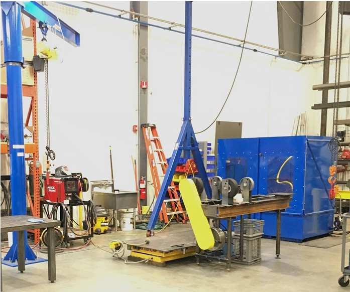


7 Metal Fabrication Anderson, IN 7
 ISO")

 test")
8 Hy-Pro Laboratory Anderson, IN Element integrity (bubble point) ISO Code KF (H 2 O) Microscope / Patch MPC Varnish Element forensic Contaminant analysis Partner labs Dynamic Filter Efficiency (DFE) test bench HY-PRO 8


9 Capabilities Hy-Pro West Vancouver, WA Vacuum dehydration purifiers High flow coalesce Diesel conditioning systems Large custom contamination solutions West coast stocking location Equipment rental fleet & service Contamination solutions support Electrical panels (UL, CUL, CE, ATEX, IEC) 9


10 Capabilities Hy-Pro West Vancouver, WA 10


11 Capabilities Hy-Pro West Vancouver, WA 11
12 Thanks End of this part of the presentation Next Presentation: Contamination 12
 7. Act as a dielectric fluid (transformers) 8.")
13 Lubrication Functions 1. Reduce friction and wear 2. Carry away heat 3. Seal against contaminants 4. Prevent rust and corrosion 5. Remove contaminants Hard,Soft,Water,Gas 6. Transmit Power (hydraulics) 7. Act as a dielectric fluid (transformers) 8. Dampen shock (shock absorbers) 13
14 Continuous development of equipment within the industry (OEM) made it necessary to develop also modern lubricants (Turbine Oils) Turbine oils have changed continuously to meet the operational requirements of new generation turbine technology Requirements for modern oils increased, driven by stringent specifications like: Change of Operational conditions of the installation Increasing bearing temperature Higher bearing load Lubrication Development Smaller lubrication oil reservoir ect. Changing OEM requirements New turbine oil products (different base oils / synergistic mixtures + different additives) 14
15 Lubrication Groups Group I : Group II, III, IV, V : Original group, base oil (base stock) created by further development of oil (hydro-cracked) Development required by equipment OEM Lubricant = base stock + additive package (AO) Additive (AntiOxidants) is protection package for depletion of oil Mineral Oil HydroCarbon chains cleaner, more structured depending on Group Level The higher the group level the better the prevention towards oil degradation Mineral Oil : Group I,II,III Synthetic Oil: Group IV,V 15 Basis : Napthenic, Parafinic, Aromatic Basis : Synthetic Hydrocarbons (SHC) build out of Poly Alpha Olifins Monomers (PAO)
16 Lubrication Depletion Mechanism Oxidation Thermal Degradation Contaminants Other Air Spark Discharge Water Additive Drop-Out Metal Catalysts Micro- Dieseling Solids Formulation Quality Ultraviolet Hot Spots Gas Incompatible fluids 16

17 Environment 17

18 Contamination classification 18
19 Contamination classification Soft Contaminants Fluid degradation by-products comprised of degraded base oil and depleted additives. Can be caused by many factors including oxidation, thermal degradation, additive depletion, additive/base-stock incompatibilities. Characteristic size < 1 micron Hard Contaminants Dirt, Debris, Wear Particles, Characteristic size > 2 micron. But can be much smaller as in the case of micro-dieseling. Smaller than 0.45 micron Liquid Contaminants Water, Incompatible Lubricants or other Fluids from Ingression or Process Gaseous Contaminants - Ingression or Process 19

20 Grain of salt 100 Microns Limit of visibility 40 Microns White blood cells 25 Microns Red blood cells 8 Microns Bacteria 2 Microns 1 micron = = 1 micrometer 1 micron = 0, meter = 0,001 mm 20
21 Thanks End of this part of the presentation Next Presentation: ISO Codes 21


22 ISO Codes / Contamination / Maintenance Filtration: cost is < 3% of total contamination cost. Hidden costs, below the surface Increase Downtime Component repair, replacement Safety issues Maintenance labor Environmental impact Decrease Reliability Fluid life Production Useful fluid life 22


23 Cleanliness saves contamination cost Increase Component life Hydraulic performance Safety Fluid Life Decrease Downtime Labor Filter usage Failures Ingression 23
24 ISO Code - Cleanliness ISO 4406:1999 Code Chart Range Code More than Particles per Milliliter Up to & including Particle Size Particles per ml Understanding ISO Codes ISO 4406 Code range ISO Code 4μ [c] ~ μ [c] μ [c] ~ μ [c] μ [c] ~ μ [c] μ [c] μ [c] 2 The ISO cleanliness code (per ISO ) is used to quantify particulate contamination levels per milliliter of fluid at 3 sizes 4µ [c] / 6µ [c] / 14µ [c]. The ISO code is expressed in 3 numbers (example: 24/22/19). Each number represents a contaminant level code for the correlating particle size. The code includes all particles of the specified size and larger. It is important to note that each time a code increases the quantity range of particles is doubling and inversely as a code decreases by one code the level of contaminant is cut in half. 24
25 Thanks End of this part of the presentation Next Presentation: Product Range Overview 25
26 Partnership EPT Calgary based knowledge guided company with over 25 years of experience in advance science of lubrication maintenance and reliability for critical applications. Strategy Partnership between EPT and HY-PRO: Design, Engineering, Oil Analysis Sales Dedicated Customer Solutions EPT patented technologies: Ion Charged Bonding (ICB ), Soluble Varnish Removal (SVR ) Electrostatic Contamination Removal (ECR ), and Total Moisture Removal (TMR ) EPT Technologies have tens of millions of hours of proven performance on super-critical applications such as airports, aircraft carriers, gas turbines, and EHC systems at some of the largest power plants in the world. Markets : e.g. Power Generation, Manufacturing, Heavy Industries ect. 26
27 Dynamic Filter Efficiency All Hydraulic and Lubrication systems have a critical contamination tolerance level that is often defined by, but not limited to, the most sensitive system components, such as Servo Valves or high speed Journal Bearings. Component manufactures specify fluid cleanliness level as per ISO 4406:1999 for optimum performance and predictable life. AN OPERATING SYSTEM IS AT RISK WHENEVER THE CRITICAL CONTAMINATION LEVEL IS EXCEEDED. Contamination levels determine the individual component wear rate (hence useful life), and its ability to perform as intended. Filters are expected to maintain contamination below the critical tolerance levels. System design, filter performance and maintenance practices largely determine the contamination levels in a system. 27
28 Dynamic Filter Efficiency Filter performance in a dynamic operating system is variable and based upon flow rate and flow density, changes in flow rate, viscosity, fluid and structure born vibration, contamination levels, ingression rate, and several other conditions. All filters are subject to a form of system dynamics: Hydraulic Filters frequent and rapid changes in flow rate accompanied by operational frequency changes Lubrication Filters Dynamic conditions during start up and shut down Key characteristics of filter performance Capture efficiency how effective a filter captures the particles Retention efficiency how effectively a filter retains the particles it has collected IF NOT PROPERLY DESIGNED AND APPLIED A FILTER CAN BECOME ONE OF THE MOST DAMAGING SOURCES OF CONTAMINATION IN A SYSTEM 28
29 Dynamic Filter Efficiency In response to contamination issues with customer hydraulic and lubrication systems Hy-Pro Filtration along with SSI, Inc., developed a test method that provides information on the varying contamination levels in operating systems. This is based upon bridging the gap between the Laboratory and the Real World in Filtration Performance and ISO Codes An alternative approach to multi-pass filter performance testing and development of the industry standard ISO

30 Efficiency Actual systems operation Movement = Work Work Needs Pressure Work Needs Flow Constant Flow? Constant Pressure NO STATIC DYNAMIC 30
31 Dynamic Filter Efficiency Manufacturers of filter assemblies and filter elements use the industry standard protocol ISO multi pass method, to rate the efficiency and dirt holding capacity of filter elements under ideal laboratory conditions. This ISO multi pass test was updated in 1999 from ISO The standard provides a good repeatable test method where identical filters should produce like results when tested on a variety of Test Rigs. 31

32 ISO Multi Pass Filter Test Fixed flow rate. Dynamic Filter Efficiency Small amounts of fluid are removed before and after the filter for particle counting to calculate efficiency expressed as the Filtration ration (Beta) Known contaminant added into the system Constant recirculation MIL-H-5606 Fluid Test Filter 32
33 Dynamic Filter Efficiency : Beta Ratio (β) Filtration Terms β x = quantity of particles xµ upstream of filter quantity of particle xµ downstream of filter 10 micron = Particle size used in the calculation Upstream Particles = 400 Downstream Particles = 2 β 10 = β 10 =
34 Dynamic Filter Efficiency : Efficiency Filtration Terms % Efficiency (ε) ε = {(β x 1) / β x } x 100 β10 = 200 ε = {(β10 1) / β10 } x 100 ε = {(200 1) / 200} x 100 ε = % % Efficiency (ε) % Efficiency (ε) ε = 1 β x -1 β 10 = 200 ε = ε = % 34
35 Beta Ratio vs. Filter Efficiency Filtration Terms HY-PRO Absolute Nominal β Ratio Efficiency # upstream # downstream β x % 100, β x % 100, β x % 100, β x % 100, β x % 100, β x % 100, β x % 100, β x % 100,000 1,000 β x % 100,000 1,333 β x % 100,000 1,667 β x % 100,000 2,500 β x % 100,000 5,000 β x % 100,000 10,000 β x % 100,000 25,000 β x % 100,000 50,000 35
36 Dynamic Filter Efficiency The DFE test goes further than the current industry standard, by inducing dynamic duty cycles and measuring real time performance, before during and after the cycles. DFE multi pass testing quantifies both capture and retention efficiency in real time so that a prediction can be made of the worst case fluid cleanliness with average cleanliness. The DFE test utilizes upstream and downstream particle counters, test filter and injection point much like ISO The DFE flow rate is hydrostatically controlled to make flow changes quickly, while maintaining full system flow through the test filter. Particle counter sensor flows remain constant during all particle counts, which ensures that the fluid counted is representative of the system contamination level. Counts are taken before, during and after each flow change. The total number is determined by the duty cycle of the specific test. The efficiency results are reported as Filtration Ration (Beta), efficiency percent and actual particle levels per milliliter. The rapid particle counting and timing of DFE allows the user to analyse and understand both capture and retention efficiency of each filter tested. 36
37 Dynamic Filter Efficiency ISO vs. DFE Multi-pass Test: ISO SS Testing Pump flow is fixed by tester 4 samples minimum required Dynamic Filter Efficiency Test: Modified ISO Testing Pump flow varies (50% - 100%) Transition 50% Flow to 100% Flow 100% Flow Transition to 50% Flow Repeat Sampling is real time throughout test (100+ samples drawn) 37
38 Dynamic Filter Efficiency DFE Rated Filter Elements... DFE Rated Filter Elements Achieving a Higher Standard!!! Achieving a Higher Standard!!! Products designed to a higher standard High efficiency capture & retention Media optimized for Low ISO CODES not beta Reliable system operation Improve plant efficiency & profitability You can t fix a problem that you don t realize exists 38
39 DFE Rated Filter Elements Filter Elements & Media: DFE Dynamic Filter Efficiency Cellulose to Glass Upgrades Lube Design Filter Elements Dynafuzz Stainless Steel Fiber Media NSD Non-Spark Discharge Filter Elements Water Removal Filter Elements Turbo-TOC Filter Element Upgrade Upgrades (Not Replacements) For All Major Filter OEM Hydraulic and Lubrication Filter Elements Modifief ISO testing principle -> DFE β [x] > 1000 Over Interchange Upgrade Elements & critical interchanges Flexible manufacturing Hot Order Response; Delivery in hours/days not in weeks Extensive element stock levels Pall Hydac Parker Schroeder Donaldson Stauff Mahle Taisei Kogyo Internormen Indufil Moog Kaydon Hilco Eppensteiner Fleetguard Fairey Arlon Caterpillar Nugent Porous Media PTI Western Vickers Many more 39


40 Filter Assemblies & Accessories In-Tank Duplex Filter In-Tank Assemblies Low Pressure Assemblies Medium Pressure Assemblies High Pressure Assemblies Duplex Filter Assemblies Reservoir Accessories Test Kits & Equipment Low Pressure Medium Pressure Reservoir Accessories Spin-On Hy-Dry High Pressure 40
41 Fluid Condition Equipment Off-Line Filter Systems: CFU FPL FC CFU Compact Filter Unit FPL Filter Panel FC Filter Carts FSL High Viscosity Filter Systems FSLD Duplex High Viscosity Filter Skids FSW Wall Mounted High Viscosity Filter System FCL High Viscosity Filter Carts HS Heater Skid FSL FSDL FSW FCL HS 41
42 Water Contamination; the basics Water is one of most common and damaging contaminants found in lube and hydraulic oils Continuous or periodic high water results in damage such as: Metal etching (corrosion) Wear in hydraulic components Dielectric strength loss Fluid breakdown Additive depletion Oil oxidation Reduction of lubricating properties Oil is like a sponge, it will accept water until it can t accept any more. 42 The process of water contamination will then continue with free water.
43 Water Contamination; the basics When water/oil solution cools down, depending on temperature, you may see some free water separation Effect of moisture/water in your oil system can reduce on-stream plant availability Bearing life and critical component life are also reduced by moisture levels above and within saturation point Degree of contamination and type of water contamination is determining the best method of removal: Dissolved water Emulsified water Free water 43

44 Water Contamination; the basics Dissolved water Dissolved water is the state at which individual water molecules (not visible to the naked eye) are dispersed throughout a fluid. Dissolved water accrues below the fluid s saturation point. Fluid with only dissolved water in it will have a bright, clear appearance. 44

45 Water Contamination; the basics Emulsified water Once the dissolved water s concentration has exceeded the saturation point of the fluid, microscopic water droplets will start to form an emulsion which is suspended within the fluid. Fluid samples containing emulsified water will have a cloudy, hazy appearance (mayonnaise) 45

46 Water Contamination; the basics Free water Free water is formed once the emulsified water has reached a concentration at which it starts a separation phase and large water droplets begin to fall out of solution. Fluid samples containing free water will have a cloudy, hazy appearance. 46 As the sample settles, the free water will fall out to form a separated layer on the bottom of the sample.
47 Water Contamination; the basics Free and dissolved water in hydraulic and lub systems leads to: Bearing fatigue Accelerated abrasive wear (friction) Corrosion of metal surface Increased metal conductivity Variance in viscosity Lost of lubrication capacity Additive package breakdown Sources could be: Reservoir leakage Worn actuator seals Heat exchanger leakage New oil 47


48 Water Contamination; the basics DISSOLVED Water Oil appears bright and clear; Difficult to separat EMULSIFIED Water Very small droplets dispersed in oil. Oil viscosity may go UP (like mayonnaise). Tiny amounts of detergent engine oil can contaminate industrial oils. FREE Water Large drops that readily settle out. 48
49 Water Contamination; the basics Water Contamination Removal Methods: Water Absorbing Filter Elements Only for Free water Usable for all lubricants Needs replacement within a certain period. Head Space Dryer Usable for all dissolved, emulsified and free water Usable for all lubricants Control water ingression via reservoir Coalesce Systems Only Free Water and a small portion of emulsified water Usable for Turbine oils, Compressor oils and Diesel oils Limited to oils not having aggressive additive package like AW and/or EP additive Vacuum Dehydration Systems VUD20 Usable for all lubricants, including phosphate esters Usable for dissolved, free and emulsified water Old tech. is Centrifuge. Only free water removal, sensitive to maintenance and very costly 49


50 Water Contamination; the problem Downtime Accelerated wear Premature Bearing & Component Failure Viscosity fluctuation Oxidation Additive Depletion Acid production Premature fluid replacement 50
51 Water Contamination; the problem Base oil effects: 51

52 Water Contamination; the problem Additive effects: 52
53 Water Contamination; the problem Machine effects: 53


54 Water Contamination; the problem 54


55 Water Contamination; the problem 500 ppm 1000 ppm 2500 ppm 5000 ppm 10,000 ppm 55

56 Water Contamination; the problem 56
57 Water Contamination; the problem 57 Fyrquel EHC N & Fyrquel EHC are both phosphate esters Former is trixylenyl phospate (TXP); the latter is a mixture of butylatedphenyl phospates and TXP. Moisture level will depend on the application Typical moisture levels recommended for both would be ppm. > 500 ppm: Fluid prone to acid-producing break-down via hydrolysis Once acids are present, they promote accelerated breakdown of the fluid and the situation can get out of hand rapidly < 200 ppm: Fluids are so dry that they collapse They loose their working / effectiveness Low water levels could promote also small scale high temperature events (micro dieseling/sparking) We noted that water levels below 200 PPM also tend to produce higher patch weights and MPC values


58 Water Removal Filter Elements Water Contamination; technologies 58

 of dry air (exchange of H20 in oil with")
59 Water Contamination; technologies Head Space Dryer TMR (control dry air) or TMRN2 - Nitrogen generator Active headspace dryer + Nitrogen generator Removes dissolved water + prevent air water ingression Removes combustible gasses Control columbarium (mass flow transfer) of dry air (exchange of H20 in oil with dry air) 59


 Pre-filter Sight Glass")
60 Coalesce System Free Water and a small portion of emulsified water Water Contamination; technologies Waterforms on coalesce media Coalesce into larger droplets Droplet then drain down element to bottom Separatorscreen acts as water barrier where more droplets form Separator is also post-filter Water collects in bottom of vessel Water level sensor activates valve to drain water There will always be water in the bottom of the vessel (water leg) Pre-filter Sight Glass Coalesce Separator 60

61 Water Contamination; technologies Vacuum Dehydrator 4 Key principles: 1. Present Optimum Heat 2. Present Large Surface of Oil/ Thin Film to Vacuum 3. Present Oil to Optimum Vacuum 4. Air Movement moving water vapour Focus is on the specific Application / Needs Design Flexibility to deliver the required result 61


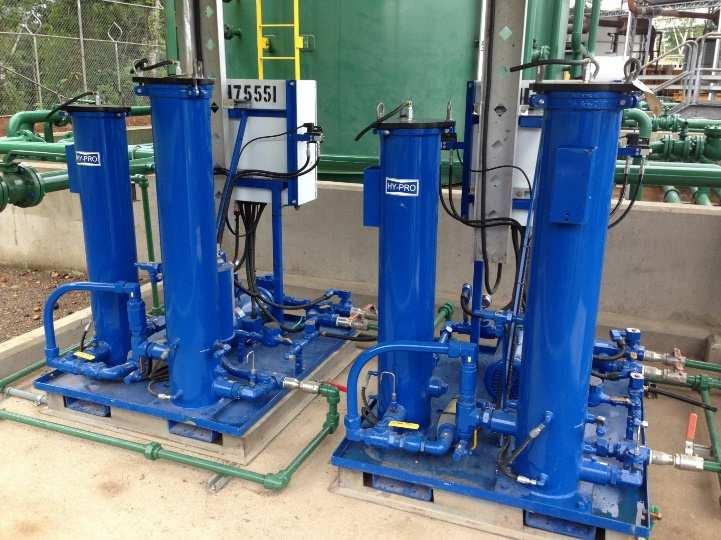
62 HyPro s Vacuum Dehydrator Water Contamination; technologies 4 x HPDEL36 LFM HP107L36-3MB H2O Moisture Sensor 62


63 Fluid Condition Equipment Diesel Filter Housing & Systems: COD COD Diesel Conditioning Filter Systems FSLCOD Diesel Conditioning Filter Systems FCLCOD Diesel Conditioning Filter Carts CSD Diesel Coalesce Filter Housing FCLCOD FSLCOD CSD 63


64 Fluid Condition Equipment VUD V1 Water Removal Equipment : VUD Vac-U-Dry Vacuum Dehydration Systems V1 Compact VUD Vacuum Dehydration Systems COT Turbine Oil Conditioning Systems FCLCOT Turbine Oil Conditioning Filter Carts TMR-N2 Headspace Dehydrator + Nitrogen Generators TMR-Air Headspace Dehydrators COT FCLCOT TMR-N2 TMR-Air 64


![wiping material and is resistant to saturated [light hydrocarbon]](/docs-images/93/112698337/images/65-2.jpg "solvents.")

65 Soft Contaminants - Varnish What is Varnish? A thin, hard, lustrous, oil-insoluble deposit, composed primarily of organic residue, & most readily definable by color intensity. It is not easily removed by wiping with a clean, dry, soft, lint-free wiping material and is resistant to saturated [light hydrocarbon] solvents. Its color may vary, but it usually appears in gray, brown or amber hues. ASTM.D02C.01 definition Varnish can be soft and gooey (Sludge) Varnish can be hard and brittle (Lacquer) Varnish on reservoir ceiling (Stalactites) Varnish deposits on reservoir floor (Plated) 65


66 Soft Contaminants - Varnish Non Aggressive additized oil is mineral based tubine lub and compressor oil. When gas turbines fall casualty to unit trip or failto-start conditions, lube oil varnish is the usual suspect! Varnish deposits on element (GE F6B) Servo valve deposits (stiction) Reservoir deposits Filter element cross section (lacquer) Varnish on load gear (GE F6) 66
 additive and degraded base oil Soft contaminants These soft contaminants are responsible for settling out of the turbine oil and")
67 Soft Contaminants - Varnish What is Varnish? Not simply the oxidation or degradation products. Varnish is: Deposit from depleted AntiOxidant (AO) additive and degraded base oil Soft contaminants These soft contaminants are responsible for settling out of the turbine oil and forming deposits in the system, especially on white metal surfaces and at gear teeth 67

 Pressure Effect on Varnish: Elevated pressure will drive deposits out of solution and 25 o C 25 o C 60 o C increase")
68 Soft Contaminants - Varnish Temperature effect on Varnish: The solubility of varnish is such that they can change from soluble to suspended phase depending upon the temperature of the fluid Varnish contaminants become soluble > 55 C Conversely, the varnish products will fall out of solution over the course of many hours or days when the temperature of the fluid drops below 40 C (for example during outage/shutdown) Pressure Effect on Varnish: Elevated pressure will drive deposits out of solution and 25 o C 25 o C 60 o C increase varnish potential 68
69 Soft Contaminants - Varnish Temperature and Pressure depending Critical Temperature -> 40 0 C 50 0 C Soluble / Insoluble Organic P + White Metal Surfaces 69

70 Soft Contaminants - Varnish Step 1: Lubricant Upset Oxidation Fluid Breakdown Acids + Free radicals 70
 increases")
71 Soft Contaminants - Varnish Step 2: Soluble Impurities Oxidation byproducts build Oil darkens Foul odor Acid Number (AN) increases 71
 Varnish molecules form Looking for")
72 Soft Contaminants - Varnish Step 3: Insoluble Suspensions Saturation point Sugar out of the coffee (soluble to insoluble) Varnish molecules form Looking for partners 72


73 Soft Contaminants - Varnish Step 4: Varnish Deposits Form 73


74 Varnish problems in turbine / compressors Varnish in compressor lube oil causes problems Deposits in heat exchanger High operating temperature Bearing failures Unplanned maintenance & downtime Premature oil disposal Sticky valves Fail Starts Unit Trips Gearbox damage 74
75 More soft contaminants related problems Deposits cause a lot of problems: Sticking valves Plugged lubricant orifices Plugging filters Inefficient heat exchanger operation Bearing Lubrication Loss of Seals 75

76 More soft contaminants related problems Source: Focus Labs, Thailand Source: Smurfit Kappa, Germany 76


77 Fluid Condition Equipment SVR ICB Varnish & Acid Scavenging Systems : SVR Soluble Varnish Removal Filter Systems FSTO Turbine Oil Varnish Removal Systems FSA Phosphate Ester Varnish Removal Systems FSJL Jet Lube Varnish Removal Systems ECR Electrostatic Contamination Removal Systems ICB Ionic Charged Bonding Filter Elements FSTO ECR FSA FSJL 77


78 Fluid Condition Equipment Fluid Handling, Storage & Customer made: LCS LCS Liquid Conditioning Station Custom Equipment Custom Equipment: FSAPE Custom Equipment: V10-ATEX Custom Equipment: V5 Explosion Proof Class 1 Div 1 Custom Equipment: Heater & HighSpeed Flushing unit 78
79 Thanks End of this part of the presentation Next Presentation: Market Approach / Markets 79