Managing Your LEV Systems
|
|
|
- Jessica Dixon
- 5 years ago
- Views:
Transcription


1 Managing Your LEV Systems

2 About the Presenter Chartered Mechanical Engineer; P601 Examination & Testing; P602 Design; Mechanical & Electrical Team Manager at Mabbett. Equally importantly: Practicing LEV Examiner; Practicing LEV designer.
3 Copyright Contains public sector information published by the Health and Safety Executive and licensed under the Open Government Licence. Some images are copyright of TSI Airflow Instruments.
4 Why listen? What does this presentation aim to do? Give you a flavour for the things to look for and actions to take as an LEV owner and operator. What it won t do? Refer in detail to legislation (which is obviously important too!); or Be comprehensive.
5 The Basics - What is an LEV System? Local Exhaust Ventilation - generates a localised air flow to remove airborne contaminants before they enter an operator s breathing zone. LEVs are a form of engineering control. What is not an LEV system? General ventilation. General ventilation in combination with RPE.
6 The Basics - What does an LEV System look like? LEVs come in all shapes and sizes. Very small (e.g. tooling extraction); up to Enormous (e.g. vehicle paint booths). From my experience on larger sites it is common to discover LEV systems during testing and examination.


7 What makes up an LEV system?
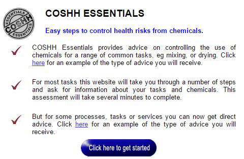
8 When do I need one? 1. COSHH Risk Assessment (Regulation 6 - Suitable and Sufficient Risk Assessment). 2. Use the Hierarchy of Control (Regulation 7) to determine the controls for the risk. Lots of processes will normally have LEV applied - dusty processes, welding, stone cutting, feed mills, etc.
")
9 Hierarchy of Control - Options (Croffles)
10 Why is their management important? Lots of things can go wrong with an LEV system, it can: Be poorly designed and/or commissioned; Deteriorate, often without any obvious indication; Be poorly applied and understood. There is substantial evidence to indicate many existing systems are underperforming.
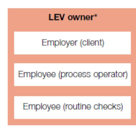
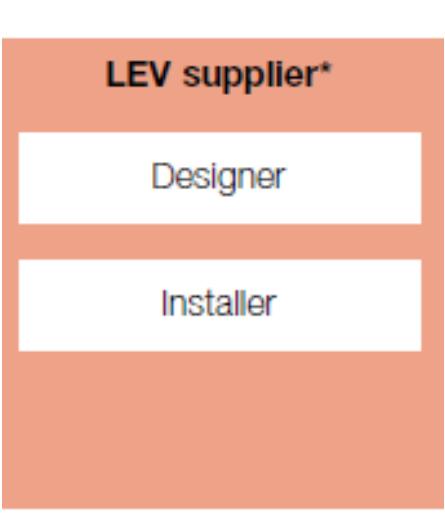

11 Who has responsibility? Roles Can Overlap
12 Thorough Test and Examination Comprises Thorough evaluation of system control, over and above routine checks and maintenance; Report, to be maintained for at least 5 years. Frequency determined by process and/or examiner.
13 Thorough Examination and Testing The Test and Examination has a number of elements but the two most important are Qualitative ( Assess Control Effectiveness ) and Quantitative ( Measure Technical Performance ) evaluation. Both elements have their own specific equipment and best practice approaches.


14 Qualitative Evaluation - to the Naked Eye


15 Qualitative Evaluation - with a Dust Lamp

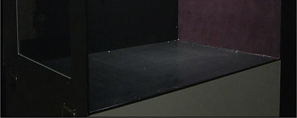
16 Qualitative Evaluation - Smoke
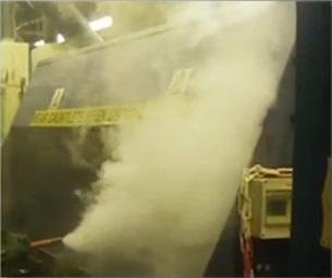

17 Qualitative Evaluation - Smoke Before After
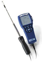

18 Quantitative Evaluation Instruments
19 Quantitative Evaluation Measurements
20 Testing and Examination Other elements: Preparation, review of system documentation; Thorough visual and structural examination. Examiner s duty to warn the client promptly if the system is deemed unsafe.
21 Testing and Examination - Common Misinterpretations A system cannot pass solely because: The measurements were more or less the same as the previous test; Duct velocities were comparable with best practice or even commissioned velocities;.. All aspects of the system performance should be considered.
22 Testing and Examination - How not to Succeed Select your examiner purely on the basis of cost; Admonish your staff for using the LEV system; Make no effort to identify or manage the documentation associated with the system and any alterations; Don t develop any knowledge of the system yourself and don t make your own evaluation of the findings; Don t act upon the recommended actions.
23 LEV User Manual and Logbook User Manual - how the system should be maintained, how it is configured and the risks associated with the system. Logbook - records of checks, maintenance and use. In my experience, these are seldom available.
24 Common Problems (that can be dealt with easily) Operators do not understand the limitations of the hoods; Proximity of hoods to other air movement (e.g. general ventilation diffusers); Clutter and obstruction; Poor maintenance (e.g. fan, filter); Improvements to hood design.
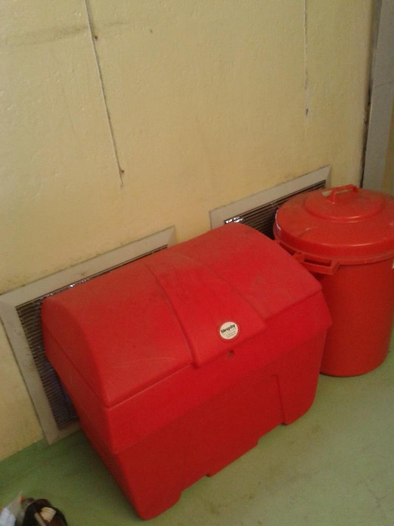
25 Clutter
26 Managing changes to your LEV Systems This could happen when: An existing system is identified as deficient; A new process or machine is introduced; or An existing system needs to be expanded or modified* (e.g. other sources of exposure identified). * Note, this should never happen without the system being recommissioned.

27 Guidance

28 Hood Design - Categories


29 Hood Design


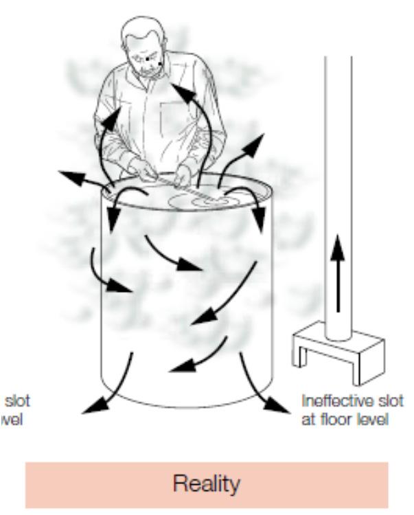
30 Hood Design - Understand the Propagation of Contaminant


31 Hood Design - Understand how the Operators will use the Hood


32 Hood Design - Understand how the Operators will use the Hood

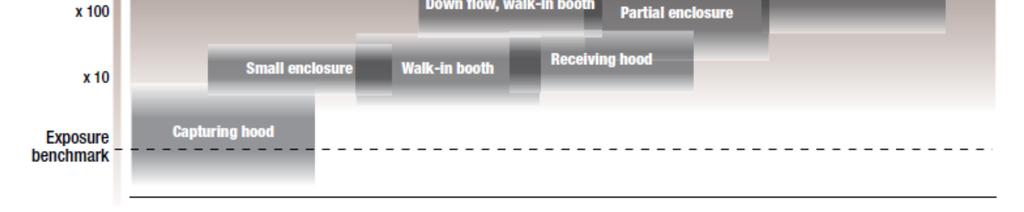
33 Hood Design Benchmarking
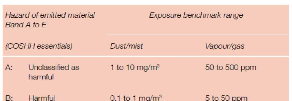
34 Hazard Classification

35 Hood Design
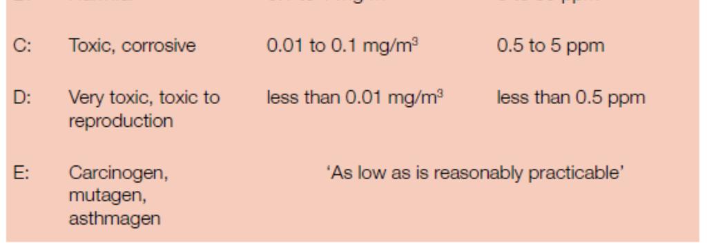
36 Capture Hoods - Capture Velocity
37 Capture Hoods - Capture Velocity Condition of Dispersion of Contaminant Example Capture Velocity, m/s Released with practically no velocity into quiet air Released at low velocity into moderately still air Evaporating from tanks; degreasing, etc to 0.5 Spray booths; intermittent container filling; low speed conveyor transfers; welding; plating; pickling 0.5 to 1.0 Active generation into zone of rapid air motion Spray painting in shallow booths; barrel filling; conveyor loading; crushers 1.0 to 2.5 Release at high initial velocity into zone at very rapid air motion Grinding; abrasive blasting; tumbling 2.5 to 10.2 Lower End of Range 1. Room air currents minimal or favourable for capture 2. Contaminants of low toxicity or of nuisance value only 3. Intermittent, low production 4. Large hood-large air mass in motion Higher End of Range 1. Disturbing room air currents 2. Contaminants of high toxicity 3. High production, heavy use 4. Small hood-local control only Note: Capture velocity is not the same as face velocity.

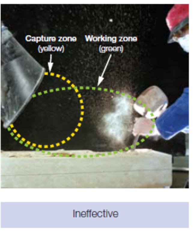
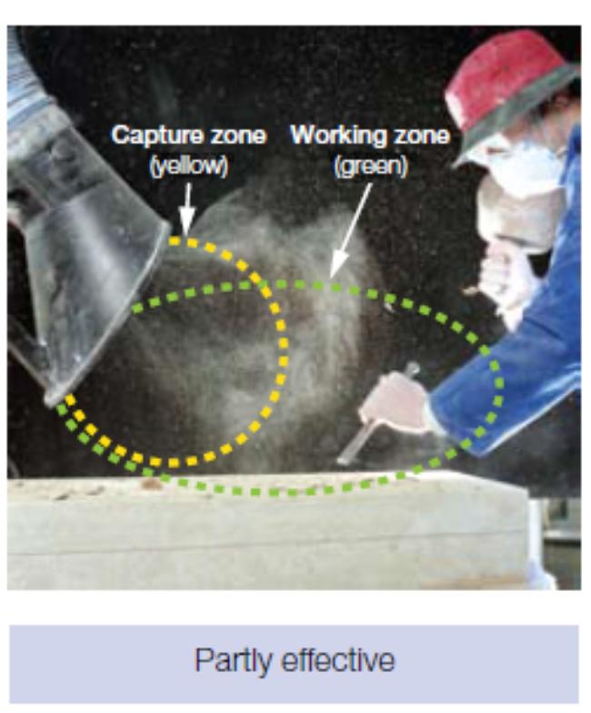
38 Capture Hoods - Operation

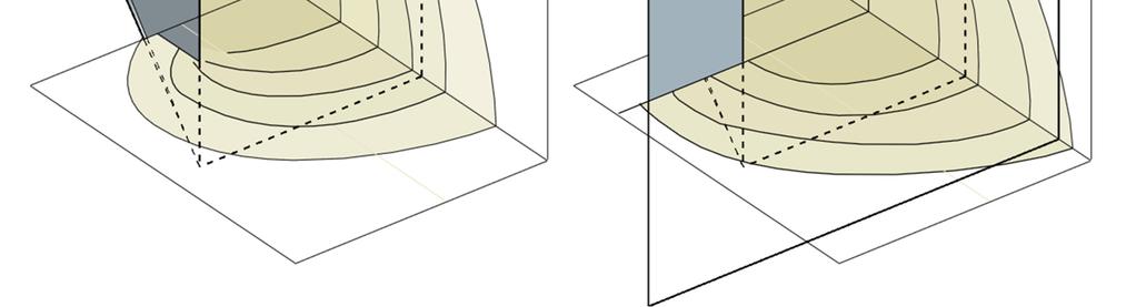
39 Capture Hood - Flanges

40 Hood Design - Local Flow Indicators

41 Hood Design - Local Flow Indicators
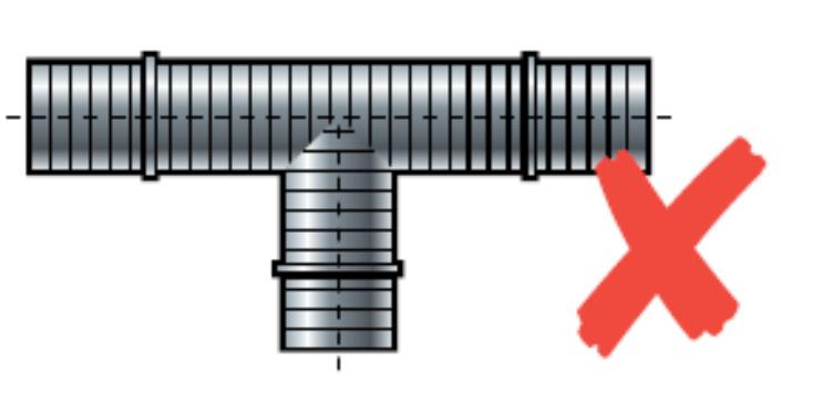
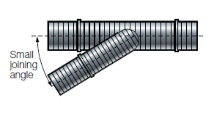
42 Duct System Design Design for recommended transport velocities or better; Keep duct pressures negative in building; Use smooth bore duct; Avoid sharp transition pieces; Allow access for cleaning, testing and inspection; and Minimise flexible duct.

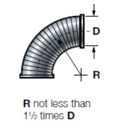
43 Duct System Design

44 Duct Design - Flexible Duct

45 Duct Design - Transport Velocity
46 Duct Design - Transport Velocity Nature of Contaminant Examples Design Velocity Vapours, gases, smoke All vapours, gases, smoke Any economic Fumes Welding 10.2 to 12.7 m/s Very fine light dust Cotton lint, wood flour, litho powder 12.7 to 15.2 m/s Dry dusts and powders Fine rubber dust, Bakelite moulding powder dust, 15.2 to 20.3 m/s jute lint, cotton dust, shavings (light), soap dust, leather shavings Average industrial dust Grinding dust, buffing lint (dry), wool jute dust 17.8 to 20.3 m/s (shaker waste), coffee beans, shoe dust, granite dust, silica flour, general material handling, brick cutting, clay dust, foundry (general), limestone dust, packaging and weighing asbestos dust in textile industries Heavy dusts Sawdust (heavy and wet), metal turnings, foundry 20.3 to 22.9 m/s tumbling barrels and shake out, sand blast dust, wood blocks, hog waste, brass turnings, cast iron boring dust, lead dust Heavy or moist Lead dusts with small chips, moist cement dust, >22.9 m/s asbestos chunks from transite pipe cutting machines, buffing lint (sticky), quick lime dust


47 Stack Design

48 Stack Design

49 Stack Design

50 No Stack Design

51