3 PROJECT DESCRIPTION
|
|
|
- Brian Nash
- 5 years ago
- Views:
Transcription
1 3 PROJECT DESCRIPTION EGP has proposed the development of a 40MW solar photovoltaic (PV) power plant to supply power to the Gold Field South Deep Gold Mine. Photovoltaic Solar Panel technology is being proposed which will occupy up to a maximum of 130 ha (1.2 km 2 ) for the 40MW Solar PV Plant. This chapter provides a detailed description of the proposed Project. 3.1 PROJECT OVERVIEW Project Background The Photovoltaic Process Solar energy systems produce energy by converting solar radiation into electricity or heat using solar panels. The proposed project will use PV solar technology to generate electricity. The system will be made up of subfields. The PV solar technology chosen for this project consists of the following main components: Photovoltaic (PV) cell: The PV cell is the device that traps and converts the thermal energy from the sun into electricity. The absorbed solar energy excites the electrons inside the PV cell and produces electrical energy. The PV cells are usually built with polycrystalline silicon and produce Direct Current (DC). Polycrystalline (multiple silicon crystals) solar cells will be used for this Project. PV module and panel: The PV module is the set of interconnected photovoltaic cells. In the case of crystalline silicon cells, after tests and screening to match the current and the voltage, the cells are interconnected and encapsulated between a transparent front (usually glass) and a support material. The PV module is mounted on an aluminium structure and on a tracker system (Figure 3.1) to track the sun and optimise the capture of energy from the sun. Photovoltaic panels include one or more PV modules mounted as a unit; PV array: The PV array is the integrated assembly of modules together with support structures to form a DC energy production unit; Inverter: The supply of electric energy to the grid requires the transformation of PV array DC current into alternating current (AC) by means of an inverter; Transformer: The AC current is stepped up to the grid voltage by means of transformers; and 3-1

2 Substation: Substations typically transform voltage from high to low, or the reverse. A substation may include transformers to change voltage levels between high transmission voltages and lower distribution voltages, or at the interconnection of two different transmission voltages. Figure 3.1 Illustration of a single axis tracking solar PV unit. Image source: 3-2

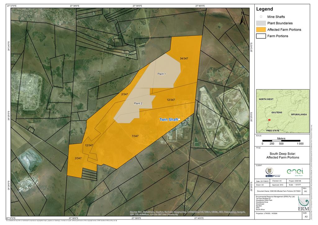
3 Figure 3.2 Aerial View of PV Solar Farm Source: Barry Wiesner Project Location and Land Ownership The Project is to be developed on a green field site owned by Gold Fields South Africa located on the Gold Field South Deep Gold Mine property near the town of Westonaria in the Gauteng Province. The nearest major city is that of Johannesburg with the nearest major airport being OR Tambo and the nearest major port being Durban harbour. The project site is located at an altitude of approximately 1620masl. The proposed site is located approximately 50 kilometres south-west of Johannesburg, South Africa. The GPS coordinates for the centre of the site are 26 24'36.00" South 27 39'16.00" East. The site is located within these farm portions: Portion 34 of the Farm Doornpoort 347; Portion 7 of the Farm Doornpoort 347; Portion 12 (a Portion of Portion 7) of the Farm Doornpoort 347; and Remaining Extent of Portion 2 of the Farm Doornpoort 347. The site is located adjacent to existing mining operations. The site has not been used for mining activities or development. With reference to Figure 3.4, the corner points of the proposed power plant boundary and the 11kV underground transmission line are listed in Table 3.1 and Table 3.2 below. The properties and relevant ownership details on which the proposed site is located are listed in Table
4 Table 3.1 Co-ordinates of the corner points of the proposed power plant boundary. Label Longitude Latitude A 27 38' " E 26 25' " S B 27 38' " E 26 25' " S C 27 38' " E 26 25' " S D 27 39' " E 26 25' " S E 27 38' " E 26 25' " S F 27 39' " E 26 24' " S G 27 39' " E 26 24' " S H 27 39' " E 26 24' " S I 27 39' " E 26 24' " S J 27 39' " E 26 24' " S K 27 39' " E 26 24' " S L 27 39' " E 26 24' " S M 27 39' " E 26 24' " S N 27 39' " E 26 24' " S O 27 39' " E 26 24' " S P 27 39' " E 26 24' " S Q 27 39' " E 26 24' " S R 27 39' " E 26 24' " S Table 3.2 Coordinates of the 11kV underground transmission line Point Latitude Longitude Start ' 35.05" 27 39' 22.36" End ' 35.01" 27 39' 36.09" Table 3.3 Land ownership associated with the project site Farm Name Doornpoort 347 IQ Doornpoort 347 IQ Doornpoort 347 IQ Doornpoort 347 IQ Portion No. 21 Digit SG Code Owner Title Deed Gold T0IQ Fields Operations Ltd GFI Joint T0IQ Venture Holdings Pty Ltd Gold T0IQ Fields Operations Ltd GFI Joint T0IQ Venture Holdings Pty Ltd Registration Date T104921/ /09/1998 T56763/ /05/1999 T104921/ /09/1998 T567765/ /05/

5 Figure 3.3 Regional location of the proposed project Figure 3.4 Location of the Preferred Site Alternative 3-5
6 3-6

7 Figure 3.5 Corner points of the Project Boundary 3-7
8 3.2 PROJECT AREA OF INFLUENCE For the purposes of this impact assessment, the definition of the Area of Influence (AoI) encompasses: The area likely to be affected by: (i) the project and the client s activities and facilities that are directly owned, operated or managed (including by contractors) and that are a component of the project; (ii) impacts from unplanned but predictable developments caused by the project that may occur later or at a different location; or (iii) indirect project impacts on biodiversity or on ecosystem services upon which Affected Communities livelihoods are dependent. Associated facilities are facilities that would not have been constructed or expanded if the project did not exist and without which the project would not be viable. Cumulative impacts that result from the incremental impact, on areas or resources used or directly impacted by the project, from other existing, planned or reasonably defined developments at the time the risks and impacts identification process is conducted. The Project Area of Influence is sub-divided into two main categories, namely, the Socio-economic AOI and the Biophysical AOI. These are discussed in the sections below Socio-economic AOI Socio-economic Area of Direct Influence The Area of Direct Influence, ADI, includes the Project footprint and related facilities as well as the associated effects of the Project on the receiving environment. This encompasses: The 1.6 km 2 Solar PV site; and The 11kV line to the Mine s grid. In the context of this study, the ADI further includes areas around the site likely to be affected by the Project activities during the pre-construction, construction and operation phases. The effects can be positive or negative, short or long term or permanent, as well as direct and in-direct. These areas include the settlements located within close proximity to the Project Site. Based on the nature and scale of this Project, the ADI will be old Westonaria Local Municipality, and encompasses the following areas (refer to Figure 4.1): Westonaria and Hillshaven; Glenharvie and Venterspost; Bekkersdal and Simunye; 3-8
9 Jachtfontein Kalbaasfonteian Zuurbekom; and Thusanang. The Area of Direct Influence is referred to collectively as Westonaria in this baseline. Socio-economic Area of Indirect Influence The Socio-economic Area of Indirect Influence, AII, includes areas within a wider radius of the Project Site, which may be affected by the Project, this includes, although to a lesser extent, the remainder of the Rand West City Local Municipality and the West Rand District Municipality Biophysical Area of Influence The biophysical Area of Influence was developed based on inputs from the various specialists studies. For the construction phase and the operational phase an Area of Direct Influence (ADI) and an Area of Indirect Influence (AII) was considered. The rational for this is outlined in Table 3.4 below and illustrated in spatial terms in Figure 3.7. Table 3.4 Rational for the development of the biophysical Area of Influence (AOI) Component Construction Phase Operational Phase ADI AII ADI AII Surface Water & Wetlands Site only. Alteration of Surface run-off None. Terrestrial Biodiversity Soils, Land Use and Land Capability Noise Air Site only. Loss of grassland habitat. Site only. Loss of grazing land; Soil exposure to potential wind and water erosion. Site only. Noise from construction activities. 250m from the site. Windblown dust 500m from the site. Potential loss of surface run-off; Potential increase sediment load into the water course. Neighbouring farms / grassland within 1km. Potential disturbance of birds and mammals; habitat fragmentation. Impacts on surface water run-off will be limited to the project site only None, impacts have taken place during the construction phase. None None None None None None Same as ADI. None None None, impacts have taken place during the construction phase. 3-9
10 Component Construction Phase Operational Phase ADI AII ADI AII due to exposed soils. Cultural Heritage Site only None None None Visual Based on view shed model. Based on view shed model. Based on view shed model. Based on view shed model. 3-10

11 Figure 3.6 Socio-economic AOI 3-11
on")
12 Figure 3.7 Project Area Of Influence (AOI)on Biophysical receptors 3-12
13 3.3 PROJECT COMPONENTS The key project components considered in this EIA are as follows (See Annex D for the Layout drawing): Fencing; Solar PV Panels; 11kV transmission line; Internal cabling; Inverters and transformers; Delivery cabins; Road (internal & access); Project build infrastructure (temporary admin offices, security house, workshop areas and stores); Construction Laydown Area/s; Temporary site camp area; Ancillaries; and Operations and Maintenance (O&M) building A concrete batching plant may be required; however, this is still under investigation. The abovementioned project components are discussed in detail in the sections below. Solar PV power plant configurations The PV plant is split in two separate 20MW areas each one has the characteristics as described in Table 3.5 Table 3.5 Solar PV power plant characteristics Item Description Operations and Maintenance 150m 2 Construction temporary laydown area 10.8ha Solar plant footing 130ha PV Technology (module, panel, cell, array) The PV modules are c-si (Multicrystalline Silicon) which will be mounted on a single axis tracker. Central inverters with unit transformers will be used and the voltage level is 1500V. The panels will be mounted in a northern direction on a 0 0 angle however the tracking angle will be Error! Reference source not found. illustrates the PV panel datasheet, and Figure 3.8 shows a typical PV Solar Farm. 3-13


14 Figure 3.8 Typical PV Arrays Figure 3.9 Typical Inverter Enclosures on site 3-14

15 Figure 3.10 Typical Power Transformer 3-15

16 Figure 3.11 Solar PV plant functional layout 3-16
17 3.3.2 Access routes and roads As the proposed project site is situated alongside the R28, a district arterial road, no additional roads or road upgrades will be required. Most of the equipment for the project will come from the Johannesburg area and thus the main road that will be utilised are as follows: N1; N12 (R501); and R28 (Randfontein Road). Traffic There will be an increase in traffic during the construction phase for the delivery of the solar panels, materials, machinery and labour. Equipment to the site will be transported on the N1, N12 and R 28 roads. No new external tracks will be established and only existing roads will be used. New internal roads will be established to access the PV Site. Vehicle movements anticipated during peak construction periods is estimated to be between 1-50 people throughout the project, with the numbers very high at peak (between month 7 and 10). Approximately 25 Light Duty Vehicles (LDVs) are expected on average throughout the lifespan of the project. An additional 3 buses and 8 mini buses are anticipated throughout the lifespan of the project, where the number is expected to decrease at the end of the project. The traffic will diminish post construction and there will be only a small number of vehicles travelling to and from the site during operations for maintenance purposes. Where appropriate, EGP will develop traffic management measures to control construction and operational traffic Admin /Office Building The Operations and Maintenance (O&M) buildings shall consist of the following facilities: Kitchen; Restrooms with at least one dedicated women s restroom; Waste storage area including oil containment; Warehouse; Meeting room; Offices; SCADA /Control room; Control room and LV Electrical room; and Parking lot. These facilities shall be located in one or more modules within a single building lying on one floor. 3-17
18 3.3.4 Services Waste The waste storage area shall be located outside of the solar PV power plant O&M buildings allowing enough space for a truck to manoeuvre and access the area. The waste storage area shall have rain/snow and solar radiation protection and shall be designed to ensure proper ventilation with artificial illumination and possibilities of locking. The waste storage area shall be equipped with waste containers/barrels trays for consumables collection and shall be divided in different compartments to separate lubricant oils, greases, solvents, ordinary waste as per local legislation and international standards. This area shall contain oil spill pallets. Sewage Sewage storage tanks will be used during the construction phase as a means to temporarily store sewage accumulated at the facility. These tanks will be serviced frequently by a registered company and disposed of appropriately at a licenced waste facility. Water Supply It is anticipated that water will be sourced from one, or a combination, of the following sources: (a) (b) Licensed borehole water on site; or Existing licensed water-pipe on site. Storm Water Management Structures If required, storm water control measures will include the use of shade netting barriers (or similar) or geo-fabric barriers in areas susceptible to erosion. These storm water control measures are usually placed directly across the path of flow of storm water. Poles and logs, staked in along the contours of a slope susceptible to erosion may also be used Electrical connection to the Mine The power generated at the solar PV plant will be connected to the Gold Fields South Deep Gold Mine 11kV emergency power supply line which is located approximately 250m east of the solar plant. Refer to Figure 3.11 and see Annex D of this Report. 3-18
19 The delivery point for the Project is South Deep Gold Mine existing 11kV distribution emergency power line which is located approximately 500metres from the Project site. The delivery point including the facility metering is located at the terminating equipment of the 11 kv loop-ins loop-outs on each side of the 11 kv emergency line. The Project will be connected on an existing 11 kv emergency line between Twin Shaft and South Shaft. Each 20MW supply will be able to be isolated and the bus section of the 11kV emergency line will be able to be closed to connect the two shafts during emergency conditions. EGP will construct the loop-ins loop-outs and then transfer ownership of the interconnection facilities to the South Deep Gold Mine. 3.4 PROJECT IMPLEMENTATION Construction Phase Construction Activities The construction phase is anticipated to start in the second quarter of 2018 over a period of 10 to 12 months. The following activities will be undertaken during the construction phase of the project: Detailed land surveys and markings; Establishment of access roads; Site preparation/clearing; Establishment of laydown areas on site; Transport of component or equipment to site; Erection of the panels; Establishment of ancillary structures; Connection of the substation to 11kV line; and Undertake rehabilitation of disturbed areas. The following temporary facilities will be constructed for the duration of the construction phase: Workshop and maintenance area; Stores (for storing and handling fuel, lubricants, solvents, paints and construction material); Contractor lay-down areas; Mobile site offices; Temporary waste collection and storage area; and Parking area for cars and equipment. Construction Schedule Construction activities are anticipated to start in Q2of 2018, and will continue over a twelve (12) month period. 3-19
20 Water requirements The preliminary water requirements for the solar PV power plant have been approximated to be 500,000 litres (500m 3 ) per month during the construction phase, for the following uses batching (if necessary), drinking, sanitary facilities, access track construction, dust control, and fire-fighting reserve. Waste Generation Construction wastes will comprise general domestic waste including sanitary and food waste, office waste, organic material, small volumes of wastes arising from mobile plant, chiefly waste lubricating oil and packing materials (e.g. crates). Employment Employment during the construction phase will consist of 125 local full time equivalent (FTE) jobs during the 10 month construction period Operational Phase Operational Activities The solar PV power plant will be operated on a 24 hour, 7 days a week basis. The solar PV panels have an estimated product life of 25 years, following which EGP and Gold Fields can negotiate to either extend the life of the project to the LoM or to decommission the project. Operational activities will include: Cleaning of the modules by trained personnel using a high pressure water hose; Vegetation management for under and around the modules to allow maintenance and operation at full capacity; Maintenance of all components including modules, mounting structures, trackers, inverters, transformers switching station plant and equipment; Control room management and maintenance of the sanitation facilities; Supervision of the electricity production; and Site security monitoring. 3-20
21 Water Requirements During the operational phase water will be required for two main activities, namely panel cleaning and human consumption, this are further described below: Water consumption during the operational phase: Panel cleaning per annum Domestic Use = L/annum = L / annum Waste Generation Operational phase waste streams are as follows: General domestic waste including sanitary and food waste; and Office waste, and organic material. The disposal of waste will be carried out in accordance with the relevant legislation. All solid wastes generated will be disposed of at licensed landfill sites, for general and/ or hazardous waste streams. No waste material will remain on site. Employment During the operational phase approximately 25 local jobs will be created. 3-21