Simulating large scale combustion systems
|
|
|
- Gervase Dennis
- 5 years ago
- Views:
Transcription
1 STAR Global Conference 2016 Simulating large scale combustion systems Wian van der Merwe Warwick Ham South Africa
2 Agenda Introduction. Holistic analysis approach. Plant schematics. Coal mill and classifier. Dust distribution boxes. Windbox and burners. Project progress. Conclusions. Q&A.
3 Introduction Purpose of investigation: Present a detailed investigation of the internal flow, thermal, particulate, and combustion characteristics of a large scale fossil fuel fired boiler system in South Africa, under different coal qualities and operating conditions. Establish a modelling foundation for future maintenance and design optimisation. Integrated thermal and CFD model of a large coal combustion system, broken down into various sub-components. Thermal, mass and energy balance model based on actual operating data. Detailed CFD sub-models of various components. Integrated approach needed to address real-world problems such as: Raw Coal quality outside the design envelope. Operating performance decline which reduces overall capacity. High velocities and ash load high causing increased erosion and reduced availability. Maintenance costs increasing steadily.
4 Introduction Steady decline in coal quality: Coal quality outside the design envelope. Moisture in coal increased by 24%. Ash in coal increased by 11%. Calorific value decreased 13%. Washed coal contains high proportion of fine matter. Particle size distribution outside limits. Increase in maintenance costs. Decrease in mill availability from 98.3% to 96.9%.
5 Holistic analysis approach Very large system comprising of different complex multi-physics sub-components. Broken down into pre-determined sub-components. Save on complexity and computational time. Each sub-system has specific outcomes. STAR-CCM+ allows for simulation of each sub-system within one domain. Sub-components: 1. Coal mill and classifier modelling. 2. Characterisation of dust distribution boxes. 3. Windbox and burner flow distribution analysis. 4. Furnace combustion modelling including DTF. 5. Boiler flue gas flow and fly ash erosion modelling. 6. Air heater characterisation. DTF Drop Tube Furnace.


6 Plant schematic 3. Windbox. 5. Boiler flow and fly ash. 2. Dust distribution box. 1. Coal mill and classifier. 6. Tubular air heater. 3. Burners. 4. Coal combustion.


7 Overall plant CAD used for CFD
8 Coal mill and classifier Modelling approach MPS-180 mill and classifier. Vertical spindle mill with stationary throat, rotating table and three grinding rollers. Adjustable classifier vanes. 4 Mills per unit required for full load operation. Outcomes: 2 phase flow behavior, particularly through throat and classifier. Classifier effectiveness. Modelling approach: Rotating components modelled using wall relative rotation rates on component boundaries. Energy extracted from hot (PA) flow after throat based on energy balance calculations. Mass of evaporated coal moisture added as a multicomponent gas. RSM (linear pressure strain) turbulence model. A fixed distribution of Lagrangian particles from µm was injected at each load. Realistic load extremely computationally intensive. One way coupling (low volume load, less computationally intensive) total particles resulted in track files of ~40GB. PA Primary Air.

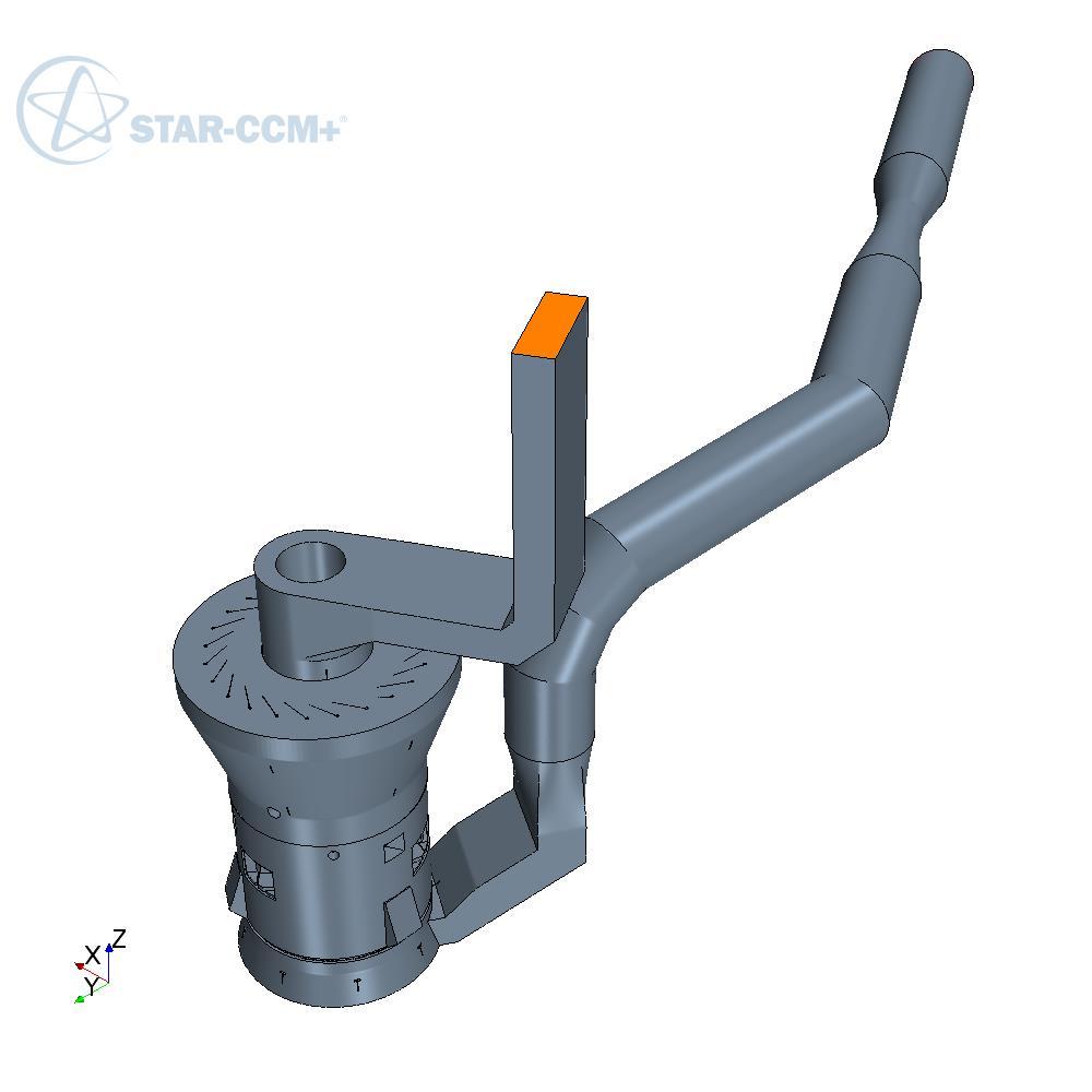
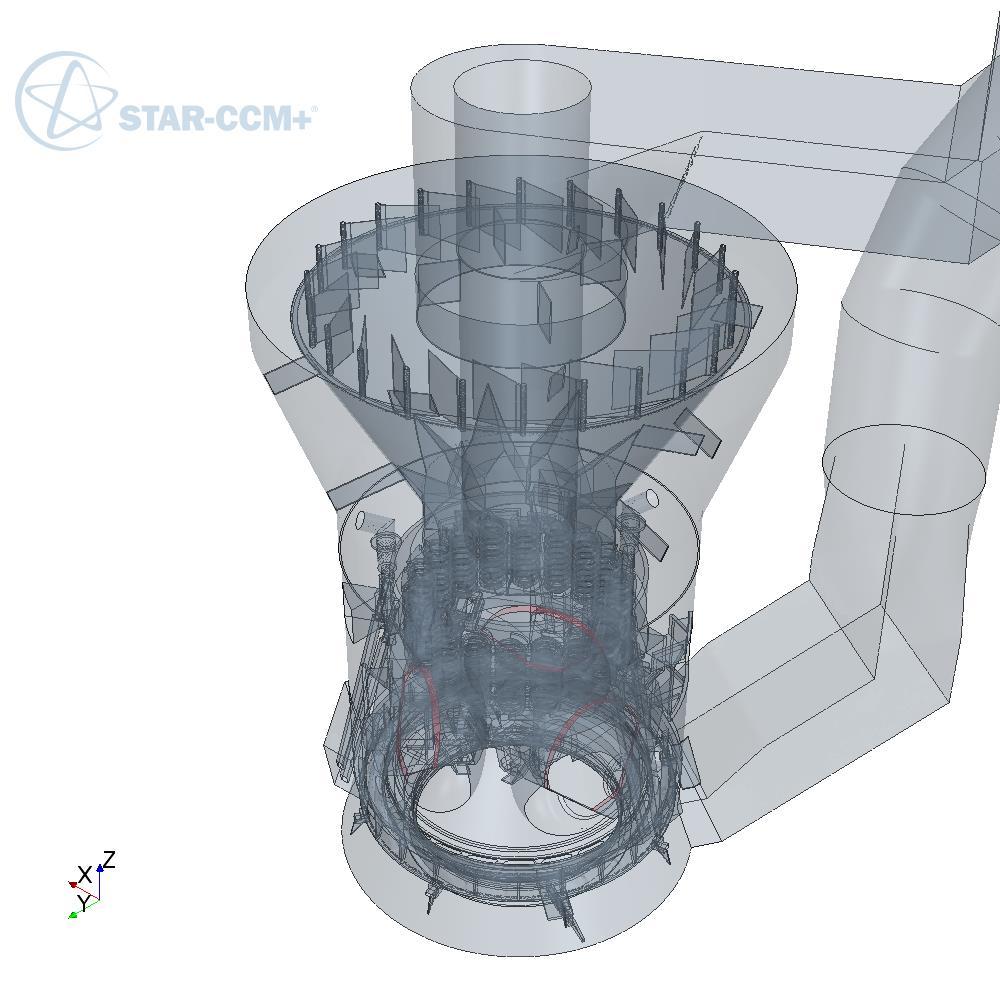
9 Coal mill and classifier Geometry

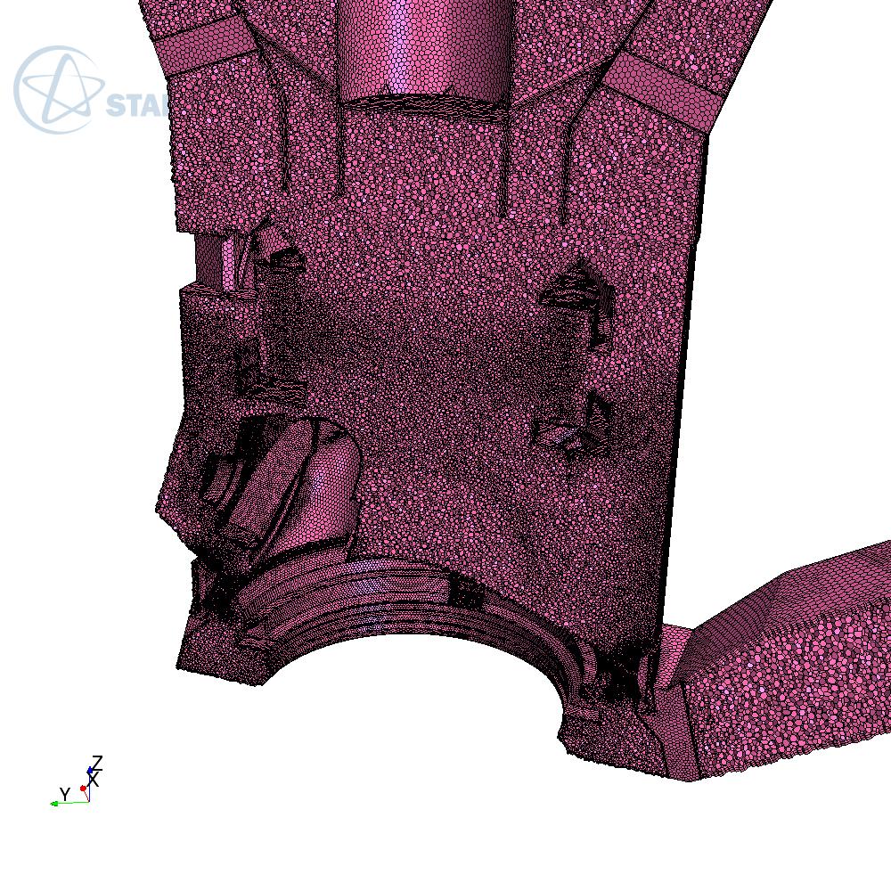
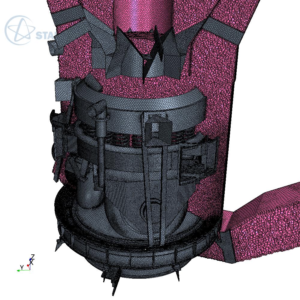
10 Coal mill and classifier Numerical mesh 9+ million cells.


11 Coal mill and classifier Results Velocity magnitude. Velocity magnitude halfway through throat.


12 Coal mill and classifier Results Cell relative velocity. Iso-surface of velocity.


13 Coal mill and classifier Results Velocity magnitude. Velocity magnitude.

14 Coal mill and classifier Results Mill_01_B

15 Coal mill and classifier Results Velocity magnitude: Small vane angle. Velocity magnitude: Large vane angle.
16 Coal mill and classifier Results


17 Coal mill and classifier Results Erosion rate prediction. Real world erosion.
18 Dust distribution boxes Modelling approach Distribution (Splitter) boxes: Distributes PF from 1 mill to 4 pipes, each leading to a burner. Two unique distribution boxes per unit. Outcomes: Quantify effectiveness of boxes to distribute PF evenly. Predict a realistic pressure drop. Modelling approach: Distribution profiles entering splitter boxes mapped from mill model. Eulerian multiphase used to capture realistic PF load. 5 Particulate dispersed phases used to model five particle sizes from µm. Particle sizes and flowrates obtained from actual PF samples. Steady state simulation with strong under-relaxation. PF Pulverised Fuel.
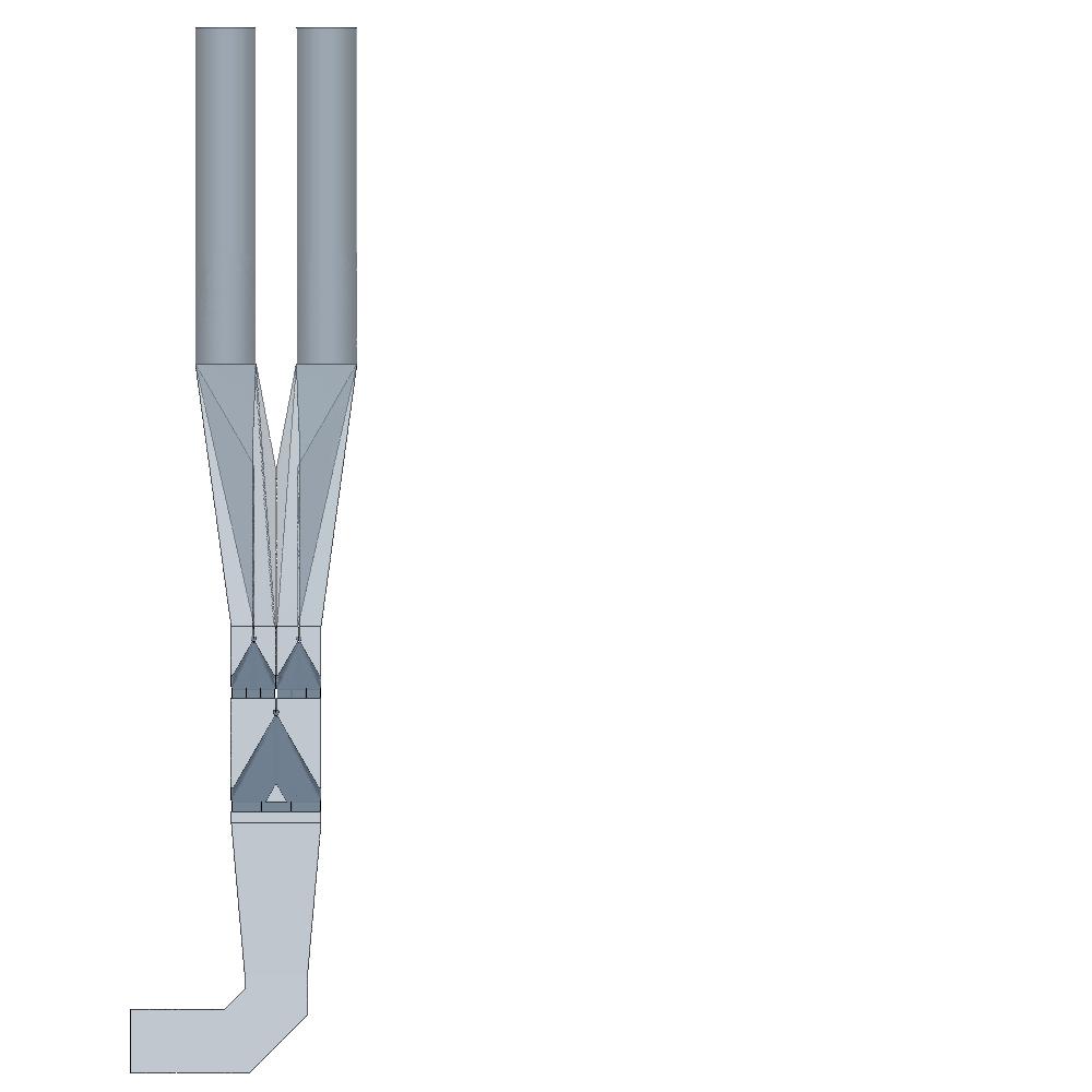
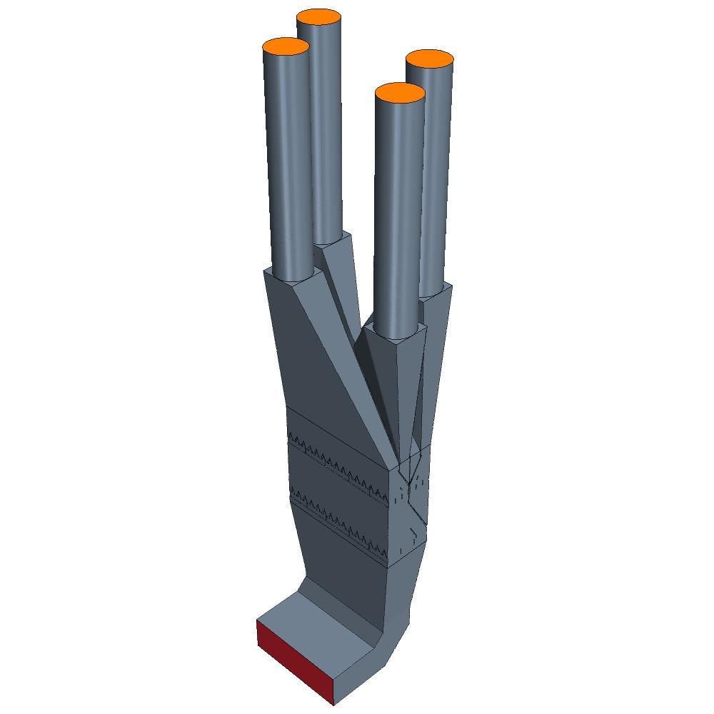
19 Dust distribution boxes Geometry
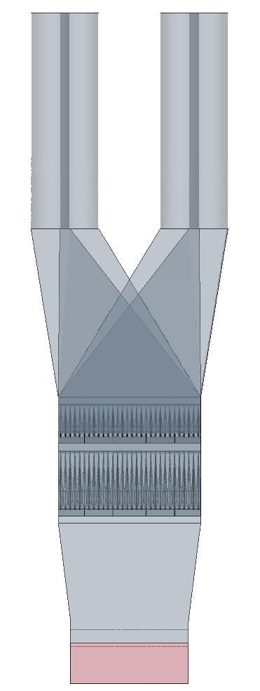
20 Dust distribution boxes Numerical mesh 3+ million cells.


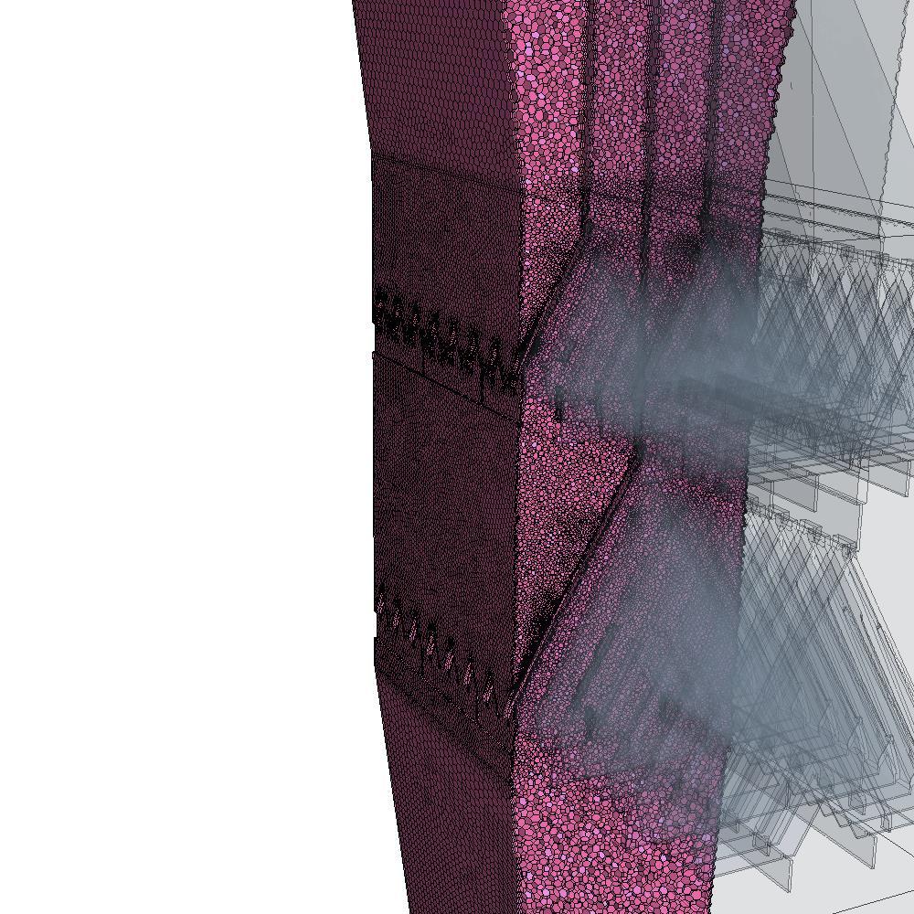
21 Dust distribution boxes Results Volume fraction of 50 µm particles.
![Dust distribution boxes Results Mass flow [kg/s] VF of 50 µm particles at outlets. Outlet 2. Outlet 1.](/docs-images/93/113287518/images/22-4.jpg "1,2 1,0 Mass flow distribution of 50 µm particles Average Avg. - SD Avg. + SD 0,8 0,6 0,4 Outlet 3. 0,2 Outlet 4.")
22 Dust distribution boxes Results Mass flow [kg/s] VF of 50 µm particles at outlets. Outlet 2. Outlet 1. 1,2 1,0 Mass flow distribution of 50 µm particles Average Avg. - SD Avg. + SD 0,8 0,6 0,4 Outlet 3. 0,2 Outlet 4. 0,0 Outlet 1 Outlet 2 Outlet 3 Outlet 4
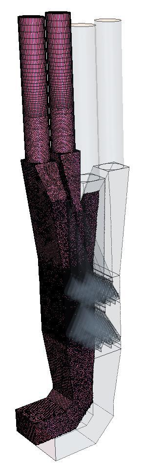
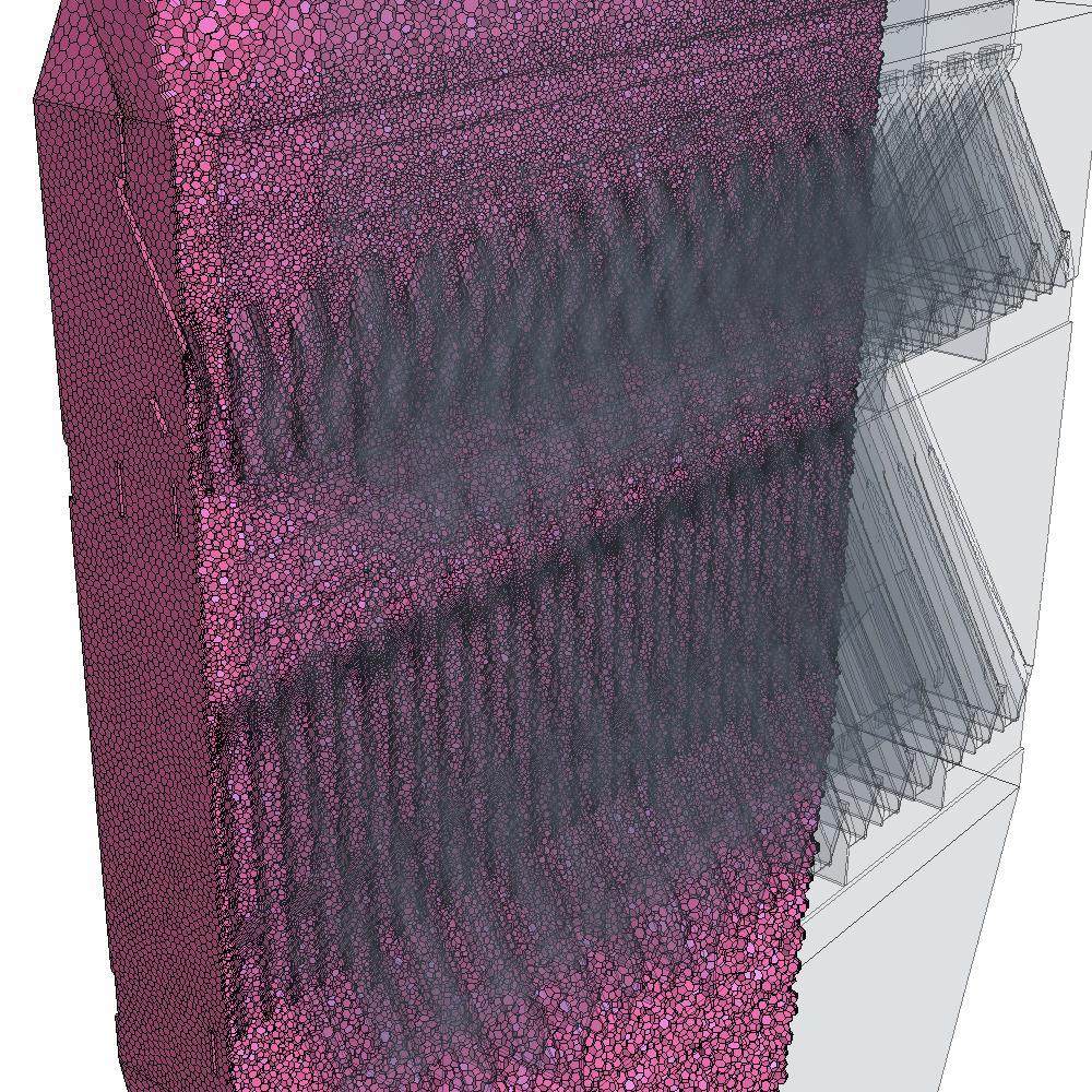
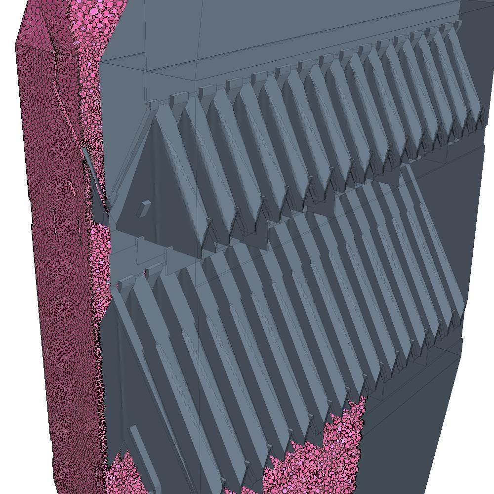
23 Windbox and burners Modelling approach Windbox and burners: Total of 16 burners. 8 Common windboxes, 1 pair of burners in each left and right windbox. Each horizontal row of 4 burners supplied from each mill. Outcomes: Determine the secondary air distribution to each windbox leg. Compare each burner s flow distribution regarding secondary air and core air. PA and PF distribution to burners results from the dust distribution box model. Modelling approach: With flow distributions the priority outcome, only flow was considered in this model. Air heater temperature distribution assumed even until air heater model is completed. PF particles and combustion not included. Very high level of geometric detail. PA Primary Air. PF Pulverised Fuel.


24 Windbox and burners Geometry


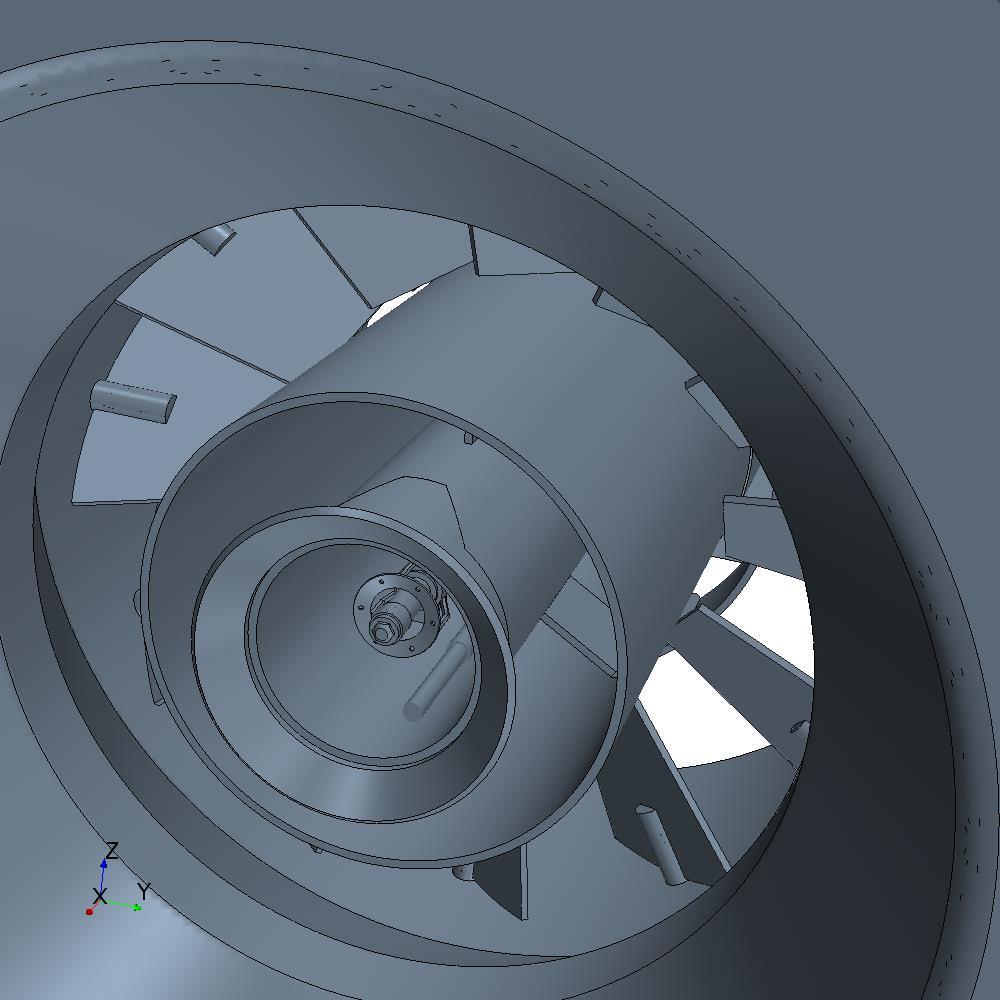
25 Windbox and burners Geometry


26 Windbox and burners Numerical mesh 34+ million cells.


27 Windbox and burners Results Pressure. Velocity in axial direction of burners.
28 13-Aug Oct Dec Mar Apr Apr Jan Mar Jun-15 Project program BBS MPS 180 Mills CFD Report Boiler Combustion CFD PF Piping & Distribution Windbox & Burners DTF Furnace Air Heater Erosion Report QUOTE CONTRACT START PLANNED ACTUAL CONTRACT END
29 Current & future work Windbox and burner characterization: Analyse effects of different load conditions and swirl damper positions on burner flow rate distributions and velocity profiles. (4 simulations of 12 still to be run) Furnace combustion modelling: Calibration of coal burnout rates using DTF rate data. Map data from windbox and burner models onto furnace model to save on computational time. Temperature, velocity and two phase particle transport included in furnace model. Particle combustion rate based on DTF behavior and particle incident radiation HT. Particle size decreases based on combustion rate. Total heat transfer in furnace taken from bulk thermal model. Use coal combustion models to predict burner flame stability, furnace temperatures, and burn out rates. DTF Drop Tube Furnace. HT Heat Transfer.
30 Current & future work Boiler flow and fly ash erosion. Predict areas with high erosion rates due to fly ash. Distribution profiles entering boiler mapped from furnace combustion model. Tube banks modelled explicitly as octagons. Lagrangian particulate phase injected for erosion rate predictions. One way coupling to save on computational time. One burst of particles with a representative Rosin-Rammler ash particle size distribution. Erosion rate based on particle size, density, hardness, shape factor, velocity, and angle of impact with tube surface.
31 Current & future work Tubular air heater: Thermo-hydraulic design review of the existing design. Both flue gas and clean air systems will be modelled together. Tube banks modelled explicitly as octagons. Flue gas distribution profiles entering the air heater mapped from boiler erosion model. Heat transfer from bulk thermal model. Future work will include practical modifications of the existing system to improve operating performance and maintenance issues.
32 Conclusions Detailed investigation of the characteristics of a large scale fossil fuel fired boiler system under different coal qualities and operating conditions. Establish a modelling foundation for future design optimisation. Integrated thermal and CFD model of a large coal combustion system, broken down into various sub-components. Address real-world problems such as: Raw Coal quality outside the design envelope. Operating performance decline which reduces overall capacity. High velocities and ash load high causing increased erosion and reduced availability. Maintenance costs increasing steadily. Coal mill and classifier models already used to develop and determine the effectiveness of design optimisations. STAR-CCM+ allows for simulation of each sub-system within one domain.

33 Thank you.