AŞAĞI ÖVEÇLER MAHALLESİ LİZBON CADDESİ NO:43/4 ÇANKAYA ANKARA ETAB ENERGY
|
|
|
- Cynthia Short
- 5 years ago
- Views:
Transcription
1 1 AŞAĞI ÖVEÇLER MAHALLESİ LİZBON CADDESİ NO:43/4 ÇANKAYA ANKARA

2 2 FERMANTATION UNIT FLOW CHART
3 3 ESTABLISHED FACILITIES: Electric production from landfill(landfill Gas Collecting System) Sorting plant installation(sorting plant) Fermantation plant installation (household, agricultural, cows and poltury waste). Gas holder installation. H 2 S removal unit. Booster Unit and Flare ( gas vacuum and pressure unit ) Biogas Power Plant from landfil and other wastes.
4 4 ELECTRIC PRODUCTION FROM LANDFILL WHAT IS THE LANDFILL GAS? Landfill gas (LFG) is a natural by product of the decomposition of organic material in landfills. ~ (50-60) % methane gas (CH4) ~ (40-50) carbon dioxide (CO2) < % 1 small amount of non-methane organic compounds. Methane is a potent greenhouse gas 28 to 36 times more effective than CO 2 at trapping heat in the atmosphere over a 100-year period. Landfill gas can be recovered and utilized to generate electricity, fuel industries and heat buildings. There are two major benefits to recovering and utilizing landfill gas. The first is that capturing and combusting landfill gas prevents substances like methane from escaping to the atmosphere; the second is that using the energy from landfill gas can replace the use of non-renewable sources of energy such as coal, oil, or natural gas.
5 5 What is the benefits Collecting and Treating Landfill Gas Instead of escaping into the air, LFG can be captured, converted, and used as a renewable energy resource. Using LFG helps to reduce odors and other hazards associated with LFG emissions, and prevents methane from migrating into the atmosphere and contributing to local smog and global climate change. In addition, LFG energy projects generate revenue and create jobs in the community and beyond.

6 6 Flowchart of a Basic LFG Collection and Processing System LFG is extracted from landfills using a series of wells and a blower/flare (or vacuum) system. This system directs the collected gas to a central point where it can be processed and treated depending upon the ultimate use for the gas. From this point, the gas can be flared or beneficially used in an LFG energy Project.

7 7 Landfill with waste in place Compacting waste at an active landfill

8 8 PARTS OF GAS COLLECTİNG SYSTEM LANDFILL GAS EXTRACTION WELLS AND PIPING Drilling a vertical well

9 9 Digging the horizantal channel

10 10 Horizantal channel with gravel and perforated pipe with holes

11 11 Both piping ( wertical and horizantal rigols ) using holed HDPE pipe. Biogas contains harmfull gases for the metals and using HDPE pipe protect the these harmfull efect. All rigols connect the the gas collecting station with suction pipes. The gas collecting stations provide the collection as well as the regulation of the gas stream of each gas collecting rigol.. All gas collecting stations connect the main pipe to transport gas to power plant Gas collecting station
, sorting of municipal solid waste.")
12 12 SORTING PLANT Sorting plants are designed to optimize waste processing, in all its forms: sorting and recovery of recyclable materials (paper, cardboard, plastic, aluminium, ferrous and nonferrous materials), sorting of municipal solid waste. Municipal waste discharging the sorting plant inlet bunkers
13 13 The municipal waste is processed in the plants that are designed in compliance with the waste characterization following the separation into three main groups. While biodegradable waste is destined to fermentation system for energy and compost production, recyclables such as paper, plastic, glass and metal are routed to recycling plants in order to gain their market value as secondary raw material. Remaining part outside of these is transformed into alternative fuel in order to use their calorific value and served into industry as refuse derived fuel (RDF). By this way residues which still have to be disposed are to be limited to a minimum.

14 14 Image from inlet bunker and grab Crane.

15 15 Image from grab Crane and steel conveyors. Crane transport the municipal waste to steel conveyors.

16 16 Image from steel conveyor. Solid waste transported to trommels.

17 17 Trommel using for opening the garbage bag. inorganic waste goes to the sorting conveyors, organics waste pass trough the trommel holes go to organics conveyor. Image from inside of the trommel

18 18 Sorting the inorganics waste, such as the paper, metals, non metals collect and pressing.


19 19 Recycled materials for sale.

20 20 Organics waste transport to fermantation unit feeding bunkers and mixed with leachate water and prepare the feeding the fermantation unit. Image from organics conveyors

21 21 FERMANTATİON UNIT Organics mixing with leachate water.

22 22 Organics from feed bunkers are fed to the fermentation unit. The product entering the fermentation unit remains in the unit for about 21 days and is fermented. Inside the unit are mixers, air pipes to reduce H2S, heating pipes and gas vacuum pipes. The products from the fermentation are passed through the screw separators (dewatering) and sent to the composting plant.

23 23 Image from fermentation unit construction
 units.")
24 24 Screw seperators ( dewatering ) units.

25 25 GAS HOLDERS The Gas Holder is used to collect biogas from the fermentation unit. It is also provided here that the feed transported with the gas from the fermentation unit.
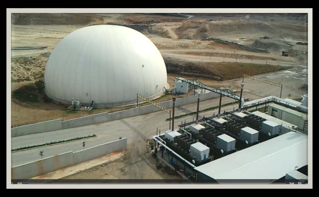
26 26

27 27 H 2 S REMOVAL UNIT H2S (Hydrogen Sulfide) contained in the biogas from the fermentation units needs to be removed in order to be fed to the gas engines.the treatment is carried out using chemistries. Image from H2S removal unit
28 28 BOOSTER UNIT Two booster units are used. One is used to take the gas in the fermentation unit and send it to the H2S unit and then to send it to the gas holders and the other one to send the gas to the gas engines. The Booster unit, which will be used to send gas to the motors, will be an online gas analyzer, flow meters, automatic control valves, pressure and temperature transmitters and flare. In this unit, all data will be recorded


29 29 Booster unit control panel and on-linegas analyser. Blowers

30 30 Booster unit inlet filters
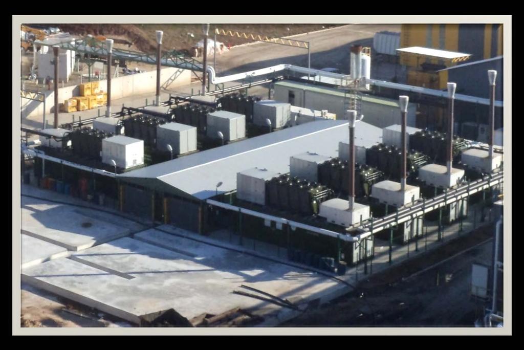
31 31 POWER PLANT Biogas can be used as fuels and also to produce electricity. The main composition of biogas is methane. Biogas possesses chemical energy, and therefore electricity from biogas comes as a result of converting this chemical energy to mechanical energy and finally into electricity. This is done by the use of transducers such as generators and turbines that convert energy from one form to another. This electricity can be used both domestically and commercially since it can be made in small and large scale. Power plant contains gas engines, step up/ down up transformers, substation and cogeneration unit. Gas engine waste heat can be use for heating of the fermantation units, green houses and offices.
32 32
33 33 TEŞEKKÜR EDERİZ