EQUIPMENT MANUFACTURING GENERAL
|
|
|
- Julian Chambers
- 5 years ago
- Views:
Transcription
1 2016 EQUIPMENT MANUFACTURING GENERAL FOR WATER & WASTEWATER SYSTEMS ENTA TREATMENT SYSTEMS
2 WATER FLOW CONTROL DEVICES Water flow control devices are designed to serve to a wide variety of duties. Selection of the correct device to suit the duty is important to overcome the design criteria and provide the most cost effective solution. The range of available operating equipment is extensive: from simple direct operation by hand wheel to complex control systems by electrical actuation. The range of water flow control devices with associated operating equipment will outfit the most demanding specifications and applications. ENTA designs and manufactures open channel or wall mounted Penstocks as well as other water flow control devices such as motorized adjustable tilting weirs, telescopic valves, inlet baffles and stop logs to fit various dimensioned apertures or channels. Penstocks for open channels or wall mounted types with three or four sided EPDM seals are designed for on or off seating pressure and equipped with rising or non-rising spindles which are operated manually or with actuators. Stoplogs are not only used for closing the water channel but also can be used for water level adjustment by adding or removing obturators inside the frame. Vertical or tilting adjustable weirs are mainly used to adjust the water level in distribution and aeration tanks. Telescopic valves are suitable for the flushing of superficial liquids for regulating or evacuating. Adjustable inlet baffles are generally used to obtain an efficient distribution and high settling efficiency in the cross flow sedimentation or grit removal tanks.


3 PENSTOCKS The control of the flows in the canals at the water and wastewater treatment plants is performed by the penstocks. ENTA produces penstocks assembled to the canal by its own design as being rectangular shape and from the material of carbon steel or stainless steel. Impermeability is provided by the use of P,V and double-lipped rubber seals beside the three sides of the penstocks. Also there is performed the special designs for the structures and special penstock production as proper to the demand.


4 SLUICE GATES /STOPLOGS Wall type penstocks are used to control the flows in the tanks at the water and wastewater treatment plant and to provide the isolation. At all designs of ENTA especially the impermeability is provided by the use of the P,V and double-lipped seals besides the four side of the penstocks and for 1 m seal length (at the pressure of 5 m on seat or 4 m off-seat), there is reached to the very low impermeability values as 0,4 liter/min. The wall penstocks have a wide size range and are designed specially as per the pressure applied and the distance to be closed. Stoplogs are the type of the penstocks which are used extensively in order to control the flow at the water intake structures and water and wastewater treatment plants. As the other types, stoplogs are produced from the material of stainless steel or steel and are durable to the effects of the wastewater. Stoplogs are produced in one-piece and also can be produced partially as segments at the applications required a more flexible usage by ENTA.


5 ADJUSTABLE WEIRS Adjustable weirs are mostly utilized for level control. The main feature that sets them apart from sluice gates is that they allow partial opening control. Furthermore, they may be opened downwards or in angles, as the main purpose is controlling the water level, as opposed to sluices gates that usually open upwards.


6 TELESCOPIC VALVE Telescopic valves which are assembled on the pipe, control the water inlet according to the water level inside the tank. These are preferred at the deep canals. Our manufactures are designed as stainless or carbon steel.
7 SCREENS The load of the treatment plants are significantly reduced due to the proper selected and correct operated screens. The selection of the appropriate screen is depending on the characteristics of the wastewater and also hydraulic calculations and topographical structure. By the purpose of producing appropriate and correct solutions as per the demands coming from our customers, everyday there is added a new one to the kinds of the screens at our range of products. Together with the increase of the screen demands, as being ENTA we turned a significant part of our design activities to the screening equipment. All our presented mechanical screens are available to be operated automatically depending on the difference of water levels or the time intervals which have been set.


8 MECHANICAL SCREEN This is the most widely used screen model as fine and also coarse screen at the large and medium sized treatment plants. These can operate at very deep canals as per the demand and without being any limitation of the canal height The main application areas are domestic and industrial wastewater treatment plants, lifting stations and water treatment plants. Linear mechanical screen is a mechanical equipment which is assembled to the ground of the canal with an angle of 750 and cleans the bar screen by combing vertically. Generally it consists of the chassis, fixed screen, scraping system and garbage container. The circular motion which is provided by the reducer which is driven by the electrical motor will be turned to the linear motion at 10 m/min. and transferred to the scraper palette. All the motions of the scraper palette are automatically controlled. Scraping motion starts from the bottom dead line and ends with the transfer of the wastes accumulated at the comber to the accumulation container by the motion of the opposite scraper at the top dead line. At this model, combing motion is continuous and there is no need of the microswitch etc. equipment to start the landing motion. At the landing time, the comber will change its position, and moves away from the screen. When the straight mechanical screen stops, the comber parks at the top position and do not prevent the water flow.

9 INTERNAL FLOW SCREEN Internal flow drum screens (IFD) which are produced for screening of the solids prone to settling, are in the group of fine screens. IFD; is a drum made of perforated metal sheet or mesh screen wire and consists of a bearing system, water distribution weir and water spray mechanism. By its fully closed structure, some problems like odor, spring etc. completely prevented. Screens are made from the material of stainless steel, epoxy painted or galvanized cover carbon steel. Screening ranges change between 10-80mm, and screen hole diameters change between 250µ-2mm. Drum screens separate all the solid particles bigger than the screen space from the liquid which will be filtrated. By its operation principle, it keeps the long fiber wastes, grit and grease at the pre-treatment and processes and gains advantage. Wastes are transferred continuously to the discharge part with the turn of the drum. From this part, they are poured to the conveyor or the transfer container which will be stocked. Drum screens are fully closed constructions. They do not cause any problems like odor and splashing. The energy consumption is very low and its cleaning and maintenance is easy. The surface of the screen is designed for being cleaned with the pressured water or hot water as appropriate to the process.


10 CABLE OPERATED BAR SCREEN The cable operated bar screen is fully automatic cleaning equipment. It can be used in the inlet channel of pumping station, wastewater treatment plant, power plant and desalination plant for the floating matters screening or bottom accumulation removal. The rake is traveled in lateral guide rails, by suspension on 3 cables-two for lifting/descending one for opening/closing-the rake can be brought into operation at any depth. On downward travel, the rake runs in open position within the guide rails. After reached the channel bottom or floating layer the rake movement is reversed by the automatic control of the cable slack sensor ; closed the rake travels upward with the trapped screenings. Above discharge chute, the screenings are discharged by wiper into a cart or onto belt conveyor. The rest position of the rake is above discharge chute. 1. Screen Grid, 2. Guide, 3. Rake, 4. Wiper, 5. Cable Drum, 6. Driving Unit, 7. Dead Plate, 8. Chute, 9. Steel Structure, 10.Platform, 11.Rake Pivot Assembly,12.Cable Slack Sensor,13.Local Control Panel, 14.Ultra-Sonic Level Sensor (Option) CH = Channel Depth, DH = Discharge Height, FL = Floor Level, WL= Water Level,BL = Channel Bottom Level MW = Machine Width, CW = Channel Width, GW= Grid Width, GH = Grid Height, MH = Machine Height


11 INTERNAL FLOW SCREEN MATERIAL Body : AISI 304, st-37 + Epoxy Drums : AISI 304 SS304, Chassis can be produced as St37 or SS304 or from any other material as appropriate to the project. Impellent group : Motor + reducer, if required, variator or frequency converter can be added. (Optional) Scraper Knife : The part of the AISI 304 stainless steel scraper arm which touches to the surface of the drum, consists of a bronze knife which is installed with bolts. In order to increase the press of the knife on the surface, it has a structure which can be arranged with an opposite weight. AUXILIARY EQUIPMENTS Besides different screening solutions, ENTA can produce screen conveyor, screen press and band conveyors as auxiliary equipment. CONTROL AND WARNING DEVICES Drum screen can be operated as automatically, time arranged. EXTERNAL FLOW SCREEN External flow drum screens (EFD) which are produced for screening of the solids prone to swimming, are a kind of fine screens which are used at domestic and industrial wastewater treatment plants and also are safely used at the process wastes of the industries like leather, food, paint, textile, paper, sugar etc. These screens operate by collecting the screened material at the external surface of the drum. This screen drum is gained by the wires with V sections wrapping as spiral by a special device and welding with high frequency. By this gained section, the blockage of the screen is almost impossible and its permeability ratio is very high. Wastes collected at the external surface of the screen drum, are scraped by a scraper knife and discharged to a collection box or directly to the conveyor system. Against the possible blockings, there is found a pressure water spraying system at the internal surface of the screen drum.


12 STATIC SCREEN Static screen is a fine screen equipment which has a self-cleaning and can make screening by the gravity without needing any impellent group. Static screens (STS) especially used in the wastewater treatment plants of the industries like textile, paper, food, alcohol. This equipment consists of a water distribution weir and a screen system which is made from stainless steel wires with V section. The usage of this equipment is very easy and almost does not need any maintenance.


13 HELICAL TYPE CANAL SCREENS Helical screen is a kind of fine screen which is used especially in the open canals with less width. Those are used in domestic and industrial wastewater treatment plants and also can be used in process water preparation plants of many industries. Helical canal screen consists of a cylindrical screen wire and a spiral that cleans the screen. Those could be placed at low angles due to its location of working and the wastewater canals. Screen wire could be made as perforated or wedge-wire. The substances which are kept on the screen at the time of screening shall be lifted by the screw conveyor and also could be discharged from the screen by pressing. It operates by time control, level control or both time and level control. HELICAL TYPE CANAL SCREENS ARE PREFERED BECAUSE OF TAKING UP LESS SPACE, THEIR DURABLE MANUFACTURING AND GOOD SCREENING PROPERTIES THESE SCREENS WHICH CAN MAKE SCREENNG TO 1-6 MM, GAIN ADVANTAGES OF EASY ASSEMBLY AND PRACTICAL REMOVAL OF WASTES. ASSEMBLED SYSTEM AT THE OUTSIDE OF THE BUILDING ASSEMBLED SYSTEM AT THE INSIDE OF THE BUILDING

14


15 GRIT BRIDGE SCRAPER Rectangular type grit chambers are used extensively in wastewater treatment systems as aerobic and anaerobic. In order to remove the solids which are settled at the bottom of this kind grit chambers, there is used scraper systems. By the scrapers which move two-way through the grit chamber, the grits are pushed to the drain at the bottom of canal and from here are taken from the tank by sucking with the submersible or air lifted pumps. This sludge mixed with water, is removed from the organics inside generally by passing through a grit washing or classifier unit and are collected in sand containers and removed out of the plants. Scrapers of the grit chambers can be arranged in order to scrape a single, two, three or four canals. At small plants, grit washing unit can be installed on the bridge of the scraper.

16 DETRITOR The ENTADT grit separator is used at the raw inlet and should be positioned downstream of the sewage screens. These screens will have medium fine spaces.where two stage screening is applied ENTADT system can be installed after the medium spaced screen thus offering protection to the fine thus screening mechanism from abrasive detritus. The collection tank is a wide shallow channel of square proportions. The inlet channel is near parallel to the inlet side of the tank and has a series of vertical baffles to assist with the distribution of flow entering the collection tank. The chamber design enhances the equalization of the flow across the chamber. Flow is in a singular direction across the tank to the outlet side. The outlet is a sharp edged weir which has a drowned discharge during the higher flow rates. The normal form of hydraulic control is a Standing Wave Flume, this doubles as the means of flow measurement. The characteristics of the flume are ideal to control the critical crossflow velocities within the trap. The flume will be positioned downstream of the Crossflow chamber in accordance with its specific requirements. A recessed, circular sump is formed. The level floor of this sump is the bed upon which the grit and other similar solids will settle. This accumulation of solids is collected and transported by a slowly rotating scraper mechanism supported on the bridge spanning the tank. The collected solids are delivered to a hopper on the periphery of the tank; from here the grit is separated and dewatered by a Classifier. Various methods of grit classification are available. These are selected by preference, site limitations and in some instance the effectiveness of the primary screening. Efficient operation will be achieved when the velocity over the whole range of flow is maintained at a specific value. It is at this velocity that grits of the specified size and specific gravity will be collected. Sizing, positioning and hydraulic control are of the utmost importance.


17 SCREW GRIT CLASSIFIER Grit classifiers are used for pressing, dewatering and decreasing the volume of the wastes which are collected by the screens. Thus, this make easy the transportation of the wastes and gains savings. This needs less maintenance by its simple design, strong body structure, pressing screw durable to detrition, bearing system that meets all loads and its reducer. OPERATION PRINCIPLE Liquid addition is done to the sedimentation part. Material which settles rapidly inside the liquid, reaches into the bed in which the spiral operates. The operating screw separates the settled material for example, sand, from the liquid by a specific angle and reaches to the discharge part and from here it is discharged into a container. The liquid which is separated from its solid, is discharged by passing through an overflow. This equipment does not have any element which requires any maintenance like lower bed. MATERIAL : body: st 37 or AISI 304 screw: special steel durable to corrosion corrosion plate : technical plastic durable to corrosion motor: completely closed box WASHING SYSTEMS

18 RECPROTATING RAKE CLASSIFIER THE RAKE CLASSIFIER CONSISTS OF RECIPROCATING RAKE MECHANISM SET IN AN INCLINED CHANNEL ALONGSIDE THE GRIT COLLECTION BASIN. THE SMOOTH AGIGATION OF GRIT CAUSED BY THE LOW SPEED MOTION OF THE RAKE MECHANISM PROVIDES A PERFECT ENVIRONMENT FOR THE SETTLED GRITS TO LIBERATE PUTRESCIBLE ORGANICS, LEAVING CLEAN GRIT FOR DISCHARGE AND REDUCED ODOUR PROBLEMS THE RAKE CLASSFIER CAN BE SITED ADJACENT TO THE POINT OF GRIT COLLECTION. THE CLASSIFIER IS DESIGNED TO RECEIVE A GRIT AND WATER MIXTURE BY GRAVITY FROM A FLAT BED GRIT COLLECTOR. THE UNIT CAN ALSO BE STANDALONE IN EITHER A CONCRETE OR STEEL FABRICATED CHAMBER. THIS CAN BE FED BY A PUMP RISING MAIN. THE PUMP CAN BE OF THE CENTRIFUGAL TYPE, POSITIVE DISPLACEMENT OR AIR LIFT. WHEN THIS OPTION IS PREFERRED A RECEIVING HEADER BOX IS POSITIONED ON TOP OF THE UNIT TO ENSURE THE CORRECT PATTERN OF FEED IS ACHIEVED OPERATING PRINCIPLE: IN A DECLINED TROUGH, THE COARSE MATERIAL IS SCRAPED UPWARDS BY A RAKE. AT THE RETURN POINT, THE RAKE IS LIFTED, MOVED BACK DOWN TO THE INITIAL POSITION AND LOWERED ONTO THE BOTTOM OF THE TROUGH. THE FINE MATERIAL REMAINS SUSPENDED AND FLOWS OUT OVER A WEIR AT THE LOWER END OF THE TROUGH. THE SLURRY-FEED INTAKE IS LOCATED ABOUT A THIRD OF THE WAY UP FROM THE LOWER END OF THE TROUGH


19 OUR RAKE CLASSIFIER IS USED FOR GRIT REMOVAL IN VARIOUS PROCESSES. IT IS MADE OF MILD STEEL AND HAS A COMPLEX MOTION TRANSMISSION MECHANISM WHICH IS HIGHLY EFFECTIVE. OUR RANGE OF GRIT REMOVAL EQUIPMENT CONSISTS OF CROSS FLOW DETRITORS UP TO 12.0M DIA, TRAVELING GRIT DREDGERS AND COMBINED GRIT AND GREASE REMOVAL. IN ADDITION TO GRIT REMOVAL PRODUCTS THERE IS A CHOICE OF GRIT CLASSIFICATION UNITS OF THE RECIPROCATING RAKE TYPE AND THE SCREW CLASSIFIER TYPE.
20 SCRAPERS & THICKENERS

21 CIRCULAR BRIDGE SCRAPER ENTA design, manufacture and install a range of scraper bridges for all types of circular settlement tanks with diameters up to 60 meters. In all cases the structures are designed by ENTA s engineers to withstand all of the loads and stresses placed upon the bridges and manufactured to the highest of engineering standards. All superstructures and underwater assemblies are protected to customers specification. Circular type The most common form of circular tank scraper is the rotary half bridge This is mounted on a central slewing bearing supported on a tripod assembly and is driven by an end carriage travelling around the periphery of the tank. In addition to the standard half bridge scraper, ENTA manufacture twin and triple arm rotary machines. Small bridges are manufactured using a beam structure whereas larger bridges require a lattice or girder structure which gives the required strength without excessive weight. All bridges are manufactured in either steel, which can be finished to customers specification, or aluminum. The end carriage unit incorporates a small electric motor and gearbox which drive onto the peripheral wall via a cast iron wheel fitted with a polyurethane tyre. The unit is designed to give a peripheral speed of between 1.0 and 2.0 meters per minute depending on machine design.

22 CIRCULAR BRIDGE SCRAPER Scraper blades are designed in a helical curve formation which maximizes scraping efficiency and thus sludge removal. Scraper blades are hinged 400mm above the floor of the tank, an arrangement which provides for a more positive scraping action. Scum removal can be effected by using a number of different scum removal systems, ENTA can supply a ramp type, and rotating box type. Channel Cleaning All rotating bridges can be fitted with any of the following types of channel cleaning systems: Rotary Brushes Pressure Washers Chains Fixed Brushes Hydraulic lift Scrapers This is a design of rotating half bridge scraper specifically designed for use in flat bottomed final settlement tanks. The scraper blades, consisting of linked individual Vee formations, have a tube leading from the apex of the Vee up to the trough, suspended from the bridge so that its base is below top water level. Because this creates a head differential, the sludge collected in the Vees by the rotation of the bridge is simultaneously conveyed up into the trough. As this is a continuous action, there is no sludge build up in the bottom of the tank. The rate of discharge can be varied from each discharge tube by having adjustable bellmouths fitted to the top of each top. Sludge is removed from the trough by a siphon discharging into a collection system within the central assembly.


23 SCRAPER BRIDGE DETAIL OF SCUM BOX SUBMERSIBLE BUFFLE & WEIRS


24 LINEAR BRIDGE SCRAPER Linear scrapers which are used in rectangular basins, mostly preferred as grit and oil chamber at pre-treatment plant. It is possible to make different groups for linear scrapers as circular ones. Energy feeding can be done by a cable drum or with cable trolley. Removal of the sludge settled at the bottom, shall be done by an air-lift system and also can be performed by a pump on the bridge. Along the sucking types, there are some applications as scraping the sludge from one point to another of the canal by the scraper knifes installed to the bridge.

25 THICKENER Those can be designed as fixed bridge or rotating bridge as being at the circular scrapers. In order to fasten the sedimentation of the solids, there are found additional bars at the basin. ENTA thickeners are varied according to the tank geometry, tank diameter and the characteristics of wastewater. Scraper and thickeners could be produced from stainless steel, epoxy painted or galvanized cover carbon steel.
26 SLUDGE DEWATERING SYSTEMS An expert group including machinery manufacture engineers and process technology experts, is ready for your serve to produce practical and economical solutions for the dewatering problems special to you. Our services start with comprehensive test studies at our laboratories and continue with site tests which will be done by our pilot plants and last until the commissioning and handing over of the plant. As a result of continuously developing, now we are presenting the reliable designs with only advanced technology and also presenting the design, engineering and projects services of complete dewatering plants. By this reason, when our clients buy an ENTA plant, they know that this is based on years of experience and their demands will be met as certain and reliable.


27 BELTPRESS Belt filter presses are indispensable for years as an economical dewatering method especially at the places with high sludge flow and because of their operation principle. We are producing beltpresses in order to offer adequate solutions for every kind of sludge which is difficult to be dewatered and has different content and structure. The chassis and drums of the beltpress have a durable structure against the loads. Because of all beds on it being waterproof and incorrodible, there is no need of maintenance. Maximum dry of the cakes are provided with different pressure stages and the amount of the solids at the filtrate is minimum. Through the automatically cleaned nozzles, there is gained an efficient belt washing operation and also this is one of the most important factors that effects the capacity of the beltpress positively.

28 FILTER PRESS Filter press is one of the most effective method of the separation of the solid-liquid and used in every kind of application. The application areas of the filter presses with plate-frame, chamber and membrane plate are very various. By the increase on the filtration demand, we have directed a significant amount of our production to the filtration equipment. Our filter presses are designed to meet the highest capacity for the given plate dimensions and cake thickness. The other factors which affect the capacity directly are : Quick cake discharging by the automatic plate opening device Time savings on the cleaning of the filter cloth by automatic washing device Opening and closing of the filter presses within short time cycle period Because of being the materials and instruments used on the filter press, high quality, the service demand of the filter press is very less and its maintenance is very easy. Major Components Frame - Welded steel construction with removable side rails, fixed head leg end and tail leg end with integral control panel and hydraulic cabinet. Leg extensions for drum sludge removal. Closure - Hydraulic ram fixed at tail end and movable follower. Manual hand hydraulic pump with gauges and valves. Plates mm, 630mm, 800mm 1000mm Filter Cloths - Many options for different applications Blowdown Manifold - PVC, CPVC and SS pipe connections and valves with separate air regulatormounted on filtrate discharge. Depending on the water retention tendencies of the solids, concentration of the final filter cake may range from 20 percent to more than 40 percent solids. To maximize solids content and aid cake removal, the air blowdown manifold purges chambers of excess filtrate and partially dries the cake. Presses come equipped with manual or air-driven hydraulic closure mechanisms, and are available in both custom and engineered sizes.


29 Enta Filter presses are not only used in dewatering of the sludge of domestic and industrial wastewater and water treatment, also found place in process application of most industries. Some of these industries are : Chemical product manufacturing Ore processing and enrichment Soap and oil production Sugar beet processing and colorant production Paint production Liquid and solid oil and plastic production Ceramic Industry Beer, liqueur, wine and yeast production Phosphate coating baths


30 MIXER Mixing of the coagulant and chemicals with water is performed by ENTA mixer and flocculators. All impellent groups, motor, reducer and general project have a long life and strong structure. Mixer and flocculators shall be produced as coated (rubber, teflon, rilsan etc.) carbon steel or painted carbon steel, galvanized coated carbon steel or stainless steel. All these selections should be done as adequate to the process by ENTA.
 polyelectrolyte there is needed to make it solution. This unit which is designed to gain ease of operation, will operate full automatically with the depot.")
31 POLYELECTROLYTE MAKE-UP UNIT Polyelectrolyte which is used as flocculants is mostly used in potable water and wastewater treatment. Usage Type : Polyelectrolyte is supplied as dry-liquid. In order to use the dry (dust) polyelectrolyte there is needed to make it solution. This unit which is designed to gain ease of operation, will operate full automatically with the depot. The series POLY-AUTO is produced as Standard against the demand. The solution concentration at the unit applied from 500 L/h to 4000 L/h, can be arranged from % 0,05 to % 0,5.


32 CONTROL PANEL & PLC & SCADA EPANEL is the brand name for the panels manufactured by our company. The panels are manufactured with outmost care while providing project support and performing routine tests.

33 SCADA
34 WATER TREATMENT SYSTEMS In the water we use in every area of our daily lives and in the industrial plants, there is asked for various properties depending on the usage area. At the treatment of the potable water which affects directly the human health, the factors like the mineral wealth and disinfection of water, and also odor, taste and color have to be considered. Water treatment in industrial plants are important to prevent the fittings and equipment to be damaged because of the substances inside the water. By this purpose, some of the materials some of the main parameters to be removed are ; hardness, alkalinity, total dissolved material and silica. The methods and Technologies which are used for this purpose are as explained at the following pages. ENTA ; gives services from just equipment sales to the projects and installing turnkey treatment plants.


35 WATER TREATMENT SYSTEMS The capacities of the pressured filters change between 5-100m 3/hour and are used in the applications of process water, pool water, and irrigation water. Filters are selected as per their intended use, and names according to the filling material inside as multimedia filter, activated carbon filter, ion exchanger etc. According to the used filter material, those are used to remove the SS (Suspended Solids), turbidity, iron, manganese, free chlorine, odor and color inside the water. ENTA produces all equipment used by the purpose of filtration. Sand Filters : Inside the cylindrical steel tank, which is designed as vertical or horizontal according to the necessary capacity, there is found steel plates in which the filter nozzles are installed, gravel bed and filling materials formed to prevent the blocking of the nozzles. The combinations formed of quartz sand and anthracite at adequate grain diameter, are used as filling materials. The cambered steel tank is designed according to the necessary operation pressure. The main intended uses are ; the removal of SS and turbidity.


36 WATER TREATMENT SYSTEMS Activated Carbon Filters : Inside the cylindrical steel tank, there is found steel plates in which the filter nozzles are installed, gravel bed and filling materials formed to prevent the blocking of the nozzles. The type of the activated carbon which will be used as filling material, changes according to the applications. The cambered steel tank is designed according to the necessary operation pressure. The main intended uses are ; the removal of chlorine, organics, odor and color. Iron and Manganese Filters : The factor which separates these filters from the sand and activated filters is the difference of the filling material. By the oxidant property of this filling material, the dissolved manganese and iron can be filtered. Water Softening: With the ion exchanging method, there is gained soft water by the calcium and magnesium (which cause to hardness inside the water) passing through a strong resin and being kept. ENTA water softening equipment ; is a complete with the resin tank, salt cup and piping mechanism.


37 Demineralization: This is the process of the removal off all cation and anions found inside the water and cause to conductivity. By this purpose there two main methods : ion exchange and reverse osmosis Ion exchange: This is the process of all cations and anions inside the water being passed through the cationic and anionic resins and kept. The free chlorine inside the water has to be removed by the addition of degasifier according to the analysis of raw water. Reverse Osmosis: This is used in order to gain demineralized water by the water passing through a semi permeable membrane system under high pressure. Reverse Osmosis is used in treatment of well water and surface water and also sea water which has high salinity. There has an important effect of the plant design and also pre-treatment at the supply of the predicted capacity and the life of the membranes used in reverse osmosis plants. That s why, Reverse Osmosis system has to be designed together with the pre-treatment equipment. The pretreatment equipment are specified and discussed by us according to the source and characteristics of raw water and the type of the membranes used in Reverse Osmosis unit.


38 BELT & SCREW & SWAN NECK CONVEYOR These are the equipment which are used to carry the materials like screenings, lime, sludge cake etc. from one place to another. We can gather our conveyors selected due to the carrying height, angle and distance under three main titles: Belt conveyor Screw conveyor Swan neck conveyor By calculating according to the belt width, screw diameter and palette length, we present the most economical and adequate solution alternative. BELT TYPE CONVEYOR SWAN NECK TYPE CONVEYOR
39 AERATORS The efficiency of the biological treatment plants is mostly due to the quality and accordance of the used aerators. The most important factors on the selection of the aerators are ; the dimensions of the basin, the amount of the necessary oxygen and the effect of mixture. Based on the reliable assessments from our many applications related to this equipment, we guarantee all kind of efficiency of our aerators.


40 SURFACE AERATORS The efficiency of biological treatment plants depends considerably on the quality and suitability of the aerator used. The major factors to be considered in the selection of aerators are the basin dimensions, the required amount of oxygen and mixing. We guarantee the efficiency of our aerators in all aspects on account of sound evaluations of our numerous applications of this equipment. Vertical shaft aerators, are among the most efficient aerators. The simple mechanical structure consisting of actuator, shaft and fan allows easy operation. It can either be easily mounted on fixed bridge, or be attached to the side of the basin by means of a special barge system in cases where water level can vary. They are produced in 18 different models, varying in capacity and fan diameter depending on motor power changing between kw. In cases where the basin geometry is unsuitable, they may necessitate the use of such accessories as suction pipe, suction nozzle and baffle.


41 FUCHS TYPE AERATORS HIGH EFFICIENCY OF MIXING * LOW ENERGY CONSUMPTION *OPERATION AT VERY LOW LEVELS * HIGH OXYGEN EFFICIENCY WITH LOOP AREATION SYSTEM AND MINI BUBBLES * EASILY ASSEMBLY AND DISASSEMBLY * MINIMUM MAINTENANCE DEMAND * BY SPECIAL IMPORTED SIEMENS MOTOR *WEIGHTS BETWEEN KGS * SUSPENSION SYSTEM WHOSE ANGLE IS ADJUSTABLE * THE POSSIBILTY OF INDEPENDENT USE FROM THE WATER LEVEL BY FLOAT * NO LOSS OF ACTIVATED SLUDGE AT THE TIME OF MAINTENANCE AND REPAIRING


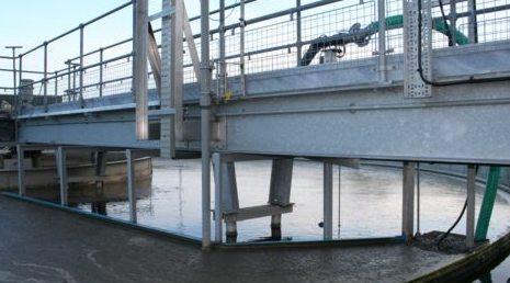
42 Wastewater Clarification, or sedimentation, is a common and essential process in municipal and industrial wastewater treatment plants. Clarifiers consist of tanks or basins which hold wastewater for a period of time, allowing solids or other materials suspended in the water to settle to the bottom. CLARIFICATION TANK


43 COMPACT UNIT Chemical Preparation Systems All types of industries for dosing chemicals such as: Sulphuric Acid - ph Correction/Control Caustic - ph Correction/Control Sodium Hypochlorite - Disinfection Aluminum Sulphate - Coagulation Ferric Sulphate - Coagulation Ferric Chloride - Coagulation Synthetic Polymers - Used water, effluent and sludge treatment Organic Coagulants - Coagulation Chlorine Disinfection System Chlorination is the process of adding the element chlorine to water as a method of water purification to make it fit for human consumption as drinking water.


44 AIR BLOWERS Air Blower System Blowers in wastewater treatment plants function as a good air diffuser system. There are basically two different types of blowers used in today s treatment plant like the Centrifugal Blower and another type is the Positive Displacement Blower.


45 PUMPING SYSTEM Centrifugal Pumps Applications: Water supply, irrigation, process plants, chemical, pharmaceutical, cosmetic, paper, textile, construction, plastic, rubber, paint, drink, sprinkler, liquid circulation, central heating, power plants, water treatment, refrigeration. Motor: Protecting Class: IP 55 or IP 54 Single-phase version: 220 V,50 Hz Three-phase version: 380 V, 50 Hz


46 Submersible Pump Submersible pumps have found their uses and applications in places where any fluid needs to be drained or pumped out. bore wells Drainage Sewage pumping Slurry pumping General industrial pumping Pumping water from Mono Pump They are commonly used in pumping municipal sewage sludge, mine waste water and slurries. Booster Pump Booster pumps are designed to smooth out water pressure in areas where the flows are highly variable. This type of pump is essential in water management systems and is used in a wide range of public and private settings.


47 DOSING PUMPS Applications: Water and sewage treatment: Sampling, chemicals dosing: Ferric Chloride, Sodium Hypochlorite, Sodium Bisulphite, etc... Abrasive products dosing: Lime slurry, Carbon slurry, Potassium Permanganate, etc. Polymers, Aqueous Ammonia, etc.


48 UNIT ACCESSORIES Pneumatic Actuator Used to provide dependable and smooth operation in demanding process control conditions. Electromagnetic Flowmeter Used to chilled water, hot water, domestic water, condenser water and boiler feeds. VALVES Butterfly Valve Check Valve Ball Valve Gate Valve


49 Chlorine Dosing Unit Chemical Preparation Tanks
 H 2 S (Hydrogen Sulfide) SO 2 (Sulfur dioxide) NOx Compounds Chemical odor control units are based on the scrubbing of the odor causing emissions to change")
50 ODOUR CONTROL SYSTEMS Odor Control units are used in; All liquid treatment plant processes Pump stations, Sludge thickening, Sludge dewatering. Main Odor Causing Compounds; NH 3 (Ammonia) H 2 S (Hydrogen Sulfide) SO 2 (Sulfur dioxide) NOx Compounds Chemical odor control units are based on the scrubbing of the odor causing emissions to change molecular structure of compounds. Control units are natural odor neutralization processes, works on the principle of chemical destruction of odor causing compounds. Odor control units can be designed and produced in Chemical scrubber type. Components of Chemical Systems Vacuum Fan Scrubber Chemical Matter and Dosing System

51 CHEMICAL SCRUBBERS The basic components of the scrubber are the vessel; packing material; liquid recirculation system with spray nozzles, recirculation pump, a sump; and a mist eliminator. A fan draws or pushes the odorous air into the scrubber. The air passes through the packing bed where it comes in contact and is absorbed into the liquid solution sprayed from nozzles above the packing bed. The liquid solution, after passing through the packing bed, falls into the sump, where it is recirculated or discarded. Chemical scrubbers are a common odor control technology. The basic objective of a scrubber is to provide contact between odorous air, water, and chemicals to provide oxidation or entrainment of the odorous compounds. The odorous compounds are absorbed into the scrubber liquid, where they are oxidized and/or removed from the scrubber as an overflow or blowdown stream. The air exits the packing bed and is routed through the mist eliminator to minimize liquid droplets from exiting the scrubber. Typical chemicals used in the liquid solution to oxidize NH 3. An ORP probe and controller maintain the proper chlorine residual by regulating the rate sulfuric acid is added to the solution. The oxidation reactions are dependent on ph, with the optimum scrubber solution ph being in the 3 5 range. In this range, NH 3 is absorbed into the recirculation liquid. As ph increases below the optimum range, the NH 3 solubility increases and is not effectively absorbed into the scrubber solution. As ph decreases above the optimum range, more chemical is used than necessary, and more carbon dioxide is scrubbed from the air stream. The scrubber chemical concentrations are typically automatically controlled by monitoring the liquid solution ph. A ph probe and controller maintain the proper ph by regulating the rate sulfuric acid is added to the solution. The ammonia reacts with the sulfuric acid to form ammonium sulfate, a soluble, nonvolatile salt, which is removed from the scrubber effluent through the overflow.

52 Air Fans Our supplies only the highest quality exhaust fans for all of our air pollution control applications. With airflow volumes from 100 to over 100,000cfm, fans can be constructed from FRP, coated carbon, stainless steel, or a variety of exotic metals. Fans can be either centrifugal or axial configuration. The interior of the fans is always coated with a corrosion resistant materials to provide for years and years of dependable service. Chemical Dosing System Our Chemical system comprises a range of automated dosing units from small to large capacity. The range of sizes enables: A whole-of-system approach to odor and corrosion control from low-flow to high-flow sections of the sewerage network Cost effective odor and corrosion control for small and large sewerage systems Precise targeting of septic flow sources Specifically designed systems to suit your needs Effective control of OHS and environmental issues


53 Benefits Suitable for long rising mains or pressure sewer systems Reaction is irreversible Precise dose can be administered at precise time it's needed Equipment is cost effective Suitable for variable grade pipelines Reduces odor and corrosion Reduces capital expenditure Reduces customer complaints Tailored dosing


54 CIRCULATION PUMPS

55 CHEMICAL STORAGE & PREPARATION PLANTS

56 ALWAYS BEST SOLUTION