FCC Regenerator Design to Minimize Catalyst Deactivation and Emissions. Steve Tragesser Shaw Energy and Chemicals Group
|
|
|
- Anna May
- 5 years ago
- Views:
Transcription

1

2 FCC Regenerator Design to Minimize Catalyst Deactivation and Emissions Steve Tragesser Shaw Energy and Chemicals Group
3 Shaw Stone & Webster FCCs 42 RFCC/FCC/DCC Units Licensed Resid RFCCs (R2R) Other FCC/DCCs (R1R)
4 Regenerator Design Objectives Effective regeneration of catalyst Minimum catalyst deactivation Efficient use of available air blower capacity Minimum damage to equipment Minimum toxic emissions
5 Typical Regenerator Designs REGEN Spent Catalyst REGEN Spent Catalyst Air Counter-Current Regeneration Air Co-Current Regeneration
6 Typical Co-Current Regenerator Regenerator Reactor Spent catalyst Air
7 Typical Counter-Current Regenerator Reactor Regenerator Spent catalyst Air
8 Interior Particle Temperature Rise % C 20% O 2 (Co-Current) Temperature Rise, F % C 5% O 2 10% C 5% O Time, Milliseconds (Counter-Current)
9 Afterburn Burning of CO Above the Regenerator Bed 1. Can occur in dilute phase, cyclones, plenum chamber and/or flue gas line 2. Temperatures can damage regenerator internals 3. Can be limiting temperature in regenerator
10 Spent Catalyst Distribution
11 Spent Catalyst Without Distributor
12 Elimination of Serious Afterburn Problems Principle Causes Spent Catalyst Distribution Air Distribution Shallow Bed Solutions Distribute Spent Catalyst Across Bed Minimum Bed Height (3 5 meters) Air Distribution Multiple Rings Pipe Grids

13 Spent Catalyst Distribution Poor catalyst distribution Even catalyst distribution High coke concentration Side Entry Regenerator No Distributor Axens/Stone & Webster Distributor

14 Bathtub Spent Cat Distributor
15 Bathtub for Counter-current Regeneration and Low NOx

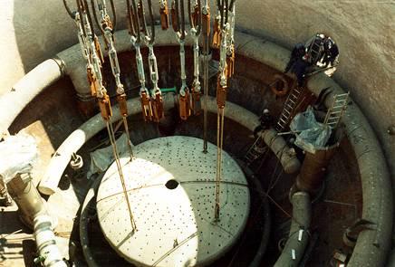
16 Spent Catalyst Distributor

17 Bathtub Spent Cat Distributor

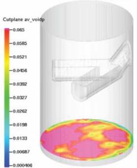
18 Bathtub CFD Modeling
19 Combustion Air Ring Cross Section of Ring Cross Section of Tee
20 Air Ring Installation

21 Air Ring Nozzle Layout
22 Two Stage Regeneration The Key to Resid Processing Why Two Stages for Resid? Heat balance control for high concarbon feeds Minimizes catalyst deactivation for severe regeneration required Lower average catalyst particle temperature Less hydrothermal deactivation Less vanadic acid deactivation
23 Two Stage Regeneration Concept 1. First stage regenerator design Countercurrent Regeneration Heat Removal Via CO Production (partial burn) 2. Second stage regenerator design Complete combustion Minimum moisture

24 Catalyst Cooler

25 R2R with Catalyst Cooler Catalyst Cooler SRC Singapore
26 Regenerator Emissions Particulates CO SOx NOx
27 Primary Causes of Particulate Losses Catalyst Attrition Fracture Abrasion Cyclone Design High Superficial Velocities Damaged Equipment Air Distributor Cyclone System Operation Bed Level High Velocity Nozzles
28 Final Particulate Removal Options 3rd stage cyclonic separation (80 mg/nm 3 ) 3rd stage cyclonic separation with 4 th stage underflow filter (50 mg/nm 3 ) Wet gas scrubbing (10 to 20 mg/nm 3 ) Electrostatic precipitation (10 mg/nm 3 ) Physical filtration (less than 10 mg/nm 3 )
29 Reactor BP Kwinana Flue Gas Filter Regen 3 rd rd Stage Separator Waste Heat Boiler Flue Gas Filter by Pall Orifice chamber Stack 330 mg/nm3 2 mg/nm3 R2 R1 140 mg/nm3


30 BP Kwinana Flue Gas Filter Tubesheet Installation Overview Pictures courtesy of Pall
31 SOx Strategies Minimize Coke Yield (Reaction technology) Use Desox additive to control small amounts SOx Use scrubber to control large amounts SOx Avoid Recycle of heavy streams

32 Wet Gas Scrubbing for SO x Removal Belco s EDV Wet Gas Scrubber
33 FCC Variable Affecting SOx Emissions and Additive Performance Variables Feed Stock Type Recycle streams Fresh Catalyst Equilibrium Catalyst Circulation Rate Regenerator Inventory Regenerator Operation Regenerator Temp. Reactor Temperature CO Promoter Usage Additive Addition Stripper Operation Effect on Sox Additive Performance Level and type of sulfur in feed Usually heavy coke-sulfur forming Higher alumina improves SOx efficiency Activity and additives present (SOx & CO) Higher rate improves efficiency Larger inventories reduce efficiency Increasing excess O 2 improves efficiency Increase favors SO 2 oxidation, hinders SO3 absorption Higher temp. favors reduction of sulfates to H 2 S Increasing CO promoter improves efficiency Near-continuous addition improves efficiency Poor stripping will increase SOx
34 NOx Control Very complex Related to feed nitrogen, not combustion air High platinum CO promoter & excess oxygen amplifies NOx Much of NOx is reduced to N 2 or leaves as NH3, HCN, etc. (70 95%)
35 Comparison of NOx Emissions in Commercial FCC Regenerators % N in Coke to NOx Counter-Current (Swirl) Counter-Current (Bathtub) Excess Oxygen in Flue Gas
36 Optimum Regenerator Design Turbulent bed Countercurrent regeneration Minimum excess oxygen Spent catalyst distributed across entire bed Minimum gas residence time of 4 seconds
37 Thank You The Shaw Group Inc.