Ash related challenges from a boiler manufacturer s point of view. FPK II course 2016 Sonja Enestam
|
|
|
- Alicia Richardson
- 5 years ago
- Views:
Transcription
1 Ash related challenges from a boiler manufacturer s point of view FPK II course 2016 Sonja Enestam
2 Contents Valmet Technologies Fuels Trends Challenges Ash related challenges Fouling and slagging Bed agglomeration Corrosion The significance of corrosion How do we tackle issues of corrosion? - Questions and solutions Case Naantali 2

3 Valmet Leading global developer and supplier of process technologies, automation and services for the pulp, paper and energy industries


4 Converting renewable resources into sustainable results Endproducts Biogas Biofuels Biochemicals Biomaterials New paper grades Heat Electricity Diss pulp Chem pulp Mech pulp Paper Board Tissue Services Energy Pulp Paper Automation Technologies Raw materials Waste Agro Wood Recycled paper Customer industries Energy production Biofuel refining Pulp Paper Valmet
5 Valmet s Road to Becoming a Global Market Leader 1797 Tamfelt 1856 Tampella 1858 Beloit 1860 KMW 1868 Sunds Defibrator 1951 Valmet Several M&As i.e KMW 1987 Wärtsilä paper finishing machinery 1992 Tampella Papertech End of 2013 Demerger to Valmet and Metso 1942 Rauma- Raahe Several M&As 1999 Metso created through merger of Valmet and Rauma Key acquisitions 2000 Beloit Technology 2006 Kvaerner Pulping Kvaerner Power 2009 Tamfelt 5 December Valmet
6 Unique offering covers process technology, automation and services Paper Recycled fiber lines Tailor-made board and paper machines Modularized board and paper machines Tissue production lines Modernizations and grade conversions Standalone products Pulp and Energy Complete pulp mills Sections and solutions for pulp production Multifuel boilers Biomass and waste gasification Emission control systems Biotechnology solutions e.g. for producing bio fuels Services Spare parts and consumables Paper machine clothing and filter fabrics Rolls and workshop services Mill and plant improvements Maintenance outsourcing Services energy and environmental solutions Customer Automation Distributed control systems Quality control systems Analyzers and measurements Performance solutions Process simulators Safety solutions Industrial Internet solutions Focus in customer benefits Valmet
7 Key figures 2015 Orders received EUR 2,878 million Net sales EUR 2,928 million EBITA before NRI 1 EUR 182 million EBITA margin (before NRI 1 ) 6.2% Net sales by business line 23% 39% Net sales by area 10% 13% 21% 11% Employees 12,306 Market position #1-2 Services #1-3 Pulp & paper automation #1-2 Pulp #1-3 Energy #1 Paper, board, tissue 31% Services Automation Pulp and Energy Paper 8% 45% North America South America EMEA China Asia-Pacific 1) NRI = non-recurring items Stable business = Services and Automation business lines Capital business = Pulp and Energy, and Paper business lines Valmet
8 Strong global presence close to our customers 140 locations in 33 countries Over 100 service centers 80 sales offices 34 production units 16 technology centers Valmet location Valmet

 Biomass and waste gasification Oil and gas boilers Waste heat")


9 Our pulp and energy technology offering Pulp Recovery Energy Biotechnologies Wood handling systems Cooking systems Complete fiber lines Pulp drying systems Evaporation systems Recovery islands Circulating fluidized bed boilers (CYMIC) Bubbling fluidized bed boilers (HYBEX) Biomass and waste gasification Oil and gas boilers Waste heat recovery Air pollution control systems Pyrolysis solutions for bio-oil production LignoBoost for lignin extraction Steam treated pellets production lines Biomass prehydrolysis for further refining to fuels or chemicals 300 complete fiber lines and 350 recovery islands delivered 400 boilers and environmental protection systems delivered Valmet

10 Fuel use in electricity and heat production in Finland Combustion DD DD DD 10 9 March, 2016 Valmet Author / Title Source: Statistics on production of electricity and heat, Statistics Finland and Electricity statistics, Finnish Energy Industries

11 Bio-energy technologies are in transition agro waste heat wood Combustion steam peat electricity fossil heat agro waste wood peat fossil Fuel handling and pre -processing Combustion Gasification Pyrolysis Torrefaction steam electricity Bio gas Bio oil Bio coal New bio products LignoBoost Lignin Chemical or biochemical Ethanol 11


12 The trend: From coal and peat to biofuels and recycled fuels Coal Peat Agro Wood chips Recycled fuel Forest residue 12


13 Parameters steering the fuel choice Balancing economy and sustainability Environmental regulations -CO 2 trade -green energy benefits Economy Ethical aspects Fuel availability Price Fuel quality and combustibility -emissions -corrosion -ash quality -bed sintering 13


14 The fuel dilemma Fossil Hard coal Wood biomass Northern wood Pulp&Paper sludges Wood pellets Fuel price [ /MWh] Fast growing wood Willow Eucalyptus Agro biomass Straw Sunflowerhulls Corn Stover Miscanthus Recycled fuels Packaging waste Recycledwood Level of challenge 14
15 Fuel properties Heating value Moisture Physical characteristics Ash content Ash composition Cl, S, Ca, K, Na, Pb, Zn, P Furnace dimensions Air / fuel ratio Use of flue gas recirculation Fuel feeding HSE Fouling and slagging propensity Ash handling Fouling propensity Corrosivity Bed agglomeration Emissions Ash quality 15 S.Enestam
16 Fuel related challenges Fuel feeding Agglomeration Slagging & Fouling Corrosion Ash quality Emissions 16 S.Enestam


17 The influence of fuel composition on the combustibility Corrosion Ca Corrosive environment Low melting ash S Low melting ash Zn 2+ Pb 2+ Cl - Na + K + Low melting silicates formed with the bed Na material + Fouling Fouling Slagging Corrosion Slagging Bed sintering Bed sintering 17 S.Enestam
18 Typical analyses of different types of fuels minimum average maximum Peat Wood chips Bark Demolition wood SRF AGRO (Straw, Barley) Scandinavian Moisture [wt-%] Ash (815C) [wt-% of ds] ,5 12 HHV dry [MJ/kg] LHV wet [MJ/kg] , ,5 S Cl Na K Pb Zn [wt-% of ds] [wt-% of ds] [mg/kg of ds] [mg/kg of ds] [mg/kg of ds] [mg/kg of ds] < < < < < <
19 Fuel related challenges Fuel feeding Agglomeration Slagging & Fouling Corrosion Ash quality Emissions 19


20 Agglomeration mechanism = fuel =ash =sand
21 Agglomeration mechanism Bed particle (B) Sticky material (A) consists mostly of K, Ca, Si, Na The melting temperature of the sticky material is < 800 C A B B 21


22 Bed Agglomeration -> solutions Inert bed material: AggloStop Bed temperature: < 750 C Bed material removal Additives Sand Sticky silicates and/or phosphates Ref. Piotrowska, Åbo Akademi 22 Date Author Title

23 Bed Agglomeration K Na Si Solution Bed temperature: < 750 C Ref. D.Lindberg, Åbo Akademi University, 2013
 50 40 Pyrokseeni (XYSi 2 O 6 ) 25 - Biotite 6 - (K(Mg,Fe) 3 (AlSiO 10 )(OH) 2 ) Olivine (Mg,Fe) 2 SiO 4 ) 15 - Magnetite (Fe 3 O 4 ) 4-06.02.20 13 24")
24 AggloStop Diabase as an alternative bed material Mineral Diabase B (wt-%) Natural sand A (wt-%) Quartz (SiO 2 ) < 0,1 40 Feldspar (KAlSi 3 O 8 ) - 20 Feldspar (NaAlSi 3 O 8 +CaAl 2 Si 2 O 8 ) Pyrokseeni (XYSi 2 O 6 ) 25 - Biotite 6 - (K(Mg,Fe) 3 (AlSiO 10 )(OH) 2 ) Olivine (Mg,Fe) 2 SiO 4 ) 15 - Magnetite (Fe 3 O 4 )


25 Fouling & slagging Fouling Slagging 25
26 Influence of fuel composition and process conditions Amount of ash in the fuel and composition of the ash Ash melting behavior => stickiness of the ash Condensable matter Increased temperature => increased slagging and fouling, often caused by increased load Often leads to a snow ball effect progressing with the flue gas flow in the boiler Swirls caused by the air feeding system can cause areas with high slagging in the furnace CFD modelling The fuel feeding system in combination with the air feeding can move the combustion too high up in the furnace Both systems can be optimized with CFD modelling 26
27 Effects of fouling Reduced heat transfer => Decreased efficiency of the boiler Increased need for sootblowing (steam consumption) Increased corrosion risk Without deposits usually no corrosion All deposits are not corrosive Plugging of the boiler Unavailability Partial plugging leads to increased flow velocity which in turn leads to erosion Tube leakages Unavailability 27 Valmet /
28 Avoiding slagging and fouling Correct boiler design based on the fuel properties Empty pass in waste boilers Correct placement on heat exchangers Tube spacing of heat exchangers Understanding of fuel ash properties Avoiding difficult fuel mixtures at high loads Avoiding certain fuel fuels Limiting the furnace temperature By recirculating flue gas Furnace cleaning Avoiding the snow ball effect Optimization of sootblowing Sufficient amount of superheaters Right type of superheaters Sufficient soot blowing, 1/d -> 1/ shift Boiler cleaning at annual shut down 28 Valmet /
29 29 Corrosion


30 The influence of corrosion on boiler technology and plant efficiency Final steam temperature and pressure Efficiency Change of material Price Fuel mixture Boiler availability Economy Superheater placement Design 30 S.Enestam
31 Different corrosion types BFB boilers Alkali chloride induced corrosion Heavy metal induced corrosion Dew point corrosion Erosioncorrosion Erosioncorrosion 31 Date Author Title
32 INTERNAL Different corrosion types CFB boilers Alkali chloride induced corrosion Erosioncorrosion Heavy metal chloride induced corrosion Dew point corrosion Alkali chloride induced corrosion 32 Date Author Title

33 Corrosion types Recovery boilers Acidic sulphates Alkali chloride induced corrosion Sulphidaton 33
34 Corrosion mechanisms 34


35 Protectiveness of the oxide layer Compact steel-oxide layer - protects from further oxidation - requires the presence of oxygen Does not work if - the steel-oxide layer breaks - oxygen is abscent - the steel-oxide layer is porous Steel Steel 35 9 March, 2016 Valmet Author / Title Ref: B-J Skrifvars
36 The properties of the protective oxide The oxide formed on FeCr steel consists of a corundum-type solid solution, (Cr, Fe) 2 O 3. The Cr/Fe ratio determines whether it is protective (as Cr 2 O 3 ) or poorly protective (as Fe 2 O 3 ). Cr 2 O 3 (Cr,Fe) 2 O 3 Fe 2 O 3 protective p-type poorly protective n-type Reactions that convert protective chromium-rich oxide to non-protective iron-rich oxide play a key part in high temperature corrosion Ref.: HTC, Chalmers
37 Corrosion mechanisms Gas phase corrosion Solid phase corrosion Molten phase corrosion 37


38 Corrosion mechanisms Solid particles Molten particles SH tube Gaseous particles WIND LEE 38 Metso
39 Gas phase corrosion Gas molecules reacting directly with the tube material No condensation due to tube temperature concentration in the gas HCl, H 2 S, Cl 2, KCl, NaCl, PbCl 2,ZnCl 2 Corrosion rate, ipy H 2 S induced corrosion CS 304L SS Temperature, O F 39

40 Molten phase corrosion Molten deposit on the tube surface Better contact with tube surface Faster reaction Catastrophic corrosion rates Occurs when T mat > T 0 of the deposit Rule of thumb: T mat < T 0 40


41 The influence of melt formation in the deposit Steel: T91 Time: 168 h The thickness of the oxide, mm Method Temperature, o C Ash 10, T 0 = 522 o C Ash 9, T 0 = 621 o C Ash 8, T 0 = 526 o C Ash 7, T 0 = 625 o C Ash 6, T 0 = 834 o C Ash 5, T 0 = 884 o C No Ash 41
42 The influence of deposit composition on ash melting behaviour Amount of melt [wt%] Alkali salt (Na,K,SO 4,Cl) Alkali salt + PbCl2 80 Alkali salt + ZnCl Temperature [ C] Condensation behavior of zinc and lead, S.Enestam 2010
43 Solid phase corrosion Solid deposit reacting with the tube material Condensed material Impacted material KCl, NaCl, PbCl 2,ZnCl 2, sulphates, sulphides, carbonates 43


44 Solid phase corrosion 160 Steel: T91 The thickness of the oxide, mm Method Temperature, o C : NaCl T 0 = 801 C 15: KCl T 0 = 771 C 44
45 Corrosion mechanisms alkali chloride induced corrosion Fe 2 O 3 Cr 2 O 3 KOH HCl HCl Fe 2 O 3 KCl Cl - Fe 2 O 3 Cr 2 O 3 K 2 CrO 4 KCl Cl - Me 2 O 3 FeCl 2 MeCl 2 Metal Metal Me = Cr, Fe /S.Enestam


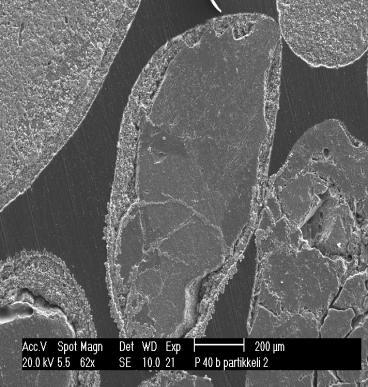
46 304L exposed in the presence of KCl and H 2 O at 600 C for 1hr KCl Fe 2 O 3 K 2 CrO 4 Fe 2 O 3 (Cr,Fe) 2 O 3 Ref: Jonsson et al, Oxidation of metals, 72: (2009)
![Corrosivity of alkali chlorides on two steels Corrosion product layer [µm] 100 80 60 40 20 0 10CrMo9-10 450 500 525 550 T[C] Cr 2 O 3 more protective than Fe 2 O 3 102 186 575 600](/docs-images/93/113981112/images/47-0.jpg "KCl NaCl No salt Corrosion product layer [µm] 100 80 60 40 20 0 NaCl and KCl equally corrosive on the tube surface AISI 347 450 500 525 T[C] 550 575 600 KCl NaCl No salt 47 S.")
47 Corrosivity of alkali chlorides on two steels Corrosion product layer [µm] CrMo T[C] Cr 2 O 3 more protective than Fe 2 O KCl NaCl No salt Corrosion product layer [µm] NaCl and KCl equally corrosive on the tube surface AISI T[C] KCl NaCl No salt 47 S.Enestam
48 Steel composition Grade Category Cr Mo Ni Others Relative price a Typical use (boiler part) 10CrMo9-10 Low alloy Superheaters AISI 347 Standard stainless steel Nb 6.7 Superheaters a May S.Enestam

![layer [μm] 140 120 100 80 60 40 20 0 PbCl2 ZnCl2 KCl](/docs-images/93/113981112/images/49-1.jpg "PbO 250 300 350 400 T[ C] 450 500 550 ZnO No salt 49")
49 Corrosion test: Low alloy steel 10CrMo9-10 The influence of Pb and Zn Corrosion product layer [μm] PbCl2 ZnCl2 KCl PbO T[ C] ZnO No salt 49 S.Enestam

50 INTERNAL Different corrosion types CFB boilers Alkali chloride induced corrosion Erosioncorrosion Heavy metal chloride induced corrosion Dew point corrosion Alkali chloride induced corrosion 50 Date Author Title
51 Dewpoint corrosion Dewpoint of acidic gases 1000 Concentration (ppm) HNO 3 HCl H 2 SO Dewpoint temperature ( C)
52 Dewpoint corrosion Dewpoint corrosion is usually caused by sulfuric acid (H 2 SO 4 ), since it has the highest dewpoint of all the acid gases in the flue gases Dewpoint between C with normal fuels Other acids condense only at temperatures below 80 C The concentration of condensing sulfuric acid depends on the temperature and moisture content Concentration typically between 65% and 75% Temperature close to boiling point Sulfuric acid condensed at dewpoint is very corrosive Alternative corrosion mechanism: corrosion caued by hygroscopic salts such as CaCl 2, ZnCl 2, NH 4 Cl

53 The corrosion rate is influenced by Steel grade Material temperature T mat The corrosivity of the environment T flue gas Flue gas composition Flue gas temperature Solid and/or molten fly ash Deposit composition 53 Metso
54 54 Technical solutions
55 Corrosion -> solutions 1. Superheater material and temperature - Price v.s. life time v.s. efficiency and profitability - Coatings, overlay weld. E.g. Ni based coatings in waste combustion 2. Tube shields most corrosive locations 3. Superheater location 4. Superheater design 5. Fuel mixture: Co-firing or additives 6. Gasification 55 S.Enestam

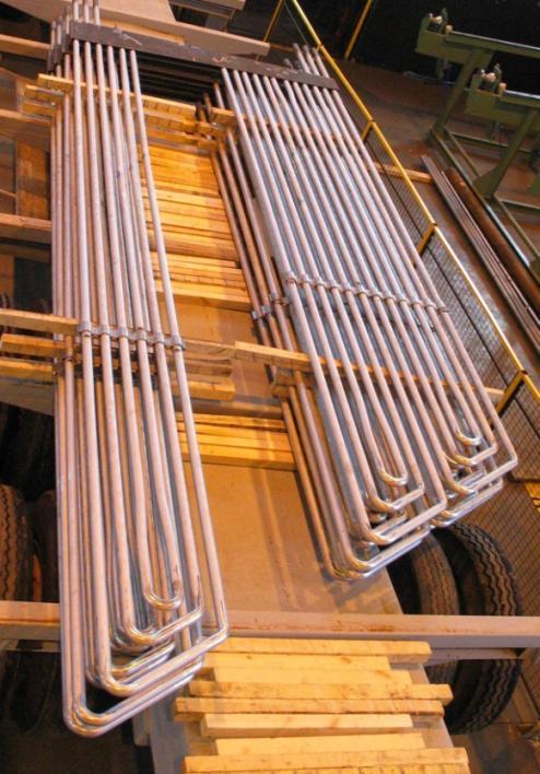
56 Superheaters / REt


57 Water-steam cycle, preassure vessle weight aprox. 600tn, 100km tubing SSH PSH2 PSH1 Boiler bank Eco3 Eco2 Eco1 TSH PAH3 SAH3 SAH2 PAH2 PAH1 SAH /10/20 11
58 HYBEX boiler Bubbling Fluidized Bed (BFB) technology INTERNAL Kymin Voima, Kuusankoski, Finland Steam Fuels 269 MW th 107 kg/s 114 bar 541 C Start-up 2002 Bark, forest residue, sludge, peat, gas, oil
59 HYBEX boiler Bubbling Fluidized Bed (BFB) technology INTERNAL Furnace: Width 12 m Depth 11 m Height 36 m Furnace membrane tubes 26 km Superheater tubes 35 km Economizer tubes 15 km Connection tubes 2 km Weight of pressure parts 1600 ton

 High Cr stainless steel 25-21 N, Nb 10.")
60 Typical boiler materials Increased corrosion resistance Grade Category Cr Mo Ni Others Relative price a Typical use (boiler part) P265GH Non-alloy Eco, furnace, boiler 16Mo3 Low alloy Furnace, bank boiler bank 13CrMo44 Low alloy Superheaters 10CrMo9-10 Low alloy Superheaters X10CrMoVNb9-1 High alloy ferritic 9 1 V, Nb 5.4 Superheaters AISI 347 Standard stainless steel Nb 6.7 Superheaters AISI 310 (Mod c ) High Cr stainless steel N, Nb 10.0 Superheaters a May 2011 c Modified with Nb 60

61 The influence of T fg, T mat and material on corrosion T fg 1100 C T fg 775 C Test materials Air out Removable clad Probe body Air in 61 Date Author Title
 Low alloy steel Probe 2 (WIND ) Low alloy steel 475 C 491 C Probe 2 (WIND) Stainless steel 495 C 4,")

62 The influence of T fg, T mat and material on corrosion Probe 1 (WIND ) Stainless steel 493 C Probe 1 (WIND ) Low alloy steel Probe 2 (WIND ) Low alloy steel 475 C 491 C Probe 2 (WIND) Stainless steel 495 C 4, severe corrosion 533 C T fg 1100 C 4, severe corrosion 533 C 572 C T fg 775 C 572 C 0, no corrosion 0, no corrosion 1, slight corrosion 3, severe corrosion 2, moderate corrosion 4, severe corrosion 62 Date Author Title


63 Calculation of the corrosivity of the environment Material selection based on fuel composition Empirical data data 63 Date Author Title INTERNAL
64 Calculation of the corrosivity of the environment Empirical data data Reference follow-up Laboratory tests Probe tests 64 Date Author Title INTERNAL
65 R&D Expertise SteaMax Plant and fuel specific corrosion prediction SteaMax corrosion evaluations Use - Selection of superheater materials - Optimization of steam temperature - Optimization of fuel mixtures and fuel limits - Evaluation of the corrosivity of fuels and fuel mixtures - Estimation of corrosion rate and superheater life length - Trouble shooting Based on - Composition of fuels and fuel mixtures - Boiler design and superheater placement - Valmet in-house tool for estimating corrosivity - Empirical data from more than 1300 laboratory corrosion tests and more than 45 full scale plants 9 March, 2016 Valmet Author / Title

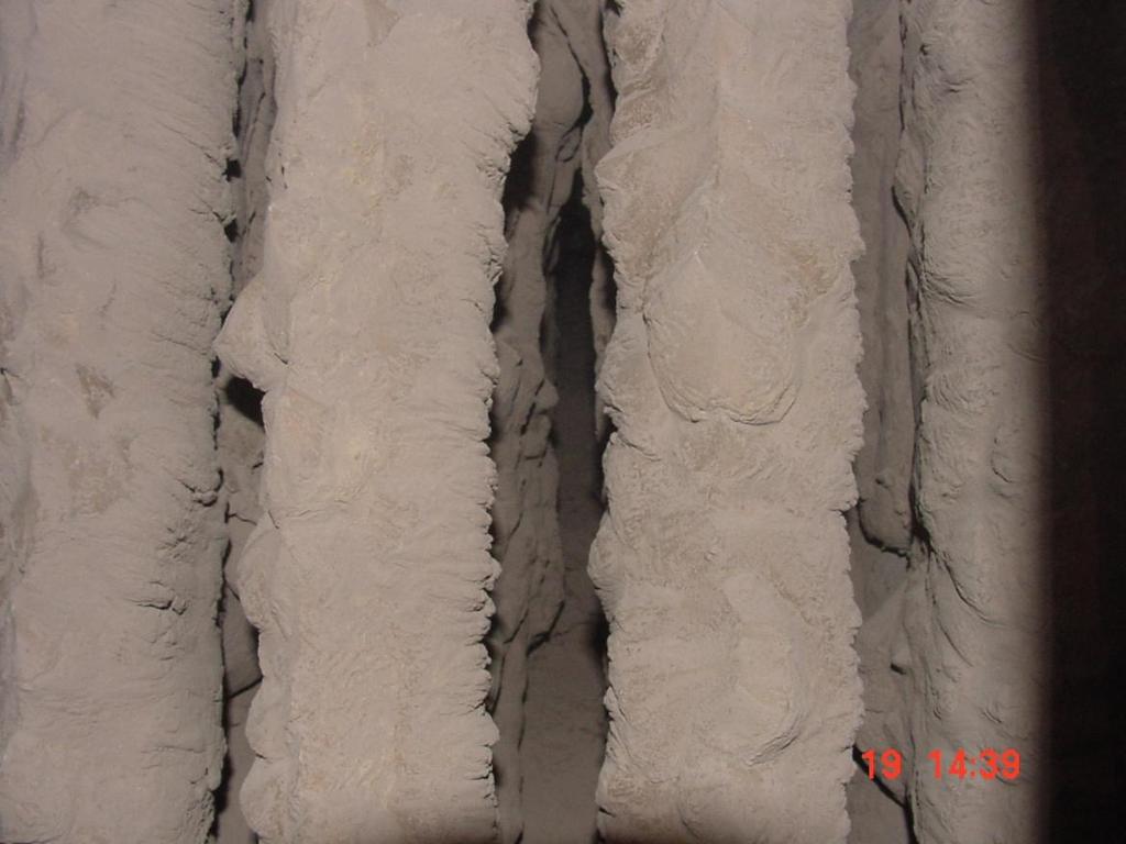
66 Furnace wall corrosion and ower lay welding Typical problem in boilers burning waste and waste wood => Low alloy base material over lay welded with Ni-based alloy 66

67 Corrosion -> solutions 1. Superheater material and temperature - Price v.s. life time v.s. efficiency and profitability - Coatings, overlay weld. E.g. Ni based coatings in waste combustion 2. Tube shields most corrosive locations 3. Superheater location 4. Superheater design 5. Fuel mixture: Co-firing or additives 6. Gasification 67 S.Enestam

68 Tube shields Most corrosive locations 68 Date Author Title INTERNAL

69 Superheater location Reduced concentration of gaseous, corrosive chloride in the vicinity of tube surfaces Empty pass Loop seal superheater 69 Date Author Title
70 Superheater design Reduce probability of contact between tube surface and corrosive chlorides Double tube superheater design => Reduced condensation of corrrosive compounds Single tube design Life length < 1 year Double tube design Life length > 3 years Target surface temperature is determined by the environment (fuels, flue gas temperature, steam temperature,...) Steam Pressure bearing tube Surface temperature is achieved by controlling the tube heat transfer characteristics with additional, coaxial layers 70 Date Author Title
71 Comparison of deposit compositions (XRF) wt-% OLD DESIGN Sample 1 Sample 2 Sample 3 Sample 4 Sample 5 Sample 6 Sample 7 Sample 8 wt-% NEW DESIGN Na2O MgO Al2O3 SiO2 P2O5 SO3 Cl K2O CaO TiO2 CuO ZnO PbO Na2O MgO Al2O3 SiO2 P2O5 SO3 Cl K2O CaO TiO2 CuO ZnO PbO Sample 1 Sample 2 Sample 3 Sample 4 Sample 5 Sample 6 71


72 E.ON Norrköping EfW Plant P14 Steam: Fuels: 75 MW / 6,5 MPa / 470 C MSW, industrial waste, demolition wood, sewage sludge, TDF Norrköping Händelö site # Type Fuel MW th P11 Grate Demolition wood 117 P12 Grate Coal,TDF 125 P13 CFB Bio, TDF 125 P14 CFB Waste 75 72
73 Ways to minimize corrosion Modification of the combustion environment Additives Sulphur Aluminium sulfate Al 2 (SO 4 ) 3 Ferric sulfate Fe 2 (SO 4 ) 3 Ammonium sulfate (NH 4 ) 2 SO 4 Co-combustion Peat Coal Sludge 73 Date Author Title
 3 => 2 Fe 3+ + 3 SO 4 2- Alkali chloride reacts with sulfur trioxide or dioxide")
74 Corrosion management by sulphur addition CorroStop Additives Measures and remedies The sulphate eliminates alkali chlorides in the gas phase and attaches to superheater surfaces forming a protective coat and neutralize the effects of alkalichloride in the process Sulfate decomposes at high temperature: Fe 2 (SO 4 ) 3 => 2 Fe SO 4 2- Alkali chloride reacts with sulfur trioxide or dioxide 2MCl(g,c)+ SO 3 (g)+ H 2 O (g) => M 2 SO 4 (g,c)+ 2 HCl (g) 2MCl(g,c)+ SO 2 (g)+ ½ O 2 (g)+ H 2 O (g) => M 2 SO 4 (g,c)+ 2 HCl (g) where M is Na or K Slow down corrosion of superheaters 74 02/05/2013
75 Fuel mixture - additive Valmet corrosion management Sensor + additive Corrored Analyzer On-line sampling and analysis of the corrosivity of the flue gas Provides information for fuel blend and additive control CorroStop Additives CorroStop liquid solution Aluminiumsulfate Al 2 (SO 4 ) 3 or Ferric sulfate Fe 2 (SO 4 ) % liquid solutions Spraying through nozzles before superheaters CorroStop+ elementary sulphur Sulphur content > 95 % 0,5 3,2 mm granulates Addition to fuel feeding screws 75 02/05/2013
 or S-additive enables the use of low alloy superheater material 76")
76 The influence of fuel mixture on corrosion Corrosive bio fuel mixture requires stainless steel in the hottest superheaters Adding sulphur rich fuel (e.g. peat) or S-additive enables the use of low alloy superheater material 76

 conversion of recycled")

77 Gasification Recycled waste gasification plant for Lahti Energia Oy à à à à Metso delivery: waste gasification process, gas boiler, flue gas cleaning system with auxiliary and automation systems 2 gasification lines: 50 MW of electricity and 90 MW of district heat High-efficiency (gas boiler 121 bar, 540 C) conversion of recycled waste to energy and reduction of fossil fuels Waste is turned into combustible gas, which is cooled, cleaned and combusted in a high-efficiency gas boiler to produce steam for a steam turbine 77
78 Corrosion related plant optimization Efficiency Maximize steam T and p Availability Maintenance costs Investment costs Minimize shut-downs due to corrosion, fouling or bed sintering Minimize the need for tube replacement (=minimize corrosion) Optimize material choice (Good enough material but not too good) 78


79 Corrosion control is a piece of a big puzzle of economics FUEL COST Investment cost Plant efficiency FUEL QUALITY Corrosion control POWER VALUE Maintenance costs Plant availability Plant profitability /S.Enestam
80 Turun Seudun Energiantuotanto CYMIC boiler


81 Turun Seudun Energiantuotanto, Naantali, Finland Turun Seudun Energiantuotanto (TSE) is a utility company owned by local municipalities and Fortum TSE provides district heating for the owner municipalities and electricity Naantali Raisio Turku Kaarina 3/9/

82 82 9 March, 2016 Valmet Author / Title
 technology Steam 144 / 130")

83 Turun Seudun Energiantuotanto, Naantali, Finland CYMIC boiler CYMIC boiler - Circulating Fluidized Bed (CFB) technology Steam 144 / 130 kg/s 164 / 44 bar 555 / 555 C 390 MW th Fuels: Wood biomass, agro biomass, peat, coal, SRF Start-up March, 2016 Valmet Author / Title


84