Instrumentation Process Analyzer Condensed Catalog Regulators, Valves, Flow Controllers, Changeover Systems & Cylinder Connections
|
|
|
- Olivia Ford
- 5 years ago
- Views:
Transcription


1 Instrumentation Process Analyzer Condensed Catalog Regulators, Valves, Flow Controllers, Changeover Systems & Cylinder Connections Veriflo

2 Table of Contents REGULATORS Regulator Porting Guide...3 Single Stage / General Purpose Regulators IR IR4000W IR Dual Stage Regulators IR IR6000W IR High Sensitivity Regulators IR High Flow Regulators HFR HF1200 & HFT High Pressure Regulators APR R XPR Tied Diaphragm Regulators Miniature Regulators MIR Back Pressure Regulators ABP ABP BPR Vaporizing Regulators AVR AVR REGULATORS continued Negative Pressure Regulators NPR NPR VALVES Diaphragm Valves 16 Series NV NV Excess Flow Shut-Off Valve FS Relief Valve VR Check Valve F FLOW CONTROLLERS LC223S SC423XL CHANGEOVER SYSTEMS COSE COSM CYLINDER CONNECTIONS (CGA) 53 Series Series Series Series Series (Seal Enhancers) Series (Washers) Flexible Pigtails Series...48 Express Service Program...50 Contact Information: Visit our website... : 2 Parker Hannifin Corporation Veriflo Division 250 Canal Blvd Richmond, California phone fax veriflo.sales@parker.com For the most complete and up-to-date product information, please visit us at To order Parker Veriflo s complete IPA Product Catalog (# ) Call: Parker Customer Service 800 C PARKER ( ) C-Parker@Parker.com
3 Regulator Porting Guide Standard Configurations Instrumentation In s trum enta tion 2P Instrum entation 4P 4PB 5P In s trum enta tion In s trum enta tion In s trum enta tion 3P 6P Special Configurations In s trum enta tion In s trum enta tion 3SP 4PP 4SP 2 Instrum entation 4 In s trum enta tion 5SP In s trum enta tion In s trum enta tion 5PP In s trum enta tion In s trum enta tion In s trum enta tion 3 3PP In s trum enta tion 3DP 1 Start Point MP When ordering product, port styles are identified by starting at 3 o clock and continuing in the counter clockwise direction. Indicates direction of Flow Placement of Relief Valve, if chosen 6SP 7P (2 Stage Regulators Only) Back Pressure Regulator Configurations (ABP1, ABP3 & BPR50) OUT OUT IN Instrumentation Instrumentation IN Instrumentation IN 2BP IN Instrumentation 3BP IN OUTLET THROUGH BOTTOM 3PP 3PB (Not available with BPR50) (Not available with ABP3) Vaporizing Regulator Configurations (AVR3 & AVR4) 2P 2PL 3PG 3PLG 4PV 4PL 3
4 IR4000 Series Unique patented compression member loads the seal to the body without requiring a threaded nozzle or additional seals. Internally threadless design reduces particle generation. Low internal volume reduces purge times. Cleaned for O 2 service is standard. 316L SS, Single Stage, General Purpose Positive upward and downward stops increase cycle life by preventing over stroking of the diaphragm. Selection of seat materials for media compatibility and temperature applications. Express Service Program available. RANGE TABLE Basic Max Inlet PSIG Model 0.06 C v 0.02 C v 0.15 C v IR IR IR IR IR IR IR Internal Supply Pressure Effect Based upon C v Option 0.02 Cv 0.23 psig/100 psig (0.016 barg/7 barg) 0.06 Cv 0.6 psig/100 psig (0.04 barg/7 barg) 0.15 Cv 1.5 psig/100 psig (0.1 barg/7 barg) Temperature PCTFE PEEK Vespel Based upon seat material choice -40 F to 150 F (-40 C to 66 C) -40 F to 275 F (-40 C to 135 C) -40 F to 500 F (-40 C to 260 C) Dimensional Drawing 4 PORT MOUNTING X Y A 0.69 (17.5mm) 0.88 (22.2mm) B (Std) 0.75 (19.1mm) 0.75 (19.1mm)
5 IR4000 Series continued Build an IR4000 Series Regulator by replacing the numbered symbols with an option from the corresponding tables below. Note: Options in blue/italic type are available for the Express Service Program. Sample: Finished Order: IR40 02 S K 4P B R 580 IR4002SK4P01304BR580 1 Basic Series Range Outlet Gauge 00 = 0-10 psig 0-30 psig 01 = 1-30 psig 0-60 psig 02 = 2-60 psig psig 03 = psig psig 15 = psig psig 04 = psig psig 05 = psig psig 2 Body Material (1) S = 316L Stainless Steel H = Hastelloy C-22 (SST gauges) M = Monel (SST gauges) A = 316L Annealed, 22HRC 3 Flow Capacity = 0.06 Cv (Standard) 1 = 0.02 Cv 2 = 0.15 Cv 4 Seat Material K = PCTFE P = PEEK V = Vespel 5 Porting 2P = 2 Ports - No X required for gauges, Inlet & outlet ports only 3P = 3 Ports - One X for gauge port 4P = 4 Ports - Two X s for gauge ports 4PB = 4 Ports - One X for gauge port 5P = 5 Ports - Two X s for gauge ports Note: Ports may be plugged for NPT threaded product. See Regulator Porting Guide for more information. 6 Outlet Gauge Outlet Gauge Basic Series 03 = 0-30 psig IR4000 OL = 0-60 psig IR = psig IR = psig IR = psig IR = psig IR4005 (Additional ranges available upon request) 7 Inlet Gauge 30 = 3000 psig (Standard) 4 = 400 psig with the 10 psig range 20 = 2000 psig with the 0.15 Cv option 40 = 4000 psig (Additional ranges available upon request) 8 Port Style 2 = 1/8 NPT Female 4 = 1/4 NPT Female 6 = 3/8 NPT Female 4T = 1/4 A-LOK 6T = 3/8 A-LOK (All Gauge ports are 1/4 NPT Female) 9 Port Mounting A = 0.69 (17.5mm) port height w/0.88 (22.2mm) mounting B = 0.75 (19.1mm) port height w/0.75 (19.1mm) mounting (Standard) 10 Optional Features This section can have multiple options B = True Ported Body (no plugs) C = Corrosion Resistant (Stainless Steel Cap) D = Dome Loaded (Not available with G or M options) G = Tamper Proof (Not available with D or M options) M = Metal Knob (Black) (Not available with D or G options) L = PTFE Backup O-Ring (PCTFE and PEEK Seats Only) R = Relief Valve (4PB and 5P Only) S = Self Relieving V = Outlet Valve NOVAS44MF T = Hastelloy Trim (Includes carrier and back-up washer. Option is for Stainless Steel body - Hastelloy Trim is std with Hastelloy and Monel bodies) Note: Panel Mount Option: Order Panel Nut Ring p/n: as a separate line item. Vent Muffler Option: Order Vent Muffler p/n: as a separate line item. 11 CGA# 320, 330, 350, 510, or 660 Do not exceed the rated pressure of the CGA connection. NOTE: (1) Option recommendations for H 2 S-containing fluids Body option H (Hastelloy C-22 ) and A (316L annealed, 22HRC) utilize materials for critical wetted parts that are compliant with NACE standard MR0175/ISO :2003/Cor.2:2005(E), Petroleum and natural gas industries Materials for use in H 2 S-containing environments in oil and gas production, Part 3: Cracking-resistant CRAs (corrosion-resistant alloys) and other alloys. These wetted materials are resistant to cracking in H 2 S - containing fluids, but are not necessarily immune to cracking under all service conditions. The user should consult MR0175/ISO for further guidance. The user should consult Instrumentation Product Division Catalog 4230/4233 for A-Lok Tube Fitting application recommendations. It is the user s responsibility to select materials suitable for the intended service. The following options and accessories are not recommended for H 2 S-containing fluids: - Pressure gauges - V Outlet Valve NOVAS44MF - S Self Relieving - CGA connections - R - Relief valve 5

6 IR4000W Series Unique patented compression member loads the seal to the body without requiring a threaded nozzle or additional seals to atmosphere. Internally threadless design reduces particle generation. Low internal volume reduces purge times. 316L SS, Single Stage, General Purpose Positive upward and downward stops increase cycle life by preventing over stroking of the diaphragm. Selection of seat materials for media compatibility and temperature applications. Cleaned for O 2 service is standard. RANGE TABLE Basic Max Inlet PSIG Model 0.06 C v 0.02 C v 0.15 C v IR4000W IR4001W IR4002W IR4003W IR4004W IR4005W IR4015W Internal Supply Pressure Effect Inboard Test Method < 4 x 10⁻⁸ cc/sec He < 2 x 10⁻⁸ cc/sec He Based upon C v Option 0.02 Cv 0.23 psig/100 psig (0.016 barg/7 barg) 0.06 Cv 0.6 psig/100 psig (0.04 barg/7 barg) 0.15 Cv 1.5 psig/100 psig (0.1 barg/7 barg) Temperature PCTFE PEEK Vespel Based upon seat material choice -40 F to 150 F (-40 C to 66 C) -40 F to 275 F (-40 C to 135 C) -40 F to 500 F (-40 C to 260 C) Dimensional Drawing 6 PORT MOUNTING X Y A (Std) 0.69 (17.5mm) 0.88 (22.2mm) B 0.75 (19.1mm) 0.75 (19.1mm)
7 IR4000W Series continued Build an IR4000W Series Regulator by replacing the numbered symbols with an option from the corresponding tables below Sample: IR40 01 W K 3P X FS MMM A L Finished Order: IR4001WK3PXFSMMMAL 12 1 Basic Series Range Outlet Gauge 00 = 0-10 psig 0-30 psig 01 = 1-30 psig 0-60 psig 02 = 2-60 psig psig 03 = psig psig 15 = psig psig 04 = psig psig 05 = psig psig 2 Body Material W = 316L Stainless Steel 3 Flow Capacity = 0.06 Cv (Standard) 1 = 0.02 Cv 2 = 0.15 Cv 4 Seat Material K = PCTFE P = PEEK V = Vespel 5 Porting 2P = 2 Ports - No X required for gauges, Inlet & outlet ports only 3P = 3 Ports - One X for gauge port 4P = 4 Ports - Two X s for gauge ports 4PB = 4 Ports - One X for gauge port 5P = 5 Ports - Two X s for gauge ports See Regulator Porting Guide for more information 6 Outlet Gauge Outlet Gauge Basic Series 03 = 0-30 psig IR4000W OL = 0-60 psig IR4001W 01 = psig IR4002W 2 = psig IR4003W 4 = psig IR4004W 6 = psig IR4005W (Additional ranges available upon request) 7 Inlet Gauge 30 = 3000 psig (Standard) 4 = 400 psig with the 10 psig range 20 = 2000 psig with the 0.15 Cv option 40 = 4000 psig (Additional ranges available upon request) 8 Port Style 4T = 1/4 A-LOK 6T = 3/8 A-LOK 8T = 1/2 A-LOK FS = 1/4 Face Seal FS8 = 1/2 Face Seal TS = 1/4 Tube Stub TS6 = 3/8 Tube Stub TS8 = 1/2 Tube Stub 9 M F I Port Style = Male = Female = Internal 10 Port Mounting A = 0.69 (17.5mm) port height w/0.88 (22.2mm) mounting (Standard) B = 0.75 (19.1mm) port height w/0.75 (19.1mm) mounting 11 Optional Features This section can have multiple options C = Corrosion Resistant (Stainless Steel Cap) D = Dome Loaded (Not available with G or M options) G = Tamper Proof (Not available with D or M options) M = Metal Knob (Black) (Not available with D or G options) L = PTFE Backup O-Ring (PCTFE and PEEK Seats Only) R = Relief Valve (4PB and 5P Only) S = Self Relieving T = Hastelloy Trim (Includes carrier and back-up washer.) Note: Panel Mount Option: Order Panel Nut Ring p/n: as a separate line item. 12 Industrial CGA# 320, 330, 350, 510, or 660 DISS CGA# 634, 716, 718, 724, or 728 Do not exceed the rated pressure of the CGA connection. 7
8 IR4200 Series Unique patented compression member loads the seal to the body without requiring a threaded nozzle or additional seals to atmosphere. Internally threadless design reduces particle generation. Low internal volume reduces purge times. Brass, Single Stage, General Purpose Positive upward and downward stops increase cycle life by preventing over stroking of the diaphragm. Express Service Program available. Cleaned for O 2 service is standard. RANGE TABLE Basic Max Inlet PSIG Model 0.06 C v 0.02 C v 0.15 C v IR IR IR IR IR IR IR Internal Supply Pressure Effect Based upon C v Option 0.02 Cv 0.23 psig/100 psig (0.016 barg/7 barg) 0.06 Cv 0.6 psig/100 psig (0.04 barg/7 barg) 0.15 Cv 1.5 psig/100 psig (0.1 barg/7 barg) Temperature -40 F to 150 F (-40 C to 66 C) Dimensional Drawing 8 X PORT MOUNTING X Y A 0.69 (17.5mm) 0.88 (22.2mm) B (Std) 0.75 (19.1mm) 0.75 (19.1mm)
9 IR4200 Series continued Build an IR4200 Series Regulator by replacing the numbered symbols with an option from the corresponding tables below. Note: Options in blue/italic type are available for the Express Service Program Sample: IR42 02 B K 4P B S 580 Finished Order: IR4202BK4P01304BS580 1 Basic Series Range Outlet Gauge 00 = 0-10 psig 0-30 psig 01 = 1-30 psig 0-60 psig 02 = 2-60 psig psig 03 = psig psig 15 = psig psig 04 = psig psig 05 = psig psig 2 Body Material B = Brass 3 Flow Capacity = 0.06 Cv (Standard) 1 = 0.02 Cv 2 = 0.15 Cv 4 Seat Material K = PCTFE 5 Porting 2P = 2 Ports - No X required for gauges, Inlet & outlet ports only 3P = 3 Ports - One X for gauge port 4P = 4 Ports - Two X s for gauge ports 4PB = 4 Ports - One X for gauge port 5P = 5 Ports - Two X s for gauge ports Note: Ports may be plugged for NPT threaded product. See Regulator Porting Guide for more information. 6 Outlet Gauge Outlet Gauge Basic Series 03 = 0-30 psig IR4200 OL = 0-60 psig IR = psig IR = psig IR = psig IR = psig IR4205 (Additional ranges available upon request) 7 Inlet Gauge 30 = 3000 psig (Standard) 4 = 400 psig with the 10 psig range 20 = 2000 psig with the 0.15 Cv option 40 = 4000 psig (Additional ranges available upon request) 8 Port Style 2 = 1/8 NPT Female 4 = 1/4 NPT Female 6 = 3/8 NPT Female 4T = 1/4 A-LOK 6T = 3/8 A-LOK (All Gauge ports are 1/4 NPT Female) 9 Port Mounting A = 0.69 (17.5mm) port height w/0.88 (22.2mm) mounting B = 0.75 (19.1mm) port height w/0.75 (19.1mm) mounting (Standard) 10 Optional Features This section can have multiple options B = True Ported Body (no plugs) D = Dome Loaded (Not available with G or M options) G = Tamper Proof (Not available with D or M options) M = Metal Knob (Not available with D or G options) N = Nickel Plate R = Relief Valve (4PB and 5P Only) S = Self Relieving V = Outlet Valve NOVAB44MF Note: Panel Mount Option: Order Panel Nut Ring p/n: as a separate line item. Vent Muffler Option: Order Vent Muffler p/n: as a separate line item. 11 CGA# 320, 330, 350, 510, 580 or 590 Do not exceed the rated pressure of the CGA connection. 9

10 IR6000 Series Unique patented compression member loads the seal to the body without requiring a threaded nozzle or additional seals. 316L SS, Two Stage, General Purpose Internally threadless design reduces particle generation. Low internal volume reduces purge times. Cleaned for O 2 service is standard. Internal Supply Pressure Effect Based upon C v Option 0.02 Cv 0.01 psig/100 psig ( barg/7 barg) 0.06 Cv 0.01 psig/100 psig ( barg/7 barg) 0.15 Cv 0.02 psig/100 psig (0.001 barg/7 barg) Temperature PCTFE PEEK Vespel Based upon seat material choice -40 F to 150 F (-40 C to 66 C) -40 F to 275 F (-40 C to 135 C) -40 F to 500 F (-40 C to 260 C) Positive upward and downward stops increase cycle life by preventing over stroking of the diaphragm. Selection of seat materials for media compatibility and temperature applications. Express Service Program available. Basic Model RANGE TABLE Max Inlet PSIG 0.06 C v 0.02 C v 0.15 C v IR IR IR IR IR IR Dimensional Drawing 10
11 IR6000 Series continued Build an IR6000 Series Regulator by replacing the numbered symbols with an option from the corresponding tables below. Note: Options in blue/italic type are available for the Express Service Program Sample: IR60 02 S K 4P B S 580 Finished Order: IR6002SK4P01304BS580 1 Basic Series Range Outlet Gauge 00 = 0-10 psig 0-30 psig 01 = 1-30 psig 0-60 psig 02 = 2-60 psig psig 03 = psig psig 15 = psig psig 04 = psig psig 2 Body Material S = 316L Stainless Steel H = Hastelloy C-22 (SST gauges) M = Monel (SST gauges) 3 Flow Capacity = 0.06 Cv (Standard) 1 = 0.02 Cv 2 = 0.15 Cv 4 Seat Material K = PCTFE P = PEEK V = Vespel 5 Porting 2P = 2 Ports - No X required for gauges, Inlet & outlet ports only 3P = 3 Ports - One X for gauge port 4P = 4 Ports - Two X s for gauge ports 4PB = 4 Ports - One X for gauge port 5P = 5 Ports - Two X s for gauge ports 6P = 6 Ports - Two X s for gauge ports Note: Ports may be plugged for NPT threaded product. See Regulator Porting Guide for more information. 6 Outlet Gauge Outlet Gauge Basic Series 03 = 0-30 psig IR6000 OL = 0-60 psig IR = psig IR = psig IR = psig IR6004 (Additional ranges available upon request) 7 Inlet Gauge 30 = 3000 psig (Standard) 20 = 2000 psig with the 0.15 Cv option 40 = 4000 psig (Additional ranges available upon request) 8 Port Style 2 = 1/8 NPT Female 4 = 1/4 NPT Female 6 = 3/8 NPT Female 4T = 1/4 A-LOK 6T = 3/8 A-LOK (All Gauge ports are 1/4 NPT Female) 9 Port Mounting B = Standard - No other options 10 Optional Features This section can have multiple options B = True Ported Body (no plugs) C = Corrosion Resistant (Stainless Steel Cap) D = Dome Loaded (Not available with G or M options) G = Tamper Proof (Not available with D or M options) M = Metal Knob (Black) (Not available with D or G options) L = PTFE Backup O-Ring (PCTFE and PEEK Seats Only) R2 = Relief Valve, 2nd Stage () (4PB, 5P and 6P Only) S = Self Relieving V = Outlet Valve NOVAS44MF T = Hastelloy Trim (Includes carrier and back-up washer. Option is for Stainless Steel body - Hastelloy Trim is std with Hastelloy and Monel bodies) Note: Panel Mount Option: Order Panel Nut Ring p/n: as a separate line item. Vent Muffler Option: Order Vent Muffler p/n: as a separate line item. 11 CGA# 320, 330, 350, 510, or 660 Do not exceed the rated pressure of the CGA connection. 11
12 IR6000W Series Unique patented compression member loads the seal to the body without requiring a threaded nozzle or additional seals. Cleaned for O 2 service is standard. 316L SS, Two Stage, General Purpose Internally threadless design reduces particle generation. The low internal volume reduces purge times. Positive upward and downward stops increase cycle life by preventing over stroking of the diaphragm. Captured bonnet allows for safety venting Selection of seat materials for media compatibility and temperature applications. Basic Model RANGE TABLE Max Inlet PSIG 0.06 C v 0.02 C v 0.15 C v IR6000W IR6001W IR6002W IR6003W IR6004W IR6015W Internal Supply Pressure Effect Inboard Test Method 4 X 10⁻⁸ cc/sec He 2 X 10⁻⁸ cc/sec He Based upon C v Option 0.02 Cv 0.01 psig/100 psig ( barg/7 barg) 0.06 Cv 0.01 psig/100 psig ( barg/7 barg) 0.15 Cv 0.02 psig/100 psig (0.001 barg/7 barg) Temperature PCTFE PEEK Vespel Based upon seat material choice -40 F to 150 F (-40 C to 66 C) -40 F to 275 F (-40 C to 135 C) -40 F to 500 F (-40 C to 260 C) Dimensional Drawing 12
13 IR6000W Series continued Build an IR6000W Series Regulator by replacing the numbered symbols with an option from the corresponding tables below Sample: IR60 01 W K 3P X FS MMM B L Finished Order: IR6001WK3PXFSMMMBL 12 1 Basic Series Range Outlet Gauge 00 = 0-10 psig 0-30 psig 01 = 1-30 psig 0-60 psig 02 = 2-60 psig psig 03 = psig psig 15 = psig psig 04 = psig psig 2 Body Material W = 316L Stainless Steel 3 Flow Capacity = 0.06 Cv (Standard) 1 = 0.02 Cv 2 = 0.15 Cv 4 Seat Material K = PCTFE P = PEEK V = Vespel 5 Porting 2P = 2 Ports - No X required for gauges, Inlet & outlet ports only 3P = 3 Ports - One X for gauge port 4P = 4 Ports - Two X s for gauge ports 4PB = 4 Ports - One X for gauge port 5P = 5 Ports - Two X s for gauge ports See Regulator Porting Guide for more information 6 Outlet Gauge Outlet Gauge Basic Series 03 = 0-30 psig IR6000W OL = 0-60 psig IR6001W 01 = psig IR6002W 2 = psig IR6003W 4 = psig IR6004W (Additional ranges available upon request) 7 Inlet Gauge 30 = 3000 psig (Standard) 20 = 2000 psig with the 0.15 Cv option 40 = 4000 psig (Additional ranges available upon request) 8 Port Style 4T = 1/4 A-LOK 6T = 3/8 A-LOK 8T = 1/2 A-LOK FS = 1/4 Face Seal FS8 = 1/2 Face Seal TS = 1/4 Tube Stub TS6 = 3/8 Tube Stub TS8 = 1/2 Tube Stub 9 M F I Port Style = Male = Female = Internal 10 Port Mounting B = Standard (No other options) 11 Optional Features This section can have multiple options C = Corrosion Resistant (Stainless Steel Cap) D = Dome Loaded (Not available with G or M options) G = Tamper Proof (Not available with D or M options) L = PTFE Backup O-Ring (PCTFE and PEEK Seats Only) M = Metal Knob (Not available with D or G options) R2 = Relief Valve (4PB, 5P and 6P Only) S = Self Relieving T = Hastelloy Trim (Includes carrier and back-up washer) Note: Panel Mount Option: Order Panel Nut Ring p/n: as a separate line item. Vent Muffler Option: Order Vent Muffler p/n: as a separate line item. 12 Industrial CGA# 320, 330, 350, 510, or 660 DISS CGA# 634, 716, 718, 724, or 728 Do not exceed the rated pressure of the CGA connection. 13

14 IR6200 Series Unique patented compression member loads the seal to the body without requiring a threaded nozzle or additional seals. Brass, Two Stage, General Purpose Internally threadless design reduces particle generation. The low internal volume reduces purge times. Cleaned for O 2 service is standard. Positive upward and downward stops increase cycle life by preventing over stroking of the diaphragm. Express Service Program available. Basic Model RANGE TABLE Max Inlet PSIG 0.06 C v 0.02 C v 0.15 C v IR IR IR IR IR IR Dimensional Drawing Internal Supply Pressure Effect Based upon C v Option 0.02 Cv 0.01 psig/100 psig ( barg/7 barg) 0.06 Cv 0.01 psig/100 psig ( barg/7 barg) 0.15 Cv 0.02 psig/100 psig ( barg/7 barg) Temperature -40 F to 150 F (-40 C to 66 C) 14
15 IR6200 Series continued Build an IR6200 Series Regulator by replacing the numbered symbols with an option from the corresponding tables below. Note: Options in blue/italic type are available for the Express Service Program Sample: IR62 02 B K 4P B N 580 Finished Order: IR6202BK4P01304BN580 1 Basic Series Range Outlet Gauge 00 = 0-10 psig 0-30 psig 01 = 1-30 psig 0-60 psig 02 = 2-60 psig psig 03 = psig psig 15 = psig psig 04 = psig psig 2 Body Material B = Brass 3 Flow Capacity = 0.06 Cv (Standard) 1 = 0.02 Cv 2 = 0.15 Cv 4 Seat Material K = PCTFE 5 Porting 2P = 2 Ports - No X required for gauges, Inlet & outlet ports only 3P = 3 Ports - One X for gauge port 4P = 4 Ports - Two X s for gauge ports 4PB = 4 Ports - One X for gauge port 5P = 5 Ports - Two X s for gauge ports 6P = 6 Ports - Two X s for gauge ports Note: Ports may be plugged for NPT threaded product. See Regulator Porting Guide for more information. 6 Outlet Gauge Outlet Gauge Basic Series 03 = 0-30 psig IR6200 OL = 0-60 psig IR = psig IR = psig IR = psig IR6204 (Additional ranges available upon request) 7 Inlet Gauge 30 = 3000 psig (Standard) 20 = 2000 psig with the 0.15 Cv option 40 = 4000 psig (Additional ranges available upon request) 8 Port Style 2 = 1/8 NPT Female 4 = 1/4 NPT Female 6 = 3/8 NPT Female 4T = 1/4 A-LOK 6T = 3/8 A-LOK All Gauge ports are 1/4 NPT Female 9 Port Mounting B = Standard Mounting No other options 10 Optional Features This section can have multiple options B = True Ported Body (no plugs) D = Dome Loaded (Not available with G or M options) G = Tamper Proof (Not available with D or M options) M = Metal Knob (Not available with D or G options) N = Nickel Plate R2 = Relief Valve (4PB, 5P and 6P Only) S = Self Relieving V = Outlet Valve NOVAB44MF Note: Panel Mount Option: Order Panel Nut Ring p/n: as a separate line item. Vent Muffler Option: Order Vent Muffler p/n: as a separate line item. 11 CGA# 320, 330, 350, 510, 580 or 590 Do not exceed the rated pressure of the CGA connection. 15

16 IR5000 Series 316L SS, Single Stage, General Purpose, High Sensitivity Unique patented compression member loads the seal to the body without requiring a threaded nozzle or additional seals. Internally threadless design reduces particle generation. Low internal volume reduces purge times. Cleaned for O 2 service is standard. Positive upward and downward stops increase cycle life by preventing over stroking of the diaphragm. Selection of seat materials for media compatibility and temperature applications. Express Service Program available. Basic Model RANGE TABLE Max Inlet PSIG 0.06 C v 0.02 C v 0.15 C v IR IR IR IR IR Dimensional Drawing Internal Supply Pressure Effect Based upon C v Option 0.02 Cv 0.12 psig/100 psig (0.008 barg/7 barg) 0.06 Cv 0.3 psig/100 psig (0.02 barg/7 barg) 0.15 Cv 0.75 psig/100 psig (0.05 barg/7 barg) Temperature Standard IR5000 PCTFE PEEK Vespel Low Pressure IR5000 (P) Based upon seat material choice -40 F to 150 F (-40 C to 66 C) -40 F to 275 F (-40 C to 135 C) -40 F to 500 F (-40 C to 260 C) -40 F to 150 F (-40 C to 66 C) 16
17 IR5000 Series continued Build an IR5000 Series Regulator by replacing the numbered symbols with an option from the corresponding tables below. Note: Options in blue/italic type are available for the Express Service Program Sample: IR50 02 S K 4P B 580 Finished Order: IR5002SK4P01304B580 1 Basic Series Range Outlet Gauge 00 = 0-5 psig 0-30 psig Note: Max inlet pressure is 400 psig 01 = 1-30 psig 0-60 psig 02 = 2-60 psig psig 03 = psig psig 04 = psig psig 2 Body Material S = 316L Stainless Steel H = Hastelloy C-22 Stainless Steel gauges M = Monel Stainless Steel gauges 3 Flow Capacity omit = 0.06 Cv Standard 1 = 0.02 Cv 2 = 0.15 Cv 4 Seat Material K = PCTFE P = PEEK V = Vespel Recommended for Nitrous Oxide (N 2 0) Service 5 Porting 2P = 2 Ports No X required for gauges, Inlet & outlet ports only 3P = 3 Ports One X for gauge port 4P = 4 Ports Two X s for gauge ports 4PB = 4 Ports One X for gauge port Note: Ports may be plugged for NPT threaded product. See Regulator Porting Guide for additional options and port layouts 6 Outlet Gauge Outlet Gauge Basic Series 05 = 0-15 psig IR5000 OL = 0-60 psig IR = psig IR = psig IR = psig IR5004 Additional ranges available upon request 7 Inlet Gauge 30 = 3000 psig Standard 4 = 400 psig with the 5 psig range 20 = 2000 psig with the 0.15 Cv option 40 = 4000 psig Additional ranges available upon request 8 Port Style 2 = 1/8 NPT Female 4 = 1/4 NPT Female 6 = 3/8 NPT Female 8 = 1/2 NPT Female 4T = 1/4 A-LOK 6T = 3/8 A-LOK 8T = 1/2 A-LOK All Gauge ports are 1/4 NPT Female 9 Port Mounting B = 0.75 (19.1 mm) port height w/1.0 (25.4 mm) mounting (Standard) 10 Optional Features This section can have multiple options C = Corrosion Resistant Stainless Steel Cap D = Dome Loaded Not available with G or M options G = Tamper Proof Not available with D or M options L = PTFE Backup O-Ring PCTFE and PEEK Seats Only M = Metal Knob Not available with D or G options R = Relief Valve 4PB Only T = Hastelloy Trim Includes carrier and back-up washer. Option is for Stainless Steel body - Hastelloy Trim is std with Hastelloy and Monel bodies V = Outlet Valve NOVAS44MF P = Low Pressure Only available for 5 psig and 30 psig ranges. Temperature rating: -40 F to 150 F. Max flow rating: 10 slpm Nitrogen. Note: Panel Mount Option: Order Panel Nut Ring p/n: as a separate line item. Vent Muffler Option: Order Vent Muffler p/n: as a separate line item. 11 CGA# 320, 330, 350, 510, 580, 590 or 660 Do not exceed the rated pressure of the CGA connection. Note: 1. Veriflo reserves the right to plug NPT ports. If a true ported body is required, please contact Customer Service. 2. A gas with low molecular weight, such as Hydrogen and Helium, may cause flow vibration. 17
. Large diaphragm for higher sensitivity.")
18 HFR900 Series Self-contained, replaceable valve seat assembly. Over 20 years of proven reliability. Cleaned for O2 Service is standard. Available in Brass or 316L Stainless Steel. 316L SS or Brass, Single Stage, High Flow 1/8 NPT Captured vent port is standard. Large orifice for high flow (up to 500 M). Large diaphragm for higher sensitivity. Dome Load, Relief Valve, Panel Mount and Tamper Proof options available. Maximum Inlet (based upon seat option) Fluorocarbon 500 psig (35 barg) Perfluoroelastomer 200 psig (14 barg) Temperature -40 F to 150 F (-40 C to 66 C) Flow Capacity C v 0.85 Internal Sample: HFR90 0 S 4P K Finished Order: HFR900S4P0364K 18 1 Range 0 = 1-30 psig 1 = 2-75 psig 2 = psig 2 Body Material B = Brass S = 316L Stainless Steel 3 Porting 2P = 2 Ports - No X required for gauges, Inlet & outlet ports only 3P = 3 Ports - One X for gauge port 4P = 4 Ports - Two X s for gauge ports 4PB = 4 Ports - One X for gauge port See Regulator Porting Guide for more information. 4 Outlet Gauge 03 = 0-30 psig OL = 0-60 psig 01 = psig 2 = psig (Additional ranges available upon request) 5 Inlet Gauge 4 = psig 6 = psig (Additional ranges available upon request) 6 Port Style 4 = 1/4 NPT Female 6 = 3/8 NPT Female 8 = 1/2 NPT Female 4T = 1/4 A-LOK 6T = 3/8 A-LOK 8T = 1/2 A-LOK (All Gauge ports are 1/4 NPT Female) 7 Seat Material K = Perfluoroelastomer (FFKM) (200 psig max) V = Fluorocarbon (FKM) 8 (500 psig max) Optional Features This section can have multiple options NP = Nickel Plate (Brass bodies only) PM = Panel Mount (captured vent not available) R = Relief Valve (Fluorocarbon seal - 4PB Only)


19 HF1200 & HFT 1200 Series High inlet pressure with 1.2 Cv to meet a variety of applications. Hastelloy C-22 diaphragm for high corrosion resistance. HFT offers a tied diaphragm for positive shut off. 316L SS, Single Stage, High Flow Large convoluted diaphragm provides stable pressure control. 59% greater effective diaphragm area over competitive products. HFT offers Hastelloy trim for corrosive applications. Maximum Inlet 1,250 psig (86 barg) Temperature PCTFE -40 F to 150 F (-40 C to 66 C) Flow Capacity C v 1.2 Internal Supply Pressure Effect at 70 psig minimum 5.4 psig / 100 psig Sample: HFT12 01 S K 3P 2 8 B Finished Order: HFT1201SK3P28B Basic Series HF12 (Non-Tied Diaphragm) HFT12 (Tied Diaphragm) 2 Pressure Range 00 = 5-50 psig 01 = psig 15 = psig 02 = psig 3 Body Material S = 316L Stainless Steel 4 Seat Material K = PCTFE 5 Porting 2P = 2 Ports No X required for gauges, Inlet & outlet ports only 3P = 3 Ports One X for gauge port 4P = 4 Ports Two X for gauge port 4PB = 4 Ports One X for gauge port See Regulator Porting Guide for additional options and port layouts 6 Outlet Gauge VX = -30 in Hg psig - HFT1200 only. OL = 0-60 psig 01 = psig 2 = psig Additional ranges available upon request 7 Port Style 8 = 1/2 NPT Female 8T = 1/2 A-LOK 12T = 3/4 A-LOK 1/4 NPT Gauge Ports are Standard 8 Place Holder B = Place Holder 9 Options TH = Hastelloy Trim - HFT1200 only. Includes Hastelloy C-22 poppet, seat retainer and Inconel X750 poppet spring 19
20 APR66 Series Thrust bearing allows low actuating torque and precise setability. Cleaned for O2 service is standard. Low friction adjusting screw sleeve provides smooth operation. 316L SS or Brass, Single Stage, High Pressure Piston sensing. Optional self relieving feature allows user to decrease outlet pressure in closed systems. Feature is actuated by turning the adjusting knob counterclockwise. Maximum Inlet 6,000 psig (414 barg) Temperature -40 F to 165 F (-40 C to 74 C) Flow Capacity C v 0.05 Internal Supply Pressure Effect 100-1,000 psig 100-2,000 psig 100-3,000 psig 100-6,000 psig 4 psig/100 psig (0.28 barg/7 barg) 4 psig/100 psig (0.28 barg/7 barg) 4 psig/100 psig (0.28 barg/7 barg) 6 psig/100 psig (0.4 barg/7 barg) Sample: APR66 S 4P 1 X X 4 M 320 Finished Order: APR66S4P1XX4M Body Material B = Nickel Plated Brass S = 316L Stainless Steel 2 Porting 2P = 2 Ports - No X required for gauges, Inlet & outlet ports only 3P = 3 Ports - One X for gauge port 4P = 4 Ports - Two X s for gauge ports See Regulator Porting Guide for more information 3 Pressure Range 1 = psig 2 = psig 3 = psig 4 = psig 4 Outlet Gauge 10 = psig 20 = psig 30 = psig 40 = psig 60 = psig (Additional ranges available upon request) 5 Inlet Gauge 40 = psig 60 = psig (Additional ranges available upon request) 6 Port Style 2 = 1/8 NPT Female 4 = 1/4 NPT Female D = DIN ISO 228/1 - Inlet and Outlet Ports Only MS = MS Inlet and Outlet Ports Only 7 Optional Features This section can have multiple options B = Buna-N Seal M = Metal Knob (Black) SR = Self Relieving For safety purposes, the optional self-relieving feature is not recommended for toxic or flammable gases or liquids. Note: 8 Each unit is standard with a threaded cap and panel mount nut. CGA# 320, 330, 350, 510, 580, 590 or 660* * CGA 660 not available in brass Do not exceed the rated pressure of the CGA connection. (All Gauge ports are 1/4 NPT Female)

21 R800 Series Low actuating torque. Diaphragm sensing regulator. Cleaned for O2 service is standard. Self-contained valve seat assembly. 316L SS, Single Stage, High Pressure Fluid media capabilities: Corrosive and non-corrosive gases. Easily maintained. Maximum inlet of 5,000 psig. Maximum Inlet For Oxygen Temperature 5,000 F ( C) 3,000 psig (206.9 barg) -40 F to 150 F (-40 C to 66 C) Flow Capacity C v 0.02 Internal Supply Pressure Effect 0.5 psig / 100 psig (0.03 barg / 7 barg) Sample: R80 1 S 3P 10 4 Finished Order: R801S3P104 1 Basic Series 0 = psig 1 = psig 2 = psig 2 Body Material B = Brass S = 316L Stainless Steel 3 Porting 2P = 2 Ports - No X required for gauges, Inlet & outlet ports only 3P = 3 Ports - One X for gauge port 4P = 4 Ports - Two X s for gauge ports 5P = 5 Ports - Two X s for gauge ports See Regulator Porting Guide for more information. 4 Outlet Gauge 10 = psig 20 = psig 30 = psig (Additional ranges available upon request) 5 Inlet Gauge 30 = psig 40 = psig 60 = psig (Additional ranges available upon request) 6 Port Style 4 = 1/4 NPT Female (All Gauge ports are 1/4 NPT Female) 7 PM 8 Optional Features This section can have multiple options = Panel Mount Vent Muffler Option: Order Vent Muffler p/n: as a seperate line item. CGA# 320, 330, 350, 510, 580, 590 or 660 Do not exceed the rated pressure of the CGA connection. 21
 Internal Flow Capacity C v 0.")
22 XPR Series Bonnet assembly allows easy changeout. Self relieving adjustment with allen wrench. 316L SS or Brass, Single Stage, High pressure Cleaned for O2 service. Seven range assemblies available. Self relieving allows downstream pressure to be vented through regulator. Stainless Steel Brass Temperature -40 F to 150 F (-40 C to 66 C) Internal Flow Capacity C v Sample: XPR S 15 3P O T Finished Order: XPRS153P20604OT 22 1 Body Material S = 316L Stainless Steel 10,000 psig max inlet B = Brass 6,000 psig max inlet 2 Range Outlet Gauge 5 = psig psig 8 = psig psig 15 = 100-1,500 psig psig 25 = 135-2,500 psig psig 40 = 200-4,000 psig psig 60 = 300-6,000 psig psig 100 = ,000 psig* psig * Available with Stainless Steel body material only 3 Porting 2P = 2 Ports No X required for gauges, Inlet & outlet ports only 3P = 3 Ports One X for gauge port 4P = 4 Ports Two X s for gauge ports 4PB = 4 Ports One X for gauge port See Regulator Porting Guide for additional options and port layouts 4 Outlet Gauge 6 = psig 10 = 0-1,000 psig 20 = 0-2,000 psig 30 = 0-3,000 psig 60 = 0-6,000 psig 100 = 0-10,000 psig Additional ranges available upon request 5 Inlet Gauge 60 = 0-6,000 psig Std 100 = 0-10,000 psig Std for 100 range option Additional ranges available upon request 6 Port Style 2 = 1/8 NPT Female 4 = 1/4 NPT Female 6 = 3/8 NPT Female 1/4 NPT Female Gauge Ports are Standard 7 O-ring Material O = FKM 8 Optional Features This section can have multiple options N = Non-self relieving Q = Nickel Plate Brass body material only T = Tee Bar Handle Note: Panel Mount Option: Order Panel Nut Ring p/n: as a separate line item.

23 735 Series Unique patented compression member loads the seal to body eliminating threads in the wetted area. 316L SS, Two Stage, High Pressure Tied Diaphragm for added safety. Metal-to-metal diaphragm-tobody seal assures high leak integrity. Cleaned for O 2 service is standard. Maximum Inlet 3,500 psig (240 barg) Temperature -40 F to 150 F (-40 C to 65 C) Internal Supply Pressure Effect 0.04 Cv 0.2 psig to100 psig (0.01barg to 7 barg) Sample: S 4P OL 30 4 TH 330 Finished Order: 73530S4POL304TH330 1 Range 30 = 1-30 psig 100 = psig 2 Body Material S = VeriClean 316L Stainless Steel H = Hastelloy C-22 (Includes Hastelloy C-22 body, diaphragm, compresson member, poppet and Inconel spring.) 3 Porting 2P = 2 Ports - No X required for gauges, Inlet & outlet ports only 3P = 3 Ports - One X for gauge port 4P = 4 Ports - Two X s for gauge ports 5P = 5 Ports - Two X s for gauge ports 7P = 7 Ports - Two X s for gauge ports See Regulator Porting Guide for more information. 4 Outlet Gauge 03 = 0-30 psig OL = 0-60 psig 01 = psig Additional ranges available upon request 5 Inlet Gauge 30 = 3000 psig 4 = 400 psig 40 = 4000 psig Additional ranges available upon request 6 Port Style 4 = 1/4 NPT Female Note: All Gauge ports are 1/4 NPT Female 7 Optional Features This section can have multiple options PM = Panel Mount R2 = Relief Valve (5P Only) TH = Hastelloy Trim Available on Stainless Steel body, only. Includes Hastelloy C-22 diaphragm, compresson member, poppet and screen with an Inconel spring. VESP = Vespel Seat (Recommended for N 2 O Service) 8 CGA# (Specify CGA No.) 320, 330, 350, 510, 580, 590, or 660 Do not exceed the rated pressure of the CGA connection. 23
24 959 Series Tied Diaphragm for added safety. Unique patented compression member loads seal to body without requiring a threaded nozzle or additional seals to atmosphere. 316L SS, Single Stage, High Pressure Metal-to-metal diaphragmto-body seal assures high leak integrity. Cleaned for O2 service is standard. Adjustment range spring may be replaced without breaking diaphragm seal to body and exposing the wetted area to contamination. Maximum Inlet Cv 0.04 Cv 0.2 Outlet Options Temperature based on C v Option 3,500 psig (240 barg) 1,250 psig (86 barg) 1-30 psig (2 barg) psig (7 barg) psig (10.3 barg) -40 F to 150 F (-40 C to 65 C) Flow Capacity Cv Options C v 0.04 (std) or C v 0.2 Internal Supply Pressure Effect Cv 0.04 Cv psig/100 psig 1.5 psig/100 psig Sample: S 4P OL 30 4 TH Finished Order: 95930S4POL304TH 24 1 Range 30 = 1-30 psig 100 = psig 150 = psig 2 Body Material S = 316L Stainless Steel H = Hastelloy C-22 Includes Hastelloy C-22 body, diaphragm, compresson member, poppet and Inconel spring 3 Porting 2P = 2 Ports No X required for gauges, inlet & outlet ports only 3P = 3 Ports One X for gauge port 4P = 4 Ports Two X s for gauge ports 4PB = 4 Ports One X for gauge port 5P = 5 Ports Two X s for gauge ports 6P = 6 Ports Two X s for gauge ports See Regulator Porting Guide for additional options and port layouts 4 Outlet Gauge 03 = 0-30 psig OL = 0-60 psig 01 = psig 2 = psig Additional ranges available upon request 5 Inlet Gauge 2 = psig 6 = psig 10 = psig 20 = psig 30 = psig 40 = psig Additional ranges available upon request 6 Port Style 4 = 1/4 NPT Female All Gauge Ports are 1/4 NPT Female 7 Optional Features This section can have multiple options 2 = 0.2 Cv DO = Dome Loaded PM = Panel Mount R = Relief Valve 4PB, 5P and 6P Only TH = Hastelloy Trim Available on Stainless Steel body, only. Includes Hastelloy C-22 diaphragm, compresson member, poppet and screen with an Inconel spring VESP = Vespel Seat Recommended for N 2 O Service
 Temperature -40 F to 150 F (-40 C to 66 C) Flow Capacity C v 0.02 Internal Supply Pressure Effect 0.6 psig/100 psig (0.03barg/6.")
25 MIR700 Series Precise flexing Hastelloy C-22 diaphragm. Cleaned for O2 service is standard. Proven valve seat assembly. 316L SS or Brass, Single Stage, Compact Regulator Low internal volume. Machined from solid bar stock. Maximum Inlet 3,000 psig (207 barg) Temperature -40 F to 150 F (-40 C to 66 C) Flow Capacity C v 0.02 Internal Supply Pressure Effect 0.6 psig/100 psig (0.03barg/6.80 barg) Sample: MIR B 4P Finished Order: MIR70030B4P Pressure Setting 15 = 1-15 psig 30 = 2-30 psig 100 = psig 200 = psig 2 Body Material B = Nickel Plated Brass S = 316L Stainless Steel 3 Porting 2P = 2 Ports 3P = 3 Ports 4P = 4 Ports 4PB = 4 Ports See Regulator Porting Guide for more information. 4 Outlet Gauge 03 = 0-30 psig 01 = psig 2 = psig (Additional ranges available upon request) 5 Inlet Gauge 01 = psig 2 = psig 6 = psig 10 = psig 20 = psig 30 = psig 40 = psig (Additional ranges available upon request) 6 Port Style 2 = 1/8 NPT Female 4 = 1/4 NPT Female 7 Optional Features This section can have multiple options FTD = Fairprene Diaphragm M = Miniature Instrument Knob MH = Mounting Holes PM = Panel Mount R = Relief Valve (4PB Only) 8 CGA# 320, 330, 350, 510, or 660 Do not exceed the rated pressure of the CGA connection. 25
26 ABP1 Series Standard Hastelloy C-22 diaphragm for superior strength and corrosion resistance. Convoluted diaphragm provides outlet pressure stability with changes in flow. 316L SS, Back Pressure Regulator Integral diaphragm stop provides an additional safety measure. Cleaned for O2 service is standard. Express Service Program is available. Max. Control Pressure Max. Temperature of Flow Media psig (35 barg) -15 F to 400 F (26 C to 204 C) Note: Metal Knob required for high temperature applications Flow Capacity Cv Internal 0.3 C v (std), 0.1 C v or 0.06 C v Note: Options in blue/italic type are available for the Express Service Program. Sample: Finished Order: ABP1 S T 3 3BP 2 4 ABP1ST33BP Body Material S = 316L Stainless Steel H = Hastelloy C-22 M = Monel 2 Seat Material T = PTFE V = Fluorocarbon Elastomer (FKM) K = Perfluoroelastomer (FFKM) 3 Pressure Range Range Gauge 1 = 1-25 psig psig 2 = 2-50 psig OL 0-60 psig 3 = psig psig 4 = psig psig 5 = psig psig 4 Porting (Refer to Porting Guide on Page 3) 2BP = 2 Ports - No X required for gauges, Inlet & outlet ports only, 3BP = 3 Ports - One X for gauge port 3PB = 3 Ports - One X for gauge port (outlet though bottom) 3PP = 3 Ports - One X for gauge ports 5 Inlet Gauge 03 = 0-30 psig OL = 0-60 psig 2 = psig 4 = psig 6 = psig (Additional ranges available upon request) 6 Port Style 2 = 1/8 NPT Female 4 = 1/4 NPT Female (All Gauge ports are 1/4 NPT Female) 7 Optional Features This section can have multiple options DO= Dome Loaded (Not available with M option) M = Metal Knob (Black) (Not available with DO options) 06 = 0.06 Cv 1 = 0.1 Cv Note: Panel Mount Option: Order Panel Nut Ring p/n: as a separate line item. Vent Muffler Option: Order Vent Muffler p/n: as a separate line item.
27 ABP3 Series Standard Hastelloy C-22 diaphragm for superior strength and corrosion resistance. Cleaned for O2 service is standard. Convoluted diaphragm provides outlet pressure stability with changes in flow. 316L SS, Back Pressure Regulator Integral diaphragm stop provides an additional safety measure. Express Service Program is available. Max. Control Pressure Max. Temperature of Flow Media 2-60 psig ( barg) -15 F to 400 F (26 C to 204 C) Note: Metal Knob required for high temperature applications Flow Capacity Cv Internal 0.3 C v (std), 0.1 C v or 0.06 C v Note: Options in blue/italic type are available for the Express Service Program. Sample: Finished Order: ABP3 S T 3 3BP 01 4 ABP3ST33BP014 1 Body Material S = 316L Stainless Steel H = Hastelloy C-22 2 Seat Material T = PTFE V = Fluorocarbon Elastomer (FKM) K = Perfluoroelastomer (FFKM) 3 Pressure Range Range Gauge 1 = 1-5 psig psig 2 = 1-30 psig OL 0-60 psig 3 = 2-60 psig psig 4 Porting (Refer to Porting Guide on Page 3) 2BP = 2 Ports - No X required for gauges, Inlet & outlet ports only. 3BP = 3 Ports - One X for gauge port 3PP = 3 Ports - One X for gauge port 5 Inlet Gauge 05 = 0-15 psig OL = 0-60 psig 01 = psig (Additional ranges available upon request) 6 Port Style 2 = 1/8 NPT Female 4 = 1/4 NPT Female (All Gauge ports are 1/4 NPT Female) 7 Optional Features This section can have multiple options DO= Dome Loaded (Not available with M option) M = Metal Knob (Black) (Not available with DO options, required for higher temperatures) 06 = 0.06 Cv 1 = 0.1 Cv Note: Panel Mount Option: Order Panel Nut Ring p/n: as a separate line item. Vent Muffler Option: Order Vent Muffler p/n: as a separate line item. 27

28 BPR50 Series 316L Stainless Steel construction. Cleaned for O2 service is standard. Gas or Liquid Service. Simple construction makes maintenance easy. 316L SS, High Pressure, Back Pressure Regulator Panel mount option is available. Adjustable pressures from 100 to 1,200 psig and 200 to 2,000 psig. Flow Coefficient of 0.45 Cv. Control Pressure Temperature 100-1,200 psig (7-83 barg) 200-2,000 psig ( barg) -40 F to 150 F (-40 C to 66 C) Internal Sample: BPR50 S 3PB 1 BH PM Finished Order: BPR50S3PB1BM 1 Body Material S = 316L Stainless Steel 2 Porting (Refer to Porting Guide on Page 3) 2PB = 2 Ports - Outlet through bottom 3BP = 3 Ports 3PB = 3 Ports - Outlet through bottom 3 Adjustment Range 1 = psig 2 = psig 4 Actuation Devices BH = T Bar Handle Omit = Broach Stem (Standard) 5 Optional Features This section can have multiple options K = Perfluoroelastomer (FFKM) O-ring with PCTFE Seal PM = Panel Mount 28

29 AVR3 Series Steam Heated, Pressure Reducing, Vaporizing Regulator Ultra low internal volume. Cleaned for O2 service is standard. Convoluted Hastelloy C-22 diaphragm for superior strength and corrosion resistance provides outlet pressure stability with changes in flow. Integral diaphragm stop provides additional measure of safety. Field serviceable heat transfer element. Express Service Program is available. Flow Capacity C v 0.06 Nominal Internal Maximum Inlet Temperatures PCTFE PEEK Vespel Maximum Steam Supply 3,500 psig (241 barg) or 250 psig (17.2 barg) for 10 psig range based upon seat option 150 F (66 C) 275 F (135 C) 500 F (260 C) 600 psig, 500 F (41 barg, 260 C) Note: Options in blue/italic type are available for the Express Service Program. Sample: Finished Order: AVR3 S K 1 X 3PG AVR3SK1X3PG 1 Body Material S = 316L Stainless Steel H = Hastelloy C-22 M = Monel 2 Seat Material K = PCTFE P = PEEK V = Vespel 3 Pressure Range 0 = 0-10 psig (max inlet 250 psig) 1 = 1-30 psig 2 = 2-60 psig 3 = psig 4 = psig 5 = psig 4 Outlet Gauge 03 = 0-30 psig OL = 0-60 psig 01 = psig 4 = psig 6 = psig X = No Gauge 5 Porting Configuration (Refer to Porting Guide on Page 3) blank = 2 Port 3PG = 3 Port - Relief Valve or Gauge Port 4PV = 4 Port - Relief Valve and Gauge Port 2PL = 2 Port - Reverse Entry 3PLG = 3 Port - Reverse Entry Relief Valve or Gauge Port 4PL = 4 Port - Reverse Entry Relief Valve and Gauge Port 6 Optional Features RV = Relief Valve Note: Panel Mount Option: Order Panel Nut Ring P/N as a separate line item. Note: Additional options are available. Contact Veriflo for more information 29

 or 250 psig (17.")
30 AVR4 Series Flow Capacity Internal C v 0.06 Nominal Ultra low internal volume. CSA, CE-ATEX certified. Cleaned for O2 service is standard. Convoluted Hastelloy C-22 diaphragm for superior strength and corrosion resistance provides outlet pressure stability with changes in flow. Field serviceable heat transfer element. Electrically Heated, Pressure Reducing, Vaporizing Regulator Maximum Inlet Temperatures PCTFE PEEK Vespel Ambient Temperature TCO (Thermal cut-out) is standard for all heat ranges. Integral diaphragm stop provides additional measure of safety. Express Service Program is available. 3,500 psig (241 barg) or 250 psig (17.2 barg) for 10 psig range based upon seat option 150 F (66 C) 275 F (135 C) 500 F (260 C) -4 F to +104 F (-20 C to +40 C) Note: Options in blue/italic type are available for the Express Service Program Sample: AVR4 S K D L X 3PG RV Finished Order: AVR4SK1120DLX3PGRV 30 1 Body Material S = 316L Stainless Steel H = Hastelloy C-22 M = Monel 2 Seat Material K = PCTFE P = PEEK V = Vespel 3 Pressure Range 0 = 0-10 psig (max inlet 250 psig) 1 = 1-30 psig 2 = 2-60 psig 3 = psig 4 = psig 5 = psig 4 Voltage 120 = 120V 240 = 240V 5 Heater Wattage A = 40 C = 100 D = 150 E = L H Temperature Controller = 75 F to 220 F (24 C C) = 220 F to 380 F (104 C C) 7 Outlet Gauge 03 = 0-30 psig OL = 0-60 psig 01 = psig 4 = psig 6 = psig 8 Porting Configuration (Refer to Porting Guide on Page 3) blank = 2 Port 2PL 3PG = 2 Port - Reverse Entry = 3 Port - Relief Valve or Gauge Port 3PLG = 3 Port - Reverse Entry Relief Valve or Gauge Port 4PV = 4 Port - Relief Valve and Gauge Port 4PL = 4 Port - Reverse Entry Relief Valve and Gauge Port Note: High Pressure port standard is 1/8 NPT Female. 1/4 NPT Female on auxillary outlet ports. 9 Optional Features RV = Relief Valve SL1 = SilcoNert 1000 Note: Panel Mount Option: Order Panel Nut Ring P/N as a separate line item.
31 NPR4100 Series Unique patented compression member loads the seal to the body without requiring a threaded nozzle or additional seals. Internally threadless design reduces particle generation. The low internal volume reduces purge times. Cleaned for O2 service is standard. 316L SS, Negative Pressure Regulator Positive upward and downward stops increase cycle life by preventing over stroking of the diaphragm. Selection of seat materials for media compatibility and temperature applications. Unique carrier design disperses gas uniformly through the regulator to improve purging. Internal Maximum Inlet Temperature PCTFE PEEK * 250 psig (17 barg) Based upon seat material choice -40 F to 150 F (-40 C to 66 C) -40 F to 275 F (-40 C to 135 C) Vespel * -40 F to 500 F (-40 C to 260 C) *Not available for Brass Bodies * Sample: NPR410 0 S K 4P V3 V1 4 B C Finished Order: NPR4100SK4PV3V14BC 1 Pressure Range 0 = -26 in Hg - 10 psig 2 Body Material S = 316L Stainless Steel B = Brass H = Hastelloy C-22 SST gauges M = Monel SST gauges 3 Flow Capacity omit = 0.06 Cv (Standard) 1 = 0.02 Cv 2 = 0.15 Cv 4 Seat Material K = PCTFE P = PEEK V = Vespel Recommended for Nitrous Oxide (N20) Service 5 Porting 2P = 2 Ports No X required for gauges, Inlet & outlet ports only 3P = 3 Ports One X for gauge port 4P = 4 Ports Two X s for gauge ports 4PB = 4 Ports One X for gauge port Note: Ports may be plugged for NPT threaded product. See Regulator Porting Guide for additional options and port layouts 6 Outlet Gauge V3 = -30 in Hg 0-30 psig 7 Inlet Gauge V3 = -30 in Hg 0-30 psig V1 = -30 in Hg psig 2 = psig 4 = psig 8 Port Style 2 = 1/8 NPT Female 4 = 1/4 NPT Female 6 = 3/8 NPT Female 4T = 1/4 A-LOK 6T = 3/8 A-LOK 8T = 1/2 A-LOK All Gauge ports are 1/4 NPT Female 9 B 10 Port Mounting = 0.75 port height w/0.75 mounting hole pattern Optional Features This section can have multiple options B = True Ported Body no plugs C = Corrosion Resistant Stainless Steel Cap D = Dome Loaded Not available with G or M options G = Tamper Proof Not available with D or M options L = PTFE Backup O-Ring PCTFE and PEEK Seats Only M = Metal Knob (White) Not available with D or G options N = Nickel Plate Brass bodies only R = Relief Valve 4PB Only T = Hastelloy Trim Includes carrier and back-up washer. Option is for Stainless Steel body - Hastelloy Trim is std with Hastelloy and Monel bodies V = Outlet Valve NOVAS44MF or NOVAB44MF for Brass Body Note: Panel Mount Option: Order Panel Nut Ring p/n: as a separate line item. Vent Muffler Option: Order Vent Muffler p/n: as a separate line item. 11 CGA# 320, 330, 350, 510, 580, or 590 Do not exceed the rated pressure of the CGA connection. 31

32 NPR959 Series Tied Diaphragm for added safety. Unique patented compression member loads seal to body without requiring a threaded nozzle or additional seals to atmosphere. 316L SS, Negative Pressure Regulator Metal-to-metal diaphragmto-body seal assures high leak integrity. Cleaned for O2 service is standard. Adjustment range spring may be replaced without breaking diaphragm seal to body and exposing the wetted area to contamination. Maximum Inlet based on C v Option Cv ,500 psig (240 barg) Cv 0.2 1,250 psig (86 barg) Outlet Option -25 in Hg psig Temperature -40 F to 150 F (-40 C to 65 C) Flow Capacity Cv Options C v 0.04 (std) or C v 0.2 Internal Supply Pressure Effect Cv 0.04 Cv psig/100 psig 1.5 psig/100 psig Sample: S 4P OL 30 4 TH Finished Order: 95930S4POL304TH 32 1 Range NPR959 = -25 in Hg 0-30 psig 2 Body Material S = 316L Stainless Steel H = Hastelloy C-22 Includes Hastelloy C-22 body, diaphragm, compresson member, poppet and Inconel spring 3 Porting 2P = 2 Ports No X required for gauges, inlet & outlet ports only 3P = 3 Ports One X for gauge port 4P = 4 Ports Two X s for gauge ports 4PB = 4 Ports One X for gauge port 5P = 5 Ports Two X s for gauge ports 6P = 6 Ports Two X s for gauge ports See Regulator Porting Guide for additional options and port layouts 4 Outlet Gauge V3 = -30 in Hg 0-30 psig V1 = -30 in Hg psig Additional ranges available upon request 5 Inlet Gauge V3 = -30 in Hg 0-30 psig V1 = -30 in Hg psig Additional ranges available upon request 6 Port Style 4 = 1/4 NPT Female All Gauge Ports are 1/4 NPT Female 7 Optional Features This section can have multiple options 2 = 0.2 Cv DO = Dome Loaded PM = Panel Mount R = Relief Valve 4PB, 5P and 6P Only TH = Hastelloy Trim Available on Stainless Steel body, only. Includes Hastelloy C-22 diaphragm, compresson member, poppet and screen with an Inconel spring VESP = Vespel Seat Recommended for N 2 O Service

33 16 Series Metal diaphragm sealed. Spring type design. Minimal particle generation. 316L SS, High Pressure, High Flow Valve High cycle life. Cleaned for O2 service. 3,000 psig for both manual and pneumatic styles. Pressure Rating Actuation Pressure Max Differential Back Pressure Vacuum to 3,000 psig 70 psig min to 125 psig max 200 psid Temperature -65 F to 150 F (-54 C to 66 C) Flow Capacity C v 0.3 Internal (NPT Threaded) Internal (Welded) 2 x 10⁻⁸ scc/sec He (Outboard Test Method) 2 x 10⁻⁹ scc/sec He (Outboard Test Method) Sample: VM VM -PI Finished Order: VMVM-PI 1 Basic Series 16- = Handwheel = Pnuematic 2 Port Size 88 = 1/2 Inlet/Outlet 4 C F M TW VF VM Inlet Connection = A-LOK = 1/2 NPT Female = 1/2 NPT Male = Tube Stub = VacuSeal Female = VacuSeal Male 6 Optional Features -PI = Vespel Seat Material PM = Panel Mount Rings 3 Body Material 2 = 316L Stainless Steel 5 C F M TW VF VM Outlet Connection = A-LOK = 1/2 NPT Female = 1/2 NPT Male = Tube Stub = VacuSeal Female = VacuSeal Male 33

 vacuum to 250 psig (17.24 barg) vacuum to 500 psig (34.47 barg) vacuum to 250 psig (17.24 barg) 50 psig min. (3.45 barg) at 500 psig inlet 65 psig min. (4.48 barg) 75 psig min. (5.")
 -40 F to 150 F (-40 C to 66 C) 1 2 3 4 Sample: NV17 AOP2 S 44MF VESP Finished Order: NV17AOP2S44MFVESP 34 1 Type AOPNO = Air Operated, Normally Open AOP1 = Air Operated, Normally")

34 NV17 Series Internally threadless and springless. 316L SS, High Pressure, Compact Size Valve Metal-to-metal seal to atmosphere. High cycle life. Compact size. Cleaned for oxygen service. Low actuation pressure for AOP configuration. Tamper resistant bonnet design. Low internal volume. Flow Capacity Standard C v 0.17 Lever C v 0.15 Internal Operating Pressure Manual AOPNO AOP1 AOP2 AOP3 Actuation Pressure AOPNO AOP1 AOP2 AOP3 Temperature vacuum to 3500 psig (241 barg) vacuum to 500 psig (34.47 barg) vacuum to 250 psig (17.24 barg) vacuum to 500 psig (34.47 barg) vacuum to 250 psig (17.24 barg) 50 psig min. (3.45 barg) at 500 psig inlet 65 psig min. (4.48 barg) 75 psig min. (5.17 barg) 40 psig min. (2.75 barg) -40 F to 150 F (-40 C to 66 C) Sample: NV17 AOP2 S 44MF VESP Finished Order: NV17AOP2S44MFVESP 34 1 Type AOPNO = Air Operated, Normally Open AOP1 = Air Operated, Normally Closed AOP2 = Air Operated, Normally Closed AOP3 = Air Operated, Normally Closed I = Indicating Handwheel L = Lever S = Spin handwheel M = Mini Lever 2 Material S = Stainless Steel B = Brass 3 Connections 44TM = 1/4 Compression in and 1/4 NPT male out 44MT = 1/4 NPT in and 1/4 Compression out 44TT = 1/4 Compression in 44FF and out = 1/4 Female NPT in and out 44MM = 1/4 Male NPT in and out 44MF = 1/4 Male NPT in and Female NPT out 4 Optional Features This section can have multiple options PEEK = PEEK TM Seat VESP = Vespel Seat Note: Vespel seat material is recommended for Nitrous Oxide (N 2 O) service. Compression ends include nuts and ferrules)

35 NV55 Series Internally threadless and springless. High cycle life. Compact size. Positive, consistent shut off. Metal-to-metal seal to atmosphere. 316L SS, High Flow, Compact Size Valve Cleaned for O2 service. Ideal for high flow applications. Fully functional from vacuum to 125 psig for AOP valves and 250 psig for manual valves. Operating Pressures Manual vacuum to 250 psig (17.2 barg) AOP vacuum to 125 psig (8.6 barg) Actuator Pressure psig ( barg) Temperature -15 F to 150 F (-26 C to 66 C) Flow Capacity AOP versions, Indicator Knob and Handwheel C v 0.55 Lever versions C v 0.48 Internal Sample: NV55 LL S 44MM VESP Finished Order: NV55LLS 44MMVESP 1 Type AOPNC = Air Operated, Low Pressure, Normally Closed AOPNO = Air Operated, Low Pressure, Normally Open I = Indicator Knob L = Lever LL = Locking Lever M = Mini Lever S = Spin Handwheel 2 Material S = Stainless Steel 3 Connections 4 44MM = 1/4 Male NPT In & Out 44FF = 1/4 Female NPT In & Out PM 44TT = 1/4 Compression In & Out 66MM = 3/8 Male NPT In & Out 66FF = 3/8 Female NPT In & Out 66TT = 3/8 Compression In & Out 88MM = 1/2 Male NPT In & Out 88FF = 1/2 Female NPT In & Out 88TT = 1/2 Compression In & Out Compression ends include nuts and ferrules Optional Features This section can have multiple options = Panel Mount (not available with Indicator Knob (I) or AOP units (AOPNC or AOPNO) PEEK = PEEK TM Seat (not available with VESP option) VESP = Vespel Seat (not available with PEEK option) Note: Vespel seat material is recommended for Nitrous Oxide (N 2 O) service. 35
 or Auto (Shut off).")
36 FS190 Series Offered with 6 different pressure/flow limits. Differential pressure that is created is not affected by mounting orientation (nonattitude sensitive). Cleaned for O2 service. 316L SS, Excess Flow Shut-Off Valve Actuating knob designed to manually operate valve and clearly indicate relative operating position - Open (Reset) or Auto (Shut off). Pneumatic actuator available to reset the valve remotely. Temperature Supply Pressure A - D Flow Limits: E - F Flow Limits: Differential Pressure Sample: Finished Order: -10 F to 150 F (-23 C to 66 C) Based upon Flow Limit Setting 10 psig to 3,500 psig (0.7 barg to 241 barg) 20 psig to 3,500 psig (1.4 barg to 241 barg) 5 psig or 12 psig (0.3 barg or 0.8 barg) FS190 S A FSFM AOP FS190SAFSFMAOP 36 1 Material S = 316L Stainless Steel 2 Flow Limit Setting Nominal Flow Limit at: 1000 psig Inlet 30 psig Inlet A = 4.8 SM 0.4 SM B = 9.1 SM 1.7 SM C = 21.8 SM 3.9 SM D = 39.5 SM 9.0 SM E = 72.3 SM 14.4 SM F = SM 22.5 SM 3 Connection (Inlet & Outlet) P = 1/4 NPTF FSMM = 1/4 FS Male In, Male Out FSFF = 1/4 FS Female In, Female Out FSFM = 1/4 FS Female In, Male Out FSMF = 1/4 FS Male In, Female Out TS = 1/4 Welded Tube Stubs 4 Optional Features This section can have multiple options AOP = Air Operated EX = 10 Ra microinch Finish (not available with P Connection Option) TH = Hastelloy C-22 Trim Internals (Includes compression member, poppet, spring and orifice) 3.46 = FLV 110 Dimensional Replacement (3.46 end-to-end dimensions) 3.70 = FLV 120 Dimensional Replacement (3.70 end-to-end dimensions) 5.25 = 5.25 end-to-end dimensions 5.75 = 5.75 end-to-end dimensions

37 VR7 Series The VR7 Series is an economical relief valve designed to vent excess pressure from a regulator should a minor seat leak occur. This valve is recommended for use with regulators to protect the regulator and outlet pressure gauge and is not intended for applications where repeated or frequent venting is required. 316L SS or Brass, Pressure Relief Valve Choice of seal materials for system compatibility. Hex body provides wrench flats. Available with a variety of connections. Cleaned for O2 service. Note: The VR7 SHOULD ONLY be used to protect Article 3, Paragraph 3 category equipment as defined in Pressure Equipment Directive 97/23/EC Dated 29, May Flow Capacity Maximum Pressure Temperature Adjustable Ranges 0.37 C v 750 psig (52 barg) -30 F to 400 F (-35 C to 204 C) psig ( barg) psig (1.4-7 barg) psig (7-17 barg) psig (17-34 barg) Sample: VR7 44MF 1 S V Finished Order: VR744MF1SV 1 Connection (Inlet & Outlet) 2 Adjustable Range 3 44MF = 1/4 NPTM x 1/4 NPTF 1 = psig 4FSF = 1/4 FS Female x 1/4 NPTF 2 = psig (available for Stainless Steel body Only) 4FSM = 1/4 FS Male x 1/4 NPTF 3 = psig (available for Stainless Steel body Only) 4 = psig NOTE: After relieving, service is required. Body Material S = 316L Stainless Steel B = Brass 4 Seal K = FFKM V = FKM 37
 version for Ultra High Purity applications available.")
38 F9 Series Noise Free Operation with the patented asymmetric spring design. Reduced footprint with the welded design. Two seal offerings to meet all SEMI gas compatibility requirements. 316L SS, All Welded Check Valve Class 100 clean room assembled and packaged. Electropolished (EP) version for Ultra High Purity applications available. VeriClean 316L Stainless Steel enhances electropolishing and corrosion resistance. Based Upon Seal Options: Maximum Operating Pressure Maximum Back Pressure Cracking Reset Temperature Fluorocarbon Elastomer (FKM) 3,000 psig (206 barg) 3,000 psig (206 barg) < 2 psig (0.13 barg) < 2 psig (0.13 barg) Perfluoroelastomer (FFKM) 1,000 psig (68 barg) 1,000 psig (68 barg) < 2 psig (0.13 barg) < 2 psig (0.13 barg) -10 F to 150 F (-23 C to 66 C) Flow Capacity 1/4 Tube Stub C v 0.45 (X T 0.89) 1/4 & 1/2 Face Seal C v 0.90 (X T 0.78) 3/8 & 1/2 Tube Stub Internal Flow curves available. Please consult factory. C v 0.90 (X T 0.78) 1 x 10⁻⁹ scc/sec He Inboard Test Method Samples: F9 M 4 V -EP F9 T 6 M 8 KR Finished Orders: F9M4V-EP F9T6M8KR 38 1 Inlet Port Type M = Face Seal Male T = Tube Stub 2 Inlet Port Size 4 = 1/4 6 = 3/8 (Not available with Face Seal Male) 8 = 1/2 3 Outlet Port Type M = Face Seal Male T = Tube Stub 4 Outlet Port Size 4 = 1/4 6 = 3/8 (Not available with Face Seal Male) 8 = 1/2 5 Seal Material V = Fluorocarbon Elastomer (FKM) (rated at 3,000 psig max. pressure) KR = Perfluoroelastomer (FFKM) (rated at 1,000 psig max. pressure) 6 Internal Surface Finish -EP = Electropolish 7 Ra (blue label) Omit = Passivate 10 Ra (gold label)

39 LC223S Series 316L SS, High Pressure, Gas or Liquid Flow Controller Repeatability: Flow is stable within ±0.2% of flow value under the following conditions: Ambient temerature varies no more than 10 F. Inlet pressure remains constant. Downstream pressure does not vary by more than 70% of established value. Wide Flow Range: From 25scc/m to 40 slpm. Wide Pressure Range: From 200 to 5000 psig (14 to 345 barg). Corrosion resistant. Maximum Inlet Maximum Dome Pressure Required Differential Pressure Temperature 5,000 psig (345 barg) 5,000 psig (345 barg) 200 psig (14 barg) -20 F to 200 F (-29 C to 93 C) Flow Range Internal Volume Dome Body 25 sccm to 40 slpm Established by Customer supplied flow restriction device 2.0 cc 2.1 cc LC223S Part EXAMPLE APPLICATION 1500 PSI CAP PORT OUT IN SYSTEM 500 PSI LC223S FLOW RESTRICTOR VALVE OR MFC 1500 PSI 39

 8 = 10.0-10.4 sccm (Green) 12 = 6.5-6.9 sccm (Blue) 24 = 3.1-3.")
40 SC423XL Series Rugged design. Reliable Precision Flow Control as low as 1 scc/m. Adjustable Flows. 316L SS, Low Flow, Gas Flow Controller Hastelloy C-22 diaphragms. Stable flows as vacuum pressure changes from 28 in. Hg to 5 in. Hg. Tamper Proof. Stable flows over a wide temperature band. Color coded orifices. Special CFC Free cleaning. Maximum Inlet Atmospheric Outlet Vacuum Flow As low as 1 scc/m Temperature -40 F to 200 F (-40 C to 94 C) Inboard Test Method 1 x 10⁻⁶ scc/sec He Sample: SC423XL S 24 4T 4TS Finished Order: SC423XLS244T4TS 1 Body Material 2 3 S = 316L Stainless Steel Sample Time/Flow Rate 3 = sccm (Yellow) 8 = sccm (Green) 12 = sccm (Blue) 24 = sccm (Red) Inlet Connection 4T = 1/4 A-LOK 4 Outlet Connection X = No Connections 4TS = 1/4 Tube Fitting 40

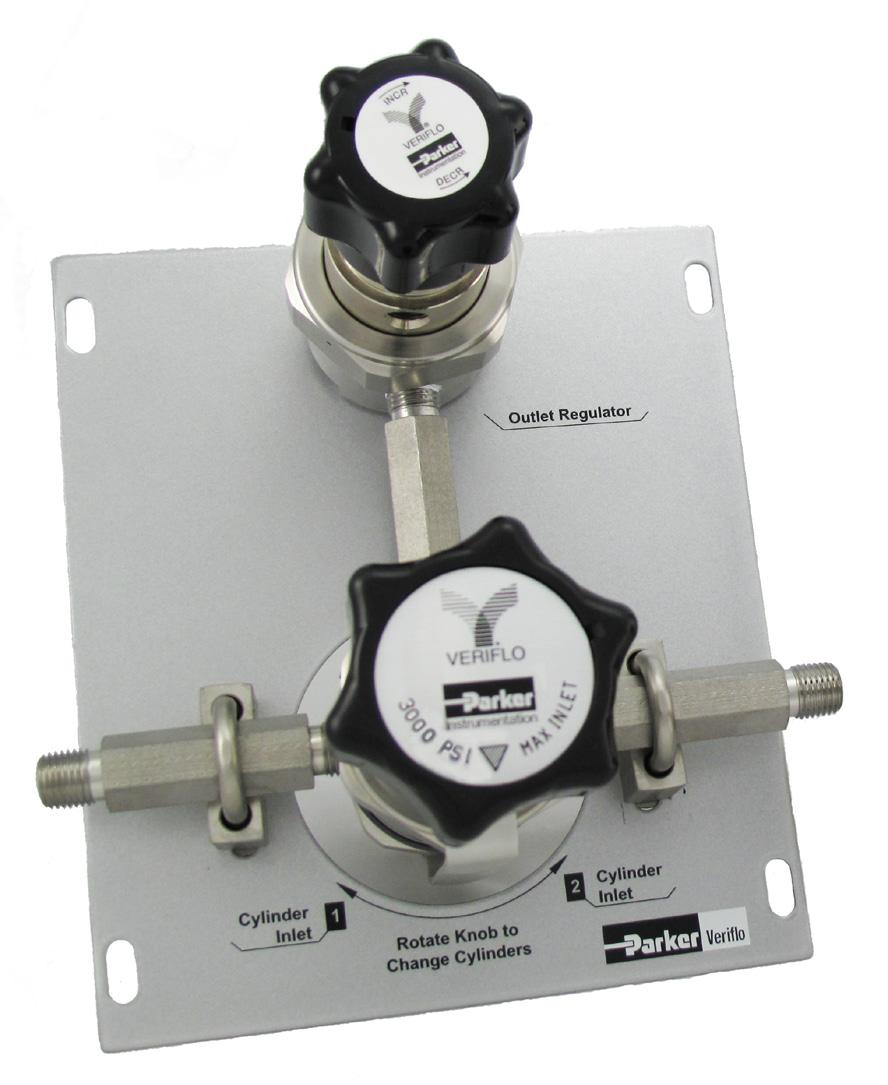
41 COSE Series Fully enclosed to protect internal components. Removable side panels for field maintenance. Allows change out of depleted cylinder(s) while maintaining gas flow. Especially suited for continuous on-stream analyzers. Changeover System Alarm sensor port for systems integration allowing user to monitor gas consumption. Cleaned for Oxygen service. Regulator design integrates positive upward and downward stops which increases cycle life by preventing over stroking of the diaphragm. Maximum Inlet Pressure Temperature 3,000 psig (207 barg) -40 F to 150 F (-40 C to 66 C) Flow Capacity Supply Pressure Effect Seal Internal Seal C v = 0.06 SEMI Flow Coefficient Test #F psig/100psig (.03/7 barg) without Outlet Regulator option Note: Options in blue/italic type are available for the Express Service Program. Changeover System Flow Rates (Based on 400 psig Cylinder Change) COS Model Maximum Recommended Flow COSE 100 S OR COS slpm N 2 COS slpm N 2 COS slpm N 2 COS slpm N 2 Basic Series COSE Pressure Setting COS XXX OR* 70 slpm N = 100 psig * ChangeOver System with optional outlet regulators 150 = 150 psig Notes: 200 = 200 psig ESP COSE s include outlet regulator as standard 250 = 250 psig Configurations without outlet regulator are available at standard lead times. Inlet valves and gauges are standard on all units. For audio/visual annunciator details, see COS Annunciator literature sheet. Annunciator ordering part number: Options A1 = Pressure Switches Includes 2 pressure switches OR = Outlet Regulator Omit = No Outlet Regulator Materials S = 316L Stainless Steel B = Brass 41


42 COSM Series Mini Changeover System, Compact Size Allows change out of depleted cylinder(s) while maintaining gas flow. Especially suited for continuous on-stream analyzers. Compact design reduces footprint. Flow Capacity C v 0.06 Internal Supply Pressure Effect Maximum Inlet Changeover System Flow Rates (Based on 400 psig Cylinder Change) COSM Model COSM slpm N 2 COSM slpm N 2 COSM slpm N 2 COSM slpm N psig/100 psig ( barg/7 barg) 3000 psig (207 barg) Temperature -40 F to 150 F (-40 C to 66 C) Maximum Recommended Flow Max Inlet Pressure of 3,000 psig with 4 delivery options (100, 150, 200 or 250 psig). Outlet Regulator for constant or steady line pressure during change over. Regulator design integrates positive upward and downward stops which increases cycle life by preventing over stroking of the diaphragm. Available in Stainless Steel or Brass Sample: COSM 100 S OR G Finished Order: COSM100SORG 42 1 Pressure Setting 2 Body Material 100 = 100 psig S = 316L Stainless Steel 150 = 150 psig 200 = 200 psig B = Nickel Plated Brass 250 = 250 psig 3 Outlet Regulator OR = Outlet Regulator Std - no other options 4 G Optional Features = Gauges Includes 2 inlet gauges and one outlet gauge
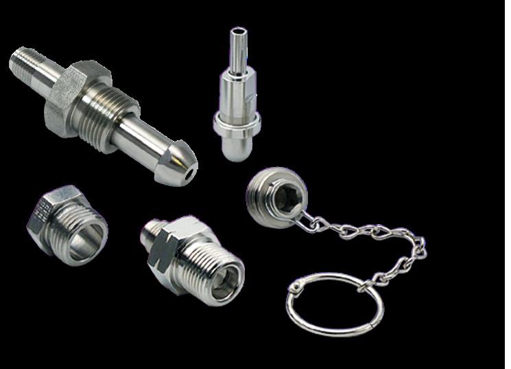
43 CGA Valve Outlet Plugs & Caps (Includes Ring and Chain) 53 Series High Integrity for high purity-specialty gases in Instrument/Analyzer and Process Applications CGA 320, 326, Model 53-30C-3PR 53-33C-3PR Part Material Stainless Steel with Polyethylene disc Stainless Steel with Polyethylene disc F Hex Flat S Hex Flat H Length Gas- Tight* " No 1" 0.54" No GTC-3R Stainless Steel 1-1/8" 0.82" Yes , 677, 678 or P-3TR P-3TR P-3TR C-3PR 53-67C-3PR C-3PR Stainless Steel with PTFE O-Ring Stainless Steel with PTFE O-Ring Stainless Steel with PTFE O-Ring Stainless Steel with Polyethylene disc Stainless Steel with Polyethylene disc Stainless Steel with Polyethylene disc 3/8" 1" Yes 3/8" 1" Yes 3/8" 1" Yes 1-1/4" 0.54" No 1-1/4" 0.54" No 1-3/8" 0.54" No * Components not rated Gas-Tight are intended only to keep valve outlets clean and provide protection to threads. They must not be relied on to contain pressure if the valve leaks or is inadvertently opened. CGA Inlet Connection Components Nipples, Nuts, and Washers 56 Series High Integrity for high purity-specialty gases in Instrument/Analyzer and Process Applications CGA End Connection 1/4" Auto Tube Weld H Overall Length Nipple Model 1-1/4" TW2-P Nipple Part /8" NPT Male 1-1/4" M /4" Auto Tube Weld 1-1/4" TW2-P /8" NPT Male 1-3/4" M /4" Auto Tube Weld 2-5/8" TW2-P /4" NPT Male 2-1/4" M /4" Auto Tube Weld 2-5/8" TW2-P /4" Vac Male 2-3/4" VM2-P /4" NPT Male 3-1/2" M Nut Model Nut Part F1 Flat Hex /16" /4" Washer Model ** Washer Part * T K T K " N/A N/A /8" N/A N/A -P indicates internal surface finish of 9 Ra Electropolish Electropolished I.D. components designated by the -P suffix are cleaned and packaged in a clean room. * All gaskets sold in 25 pack. ** Washer numbers ending in T are PTFE and those ending in K are PCTFE. 43
44 CGA Inlet Connection Components Nipples, Nuts, and Washers 56 Series High Integrity for high purity-specialty gases in Instrument/Analyzer and Process Applications CGA End Connection 1/4" Auto Tube Weld H Overall Length Nipple Model 1-3/4" TW2-P Nipple Part /4" Vac Male 1-3/4" VM2-P Nut Model Nut Part F1 Flat Hex Washer Model ** Washer Part * T /4" Auto Tube Weld 2-1/2" TW2-40-P /8" 1/4" NPT Male 2-1/2" M K /4" NPT Male 4" M /4" Auto Tube Weld 2-1/4' TW2-P /4" Vac Male 2-1/4" VM2-P /8" N/A See Seal Enhancers 1/4" NPT Male 3" M /4" Auto Tube Weld 1-3/4" TW2-P /4" Vac Male 1-3/4" VM2-P T /4" Auto Tube Weld 2-1/2" TW2-40-P /8" 1/4" NPT Male 2-1/2" M K /4" NPT Male 4" M /4" Auto Tube Weld 2-5/16" TW2-P /4" Vac Male 2-1/4" VM2-P /8" N/A See Seal Enhancers 1/4" NPT Male 3" M /4" Auto Tube Weld 2-5/16" TW2-P /4" Vac Male 2-1/4" VM2-P /4" Auto Tube Weld 2-1/2" TW2-40-P /8" N/A See Seal Enhancers 1/4" NPT Male 3" M /4" NPT Male 4" M /4" Auto Tube Weld 2-5/8" TW2-P /4" Vac Male 2-3/4" VM2-P /4" Auto Tube Weld 2-1/2" TW2-40-P /4" NPT Male 3-1/2" M /4" NPT Male 4" M /4" NPT Male 4-1/2" M /4" Auto Tube Weld 2-1/4" TW2-P /4" Vac Male 2-1/4" VM2-P /4" NPT Male 3" M /8" N/A N/A /8" N/A N/A -P indicates internal surface finish of 9 Ra Electropolish Electropolished I.D. components designated by the -P suffix are cleaned and packaged in a clean room. * All gaskets sold in 25 pack. ** Washer numbers ending in T are PTFE and those ending in K are PCTFE. 44
45 CGA Inlet Connection Components Nipples, Nuts, and Washers 56 Series High Integrity for high purity-specialty gases in Instrument/Analyzer and Process Applications CGA End Connection 1/4" Auto Tube Weld H Overall Length Nipple Model 2-1/4" TW2-P Nipple Part /4" Vac Male 2-1/4" VM2-P /4" NPT Male 3" M /4" Auto Tube Weld 2-5/8" TW2-P /4" Vac Male 2-3/4" VM2-P /4" Auto Tube Weld 2-1/2" TW2-40-P /4" NPT Male 3-1/2" M /4" NPT Male 4" M /4" NPT Male 4-1/2" M /4" Auto Tube Weld 2-5/8" TW2-P /4" Vac Male 2-3/4" VM2-P /4" Auto Tube Weld 2-1/2" TW2-40-P /4" NPT Male 3-1/2" M /4" NPT Male 4" M /4" NPT Male 4-1/2" M /4" Auto Tube Weld 2-3/16" TW2-P /4" Vac Male 1-7/8" VM2-P /4" Auto Tube Weld 2-1/2" TW2-40-P /4" NPT Male 2-5/8" M /4" NPT Male 4" M /4" Auto Tube Weld 2-3/16" TW2-P /4" Vac Male 1-7/8" VM2-P /4" Auto Tube Weld 2-1/2" TW2-40-P /4" NPT Male 2-5/8" M /4" NPT Male 4" M /4" Auto Tube Weld 2-1/2" TW2-P /4" Vac Male 2" VM2-P /4" NPT Male 2-3/8" M /4" Auto Tube Weld 2-1/2" TW2-P /4" Vac Male 2" VM2-P /4" NPT Male 2-1/2" M Nut Model Nut Part F1 Flat Hex Washer Model ** Washer Part * /8 N/A N/A /8" N/A N/A /8" N/A N/A /4" /4" /4" T K T K T K /4" T P indicates internal surface finish of 9 Ra Electropolish Electropolished I.D. components designated by the -P suffix are cleaned and packaged in a clean room. * All gaskets sold in 25 pack. ** Washer numbers ending in T are PTFE and those ending in K are PCTFE. 45
46 CGA Outlet Adapters, Blank Caps & Plugs 57 Series High Integrity for high purity-specialty gases in Instrument/Analyzer and Process Applications CGA End Connection Model Part H Overall Length F2 Flat Hex 180 1/4" NPT Female M4F /4 Blank Cap FXX " 296 1/4" VacuSeal Male F4VM " 1-1/8" 1/4" NPT Female F4F " Blank Plug MXX " 320 1/4" VacuSeal Male M4VM " 1" 1/4" NPT Female M4F " Blank Plug MXX " 326 1/4" VacuSeal Male M4VM " 1" 1/4" NPT Female M4F " Blank Plug MXX " 330 1/4" VacuSeal Male M4VM " 1" 1/4" NPT Female M4F " Blank Plug MXX " 346 1/4" VacuSeal Male M4VM " 1" 1/4" NPT Female M4F " Blank Plug MXX " 350 1/4" VacuSeal Male M4VM " 1" 1/4" NPT Female M4F " Blank Cap FXX " 510 1/4" VacuSeal Male F4VM " 1-1/4" 1/4" NPT Female F4F " Blank Plug MXX " 540 1/4" VacuSeal Male M4VM " 1" 1/4" NPT Female M4F " Blank Cap FXX " 580 1/4" VacuSeal Male F4VM " 1-1/4" 1/4" NPT Female F4F " Blank Cap FXX ' 590 1/4" VacuSeal Male F4VM " 1-1/4" 1/4" NPT Female F4F " Blank Plug MXX " 660 1/4" VacuSeal Male M4VM " 1-1/8" 1/4" NPT Female M4F " Blank Plug MXX " 670 1/4" VacuSeal Male M4VM " 1-1/8" 1/4" NPT Female M4F " 678 Blank Plug MXX " 1/4" VacuSeal Male M4VM " 1-1/8" Blank Plug MXX " 679 1/4" VacuSeal Male M4VM " 1-1/8" 1/4" NPT Female M4F " Blank Cap CGA 580 Blank Plug CGA 350 Vac Male CGA 350 NPT Female CGA
47 CGA Pigtail Connections 58 Series High Integrity for high purity-specialty gases in Instrument/Analyzer and Process Applications CGA Drawing Model Part H Overall Length F1 Hex Flat F2 Hex Flat Washer Material 296 B TW2-P /8" 1-1/8" 320 A TW2-P /8" 1" PCTFE 326 A TW2-P /8" 1" 330 A TW2-P /8" 1" PCTFE 346 A TW2-P /8" 1" 350 A TW2-P /8" 1" 510 B TW2-P /8" 1-1/4" 540 A TW2-P /8" 1" 555 A TW2-P /8" 1" 580 B TW2-P /8" 1-1/4" 590 B TW2-P /8" 1-1/4" 660 A TW2-P /4" 1-1/8" PCTFE 670 A TW2-P /4" 1-1/8" PCTFE 678 A TW2-P /4" 1-1/8" PCTFE 679 A TW2-P /4" 1-1/8" PTFE Electropolished I.D. components designated by the -P suffix are cleaned and packaged in a clean room. -P indicates internal surface finish of 9 Ra Electropolish Seal Enhancers (10 Per Package) Material Model Part A Overall Length B Overall Length C Overall Length D Overall Length Nickel NI Nickel NI Nickel NI A B 47
48 Washers (25 Per Package) High Integrity for high purity-specialty gases in Instrument/Analyzer and Process Applications CGA Material Model Part A Overall Length H Overall Width E Overall Bore 170 PTFE T PCTFE K PTFE T PCTFE K , 330 PTFE T , 330 PCTFE K , 670 PTFE T , 670 PCTFE K PTFE T PCTFE K PTFE T H A E Flexible Pigtails Part Material 316 Double Braided Stainless Steel Hose 316 Double Braided Stainless Steel Hose 316 Double Braided Stainless Steel Hose 316 Double Braided Stainless Steel Hose 316 Double Braided Stainless Steel Hose 316 Double Braided Stainless Steel Hose End Connections 1/4 MNPT x 1/4 FNPT 1/4 MNPT x 1/4 FNPT 1/4 MNPT x 1/4 FNPT 1/4 MNPT x 1/4 FNPT 1/4 MNPT x 1/4 FNPT 1/4 MNPT x 1/4 FNPT H Overall Length Maximum Working Pressure 12" 3625 PSI 24" 3625 PSI 36" 3625 PSI 48" 3625 PSI 60" 3625 PSI 72" 3625 PSI 48 Torque Wrenches 77 Series Model Part Factory Set Torque For Use With CGA 326, 346, 350 Hex Flat TW ft-lbs Nickel Seal Enhancers 1-1/8 Torque wrenches are specifically designed for use with the Compressed Gas Association s CGA 326, 346 and 350 series of connections. Torque is factory set to the CGA recommendations. Calibration service is also available and is recommended every six months or 4,000 cycles, whichever comes first.
49 Notes 49
50 Express Service Program Available on Select Products Only The Express Service Program is the next generation of customer service designed to provide customers with an array of standard products in a 5 day delivery window. The ESP program offers a standard lead time of 5 working days from receipt of order to the ship date. Using the shown, you can identify the product configurations offered in the program by the Blue Italic Print. If the configuration you select is in black print, the product will be ready to ship in the standard lead time. Please contact your local Parker Hannifin Distributor or the factory for any questions regarding the scope of the Express Service Program. Fairprene is a registered trademark of DuPont Performance Elastomers L.L.C. Vespel is a registered trademark of DuPont Performance Elastomers L.L.C. Hastelloy C-22 is a registered trademark of Haynes International, Inc. NACE is a trademark of NACE International Foundation A-LOK is a registered trademark of Parker Hannifin Corporation VeriClean is a trademark of Parker Hannifin Corporation VacuSeal is a trademark of Parker Hannifin Corporation SilcoNert 1000 is a trademark of SilcoTek Corporation Inconel is a registered trademark of Special Metals Corporation Inconel X750 is a registered trademark of Special Metals Corporation Monel is a registered trademark of Special Metals Corporation PEEK is a trademark of Victrex plc. Safety Guide and Installation and Operating Instructions available at OFFER OF SALE: The items described in this document are hereby offered for sale by Parker-Hannifin Corporation, its subsidiaries or its authorized distributors. This offer and its acceptance are governed by the provisions stated in the detailed Offer of Sale elsewhere in this document or available at WARNING USER RESPONSIBILITY FAILURE OR IMPROPER SELECTION OR IMPROPER USE OF THE PRODUCTS DESCRIBED HEREIN OR RELATED ITEMS CAN CAUSE DEATH, PERSONAL INJURY AND PROPERTY DAMAGE. THIS DOCUMENT IS FOR REFERENCE ONLY. PLEASE CONSULT FACTORY FOR LATEST PRODUCT DRAWINGS AND SPECIFICATIONS This document and other information from Parker-Hannifin Corporation, its subsidiaries and authorized distributors provide product or system options for further investigation by users having technical expertise. The user, through its own analysis and testing, is solely responsible for making the final selection of the system and components and assuring that all performance, endurance, maintenance, safety and warning requirements of the application are met. The user must analyze all aspects of the application, follow applicable industry standards, and follow the information concerning the product in the current product catalog and in any other materials provided from Parker or its subsidiaries or authorized distributors. To the extent that Parker or its subsidiaries or authorized distributors provide component or system options based upon data or specifications provided by the user, the user is responsible for determining that such data and specifications are suitable and sufficient for all applications and reasonably foreseeable uses of the components or systems. Proposition 65 Warning: This product contains chemicals known to the state of California to cause cancer or birth defects or other reproductive harm. 50


51 Parker s Motion & Control Technologies At Parker, we re guided by a relentless drive to help our customers become more productive and achieve higher levels of profitability by engineering the best systems for their requirements. It means looking at customer applications from many angles to find new ways to create value. Whatever the motion and control technology need, Parker has the experience, breadth of product and global reach to consistently deliver. No company knows more about motion and control technology than Parker. For further info call C-Parker. AEROSPACE Key Markets Aircraft engines Business & general aviation Commercial transports Land-based weapons systems Military aircraft Missiles & launch vehicles Regional transports Unmanned aerial vehicles Key Products Flight control systems & components Fluid conveyance systems Fluid metering delivery & atomization devices Fuel systems & components Hydraulic systems & components Inert nitrogen generating systems Pneumatic systems & components Wheels & brakes FLUID & GAS HANDLING Key Markets Aerospace Agriculture Bulk chemical handling Construction machinery Food & beverage Fuel & gas delivery Industrial machinery Mobile Oil & gas Transportation Welding HYDRAULICS Key Markets Aerospace Aerial lift Agriculture Construction machinery Forestry Industrial machinery Mining Oil & gas Power generation & energy Truck hydraulics Key Products Brass fittings & valves Diagnostic equipment Fluid conveyance systems Industrial hose PTFE & PFA hose, tubing & plastic fittings Rubber & thermoplastic hose & couplings Tube fittings & adapters Quick disconnects Key Products Diagnostic equipment Hydraulic cylinders & accumulators Hydraulic motors & pumps Hydraulic systems Hydraulic valves & controls Power take-offs Rubber & thermoplastic hose & couplings Tube fittings & adapters Quick disconnects Veriflo CLIMATE CONTROL Key Markets Agriculture Air conditioning Food, beverage & dairy Life sciences & medical Precision cooling Processing Transportation Key Products CO2 controls Electronic controllers Filter driers Hand shut-off valves Hose & fittings Pressure regulating valves Refrigerant distributors Safety relief valves Solenoid valves Thermostatic expansion valves PNEUMATICS Key Markets Aerospace Conveyor & material handling Factory automation Life science & medical Machine tools Packaging machinery Transportation & automotive Key Products Air preparation Brass fittings & valves Manifolds Pneumatic accessories Pneumatic actuators & grippers Pneumatic valves & controls Quick disconnects Rotary actuators Rubber & thermoplastic hose & couplings Structural extrusions Thermoplastic tubing & fittings Vacuum generators, cups & sensors ELECTROMECHANICAL Key Markets Aerospace Factory automation Life science & medical Machine tools Packaging machinery Paper machinery Plastics machinery & converting Primary metals Semiconductor & electronics Textile Wire & cable Key Products AC/DC drives & systems Electric actuators, gantry robots & slides Electrohydrostatic actuation systems Electromechanical actuation systems Human machine interface Linear motors Stepper motors, servo motors, drives & controls Structural extrusions PROCESS CONTROL Key Markets Chemical & refining Food, beverage & dairy Medical & dental Microelectronics Oil & gas Power generation Key Products Analytical sample conditioning products & systems Fluoropolymer chemical delivery fittings, valves & pumps High purity gas delivery fittings, valves & regulators Instrumentation fittings, valves & regulators Medium pressure fittings & valves Process control manifolds FILTRATION Key Markets Food & beverage Industrial machinery Life sciences Marine Mobile equipment Oil & gas Power generation Process Transportation Key Products Analytical gas generators Compressed air & gas filters Condition monitoring Engine air, fuel & oil filtration & systems Hydraulic, lubrication & coolant filters Process, chemical, water & microfiltration filters Nitrogen, hydrogen & zero air generators SEALING & SHIELDING Key Markets Aerospace Chemical processing Consumer Energy, oil & gas Fluid power General industrial Information technology Life sciences Military Semiconductor Telecommunications Transportation Key Products Dynamic seals Elastomeric o-rings EMI shielding Extruded & precision-cut, fabricated elastomeric seals Homogeneous & inserted elastomeric shapes High temperature metal seals Metal & plastic retained composite seals Thermal management 51