Saluda Hydro Operations. William R. Argentieri, P.E. Fossil & Hydro Technical Services
|
|
|
- Malcolm Bailey
- 5 years ago
- Views:
Transcription


1 Saluda Hydro Operations William R. Argentieri, P.E. Fossil & Hydro Technical Services
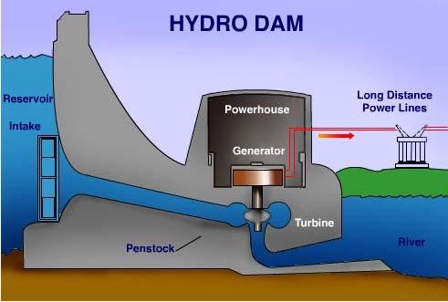
2 Hydropower Basics Hydroelectric plants convert potential energy of water into kinetic energy to drive a generator. Water flows from headwater elevation to tailwater elevation through a hydraulic turbine, which is connected to a generator.
3
4 Saluda Hydro Basic Facts Saluda Hydroelectric Project was built between 1927 and Saluda Hydro originally had four turbinegenerator units installed. A fifth unit was added in Generation capacity is 206 MW Hydraulic capacity is 18,000 CFS (8 million GPM!)
5 Drainage Basin Area 2,420 sq. mi. Reservoir surface area 50,000 acres at elev SPD. Reservoir capacity 1,600,000 ac-ft at elev SPD.
6 Units 1-4 Units 1 4 turbines are Francis reaction type, built by S. Morgan Smith Co., and develop over 55,000 HP each at RPM. Design head is 180 feet. Units 1-4 generators are Westinghouse machines operating at 13,800 VAC. Units 1, 2 & 4 generators are rated at 32.5 MW. Unit 3 was rewound in 1966 and is now rated at 42.3 MW.

7 Rotation Unit 1 4 Turbine Runner (Bottom View)

8 Francis Turbine Runner Similar to Saluda 1-4

9
10 Unit 5 Unit 5 turbine is also a Francis reaction type, built by Baldwin-Lima-Hamilton and developing 98,300 HP at RPM. Design head is 156 feet. Unit 5 generator is a General Electric machine rated at 75 MW at 13,800 VAC.
11 Intake Towers Towers 1 4 are 30 feet in diameter and 223 feet tall. Each tower has two 9 ft. by 14 ft. Broome roller gates with sills at bottom of reservoir - elevation 160 ft. Saluda Plant Datum (SPD). Gates are operated by electric hoists in brick machine houses atop each tower.
12 Intake Towers Tower 5 is 60 feet in diameter and 223 feet tall. It was designed to supply two future units similar to the original four. It now supplies Unit 5, which is about twice as large as the original units. Tower 5 has six 10 ft. by 10 ft. Broome roller gates with sills at elevation ft. SPD.
13 Emergency Spillway Emergency spillway is used to release water from reservoir in excess of what can be passed through the plant and stored in reservoir. Only used to prevent uncontrolled reservoir rise which threatens to overtop the dam. Spillway is tested each year by opening one gate fully, and raising others one foot each. Spillway is NOT the original Saluda River channel. It is a man-made channel.
14 Emergency Spillway Four gates 37.5 ft W x 25 ft H original Two gates 46.5 ft W x 32 ft H added 1946 Each of the six spillway gates has its own hoist. Primary power for gate hoists is overhead electric. Backup generator is located near spillway. Gates can be operated using compressed air if electric hoist motors fail.
15 Spillway Hydraulic Capacity Flow through the spillway depends on number of gates opened, how far the gates are raised, and the reservoir elevation. Spillway hydraulic capacity with all gates fully open and reservoir at el. 360 SPD is about 90,000 CFS (five times powerhouse hydraulic capacity). Maximum spillway hydraulic capacity with all gates fully open and reservoir at el. 377 SPD is about 197,000 CFS.
16 Spillway Rating Curve - All Gates Fully Open 380 Res. Elev. (Ft. MSL) , , , ,000 Flow (CFS)
17 Emergency Spillway Spillway has been operated four times during floods in 1936, 1964, 1965, and Installation of Unit 5 increased ability to pass flood flows through powerhouse, reducing frequency of spillway operation. Spillway operation to pass floods has not been required since 1969.
18 Project Operation Saluda Hydro is normally operated as a reserve plant, to quickly replace other system generation which is offline for some reason. Saluda Hydro can respond quickly to provide generation and keep the system stable. Occasionally Saluda Hydro is used to augment other system generation at times of extremely high demand. Saluda also has black start capability to get system back up after catastrophic outage.
19 Project Operations Reservoir Level Project License sets a minimum reservoir elevation of 345 ft. SPD, and a maximum reservoir elevation of 360 ft. SPD. SCE&G normally operates the reservoir in the range of 350 to 358 ft. SPD. Reservoir is occasionally drawn down to near el. 345 ft. SPD for vegetation control or other maintenance work.
20 Project Operations Reservoir Level SCE&G sets target reservoir elevations for each month of the year, to allow for seasonal inflow variations. These target elevations may vary from year to year, depending on inflow available, maintenance activities, unit availability, etc. It is important to remember that each year is different there is no normal year. There is no one Rule Curve for reservoir operation.
21 December Example Target Elevation & Month End Elevation January February March April May June July August September October November Elev. (ft SPD)
22 Historical Floods August 1928: 58,200 CFS (During project construction) March 1929: 53,600 CFS (During project construction) October 1929: 67,000 CFS (During project construction, flood of record for basin) April 1936: 61,600 CFS (Highest recorded lake level SPD resulted) 4 Gates Opened April 1964: 38,800 CFS 2 Gates Opened June 1965: 53,200 CFS 4 Gates Opened April 1969: 35,700 CFS 2 Gates Opened

23 Powerhouse Foundation During Flood, October 1929

24 Powerhouse Foundation After Flood, October 1929
25 Inflow Design Flood (IDF) The IDF is the largest hypothetical flood which can be safely accommodated by the project. The IDF for Saluda is the Probable Maximum Flood (PMF) - the largest flood determined to be probable in the basin. The PMF results from a hypothetical storm of optimum size, shape, and orientation to produce maximum runoff in the drainage basin. The PMF inflow for Saluda Hydro is 572,300 CFS almost 10 times the flood of record.
26 Inflow Design Flood (IDF) Dam has been modified twice to accommodate updated estimates of the PMF. 1940s Dam crest raised 3 feet to el SPD, two spillway gates added Latest PFM lake level would be SPD. Sheet pile freeboard wall added to dam crest top of wall el SPD. Flow Forecast Model was developed to predict reservoir level during floods.

27 Sheet Pile Freeboard Wall Construction
28 Project Operation Flow Forecast Model Flow Forecasting Model (FFM) is a computer based model used to predict inflow and reservoir rise from storm events in the basin. The FFM uses NWS forecasts and USGS rain and flow gage data as input to a hydrologic/hydraulic model which predicts runoff and stream flow. SCE&G uses the FFM to decide how much to lower the reservoir in advance of a large storm system, how much to generate to maintain the lake level, and whether spillway operation is required.

29 FFM Screen Current Conditions

30 FFM Screen NWS Precipitation Forecast

31 FFM Screen Model Input Screen - General

32 FFM Screen Model Input Screen - Turbines

33 FFM Screen Model Input Screen - Gates
34 Project Operation Flow Forecast Model The FFM can model different what if scenarios various combinations of powerhouse and spillway operations can be input to determine effect on reservoir level. The FFM models conditions at Buzzards Roost (Lake Greenwood), as well as Saluda Hydro. FFM database is updated daily from USGS and NWS servers.
35 Project Operation - Storms Floods cause high tailwater conditions at the Saluda powerhouse, reducing generating capability due to lower effective head. High tailwater can also flood portions of the powerhouse if precautions are not taken stop logs at work bay door, seals at ventilation louvers. Powerhouse had to be sealed during the 1965 flood tailwater rose to almost 199 ft. SPD.
36 Project Operation - Restrictions Informal agreement in place with SCDHEC to maintain 180 CFS minimum flow in lower Saluda River. McMeekin Station discharges cooling water to Unit 2. McMeekin NPDES Permit requires that Saluda Hydro discharge 2,500 CFS when Unit 2 is operated, or when cooling water is bypassed to tailrace.
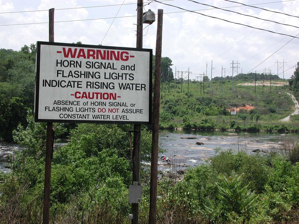
37 Project Operation Restrictions Unit 5 operations are often restricted during summer due to fish schooling around intake tower hydroacoustic system detects presence of fish and displays in System Control Room.

38 McMeekin Cooling Water Bypass June 2005
39 Project Operation DO Issues During late summer and fall, dissolved oxygen in reservoir becomes depleted below about 75 feet depth. SCE&G has installed turbine vents and hub baffles to enhance air entrainment into turbine discharges. Venting efficiency varies with load on unit generally better venting occurs in middle third of load range.
40 Project Operation DO Issues SCE&G uses Look Up Tables (LUTs) to dispatch units according to reservoir DO levels and venting capability of each unit. Attempt to optimize operations to mitigate DO impact to lower Saluda River. This usually results in having to spread load over several units during low DO season.
41 Project Maintenance - Powerhouse Normal preventive maintenance work is performed constantly. Periodic maintenance requiring brief unit outage is performed as required during the year. Major maintenance requiring prolonged unit outage or dewatering of a unit is scheduled for low demand time of year, if possible.
42 Project Maintenance - Powerhouse Dewatering of a unit requires closing butterfly valve for Units 1 4, or closing head gate at tower for Unit 5. Dewatering of a penstock requires closing head gate at tower. Dewatering penstock and scroll case can take as long as a week, depending on how well gates seal.
43 Project Maintenance - Dam Lake is occasionally drawn down to about el. 345 SPD for maintenance of dam and appurtenant structures, or for control of vegetation in reservoir. Repair of the upstream riprap armor planned for winter 2006 will require reservoir draw down to about el. 348 SPD.
44 Public Safety Plan Submitted as part of the license application. Provides locations of operational sirens, warning signs, strobe lights, etc. On the lake we have warning signs only at the public access locations. On the river, we have sirens, warning signs, and strobe lights at two locations, Mill Race Rapids at the Zoo and Hope Ferry Landing/ Saluda Shoals Park.
45
46 Dam Surveillance Program SCE&G performs monthly dam surveillance in accordance with FERC regulations. Both original dam and backup dam are instrumented to monitor water level and pressure, seepage, and deformation. SCE&G technicians collect instrument data and inspect dam at least monthly, more often if unusual conditions present. Dam is surveyed semi-annually. Surveillance Report filed with FERC annually.
47 Emergency Action Plan (EAP) SCE&G maintains an Emergency Action Plan (EAP) detailing response to potential or actual failure of dam. EAP contains procedures used to notify local, state, and federal officials in event of dam related emergency and inundation maps showing the flood area during the Probable Maximum Precipitation and Sunny Day failure.
48 Emergency Action Plan (EAP) During the dam remediation we installed 10 early warning sirens that are still active today. We also published an Emergency Information Brochure to provide guidance to the public should these sirens need to be activated. This brochure is mailed to those in the inundation zone and can be found on the SCE&G website. Purpose is to allow coordination of downstream notification/evacuation if required.
49 Emergency Action Plan (EAP) EAP is updated annually with current contact information for response agencies. EAP tabletop and functional exercises are conducted every 5 years to test communications channels and procedures. Plant personnel attend annual EAP training session on procedures.
50 Questions?