Appendix E. Civil Design and Cost Engineering
|
|
|
- Teresa Hawkins
- 5 years ago
- Views:
Transcription
1 Appendix E Civil Design and Cost Engineering
2 Appendix E1 Civil Design

3 Civil Design Appendix South San Francisco Bay Shoreline Study U.S. Army Corps of Engineers, San Francisco District September 2015 USACE San Francisco District South San Francisco Bay Shoreline Phase I Study September 2015 E1-1
4 . USACE San Francisco District South San Francisco Bay Shoreline Phase I Study September 2015 E1-2
5 Civil and Cost Appendix Contents 1.0 General... E Purpose... E Authority... E Background... E Study Area and Existing Conditions... E Alternative Selection and Project Development... E Flood Risk Management Options... E Levee Design Considerations... E Alignments... E Artesian Slough Closures... E Levels of Protection... E FRM Final Array... E FRM Option 1A Alviso North and WPCP North, 200-year event... E FRM Option 1B Alviso North and WPCP North, 100-year event... E FRM Option 1C Alviso North and WPCP North with no Tide Gate, 50-year event... E FRM Option 1D Alviso North and WPCP North, 25-year event... E FRM Option 2 Alviso North and WPCP South, 100 year event... E FRM Option 3 Alviso RR and WPCP North, 200-year event... E FRM Option 4 Alviso South and WPCP South, 50-year event... E FRM Option 5 Alviso RR and WPCP South, 100-year event... E FRM Option 6 Alviso South and WPCP South, 100-year event... E FRM Option 7 Alviso North and WPCP South, 25-year event... E FRM Option 8 Alviso North and WPCP South, 200-year event... E Ecosystem Restoration Measures... E Transitional Habitat... E Tidal Marsh Restoration... E Locally Preferred Plan... E Flood Risk Management Levees... E Alignment... E Design, Considerations, and Construction... E Closure Structures... E Railroad Closure Flood Gate... E Artesian Slough Closure Tide Gate... E Ecosystem Restoration... E Transitional Habitat Alignment... E Design, Consideration, and Construction... E Pond/Tidal Marsh Restoration... E National Economic Development Plan... E Flood Risk Management Levees... E Alignment... E Design, Considerations, and Construction... E Closure Structures... E Railroad Closure Flood Gate... E Artesian Slough Closure Tide Gate... E Ecosystem Restoration... E Transitional Habitat Alignment... E Design, Consideration, and Construction... E Pond/Tidal Marsh Restoration... E1-25 USACE San Francisco District South San Francisco Bay Shoreline Phase I Study September 2015 E1-3
6 Civil and Cost Appendix 5.0 Recreation Mitigation... E Bridges... E Bay Trails... E Real Estate... E Easements and R/W Requirements... E Borrow Locations... E Disposal and Storage Area... E Staging Area... E Relocations and Modifications... E Overview... E LPP and NED... E Development of Construction Quantities... E Levee and Transitional Habitat Quantities... E Pond Restoration Quantities... E Recreation Mitigation Quantities... E Bay Trail Quantities... E Bridge Quantities... E Cost Estimates... E Value Engineering... E1-30 Figures Figure 1 Shoreline Study Area Figure 2 Option 1A Plan View Figure 3 Option 1B Plan View Figure 4 Option 1C Plan View Figure 5 Option 1D Plan View Figure 6 Option 2 Plan View Figure 7 Option 3 Plan View Figure 8 Option 4 Plan view Figure 9 Option 5 Plan View Figure 10 Option 6 Plan View Figure 11 Option 7 Plan View Figure 12 Option 8 Plan View Figure 13A Pond Restoration 2020 Figure 13B Pond Restoration 2025 Figure 13C Pond Restoration 2030 Figure 14 Levee Volume Sample Calculations Figure 15 Transitional Habitat Fill Sample Calculations Figure 16 Existing Levee and Foundation Excavation Sample Calculations Figure 17 Hydroseeding Sample Calculations Figure 18 Aggregate Base / Asphalt Concrete Sample Calculations Figure 19 Gravel Sample Calculations Figure 20 Clearing and Grubbing Sample Calculations Figure 21 Stripping Sample Calculations Figure 22 Wick Drains Sample Calculations Figure 23 Utilities Relocation Sample Calculations Figure 24 Utilities Relocation Sample Calculations Figure 25 Ecotone Hydroseeding Sample Calculations Figure 26 Levee Breaches Sample Calculations USACE San Francisco District South San Francisco Bay Shoreline Phase I Study September 2015 E1-4
7 Civil and Cost Appendix Figure 27 Pilot Channels Sample Calculations Figure 28 Ditch Blocks Sample Calculations Figure 29 Internal Berm Interim Raising Sample Calculations Figure 30 Bay Trails Recreation Mitigation Sample Calculations Quantities Quantities 1 Quantities for NED Levees and Transitional Habitat Bench Quantities 2 Quantities for LPP Levees and Transitional Habitat 30:1 Ecotone Quantities 3 Quantities for Pond Restoration Outboard Levee Breaches Quantities 4 Quantities for Pond Restoration Internal Berm Breaches Quantities 5 Quantities for Pond Restoration Pilot Channels Quantities 6 Quantities for Pond Restoration Ditch Blocks Quantities 7 Quantities for Pond Restoration Internal Berm Interim Raising Quantities 8 Quantities for Bay Trail Recreation Mitigation Quantities 9 Quantities for Pedestrian Bridges Mitigation Tables Table 1. Summary of Final Array of FRM Options... E1-10 Table 2. Transitional-Upland Slope Design... E1-16 Table 3. Outboard Levee Breach Cross-Sections... E1-18 Table 4. Internal Berm Breach Cross-Sections... E1-18 Table 5. Internal Berm Interim Raising... E1-19 Table 6. Pilot Channel Cross-Section Dimensions and Lengths... E1-19 Table 7. Locally Preferred Plan Summary... E1-20 Table 8. National Economic Development Plan Summary... E1-23 Table 9. Cost Summary... E1-29 Attachments 1 Attachment I NED Plans, Profiles and Sections Attachment II LPP Plans, Profiles and Sections Appendices 1 Existing Utilities Information Technical Memorandum USACE San Francisco District South San Francisco Bay Shoreline Phase I Study September 2015 E1-5
8 Civil and Cost Appendix 1.0 General 1.1 Purpose This civil design report is a technical appendix to the South San Francisco Bay Shoreline Study (Shoreline Study) and was developed by HDR and the USACE San Francisco District. The purpose of this Civil Design Appendix is to provide additional information regarding the technical aspects of engineering elements. These technical details presented pertain to the construction of the new or improved levees that protect the community of Alviso, CA as authorized by the Committee on Transportation and Infrastructure of the U.S. House of Representatives on July 24, 2002 (Docket 2697). The purpose of this study is to determine the feasibility and the Federal interest of a combined tidal Flood Risk Management (FRM) and Ecosystem Restoration (ER) project. 1.2 Authority The Shoreline Study is being prepared in response to the resolution adopted by the Committee on Transportation and Infrastructure of the U.S. House of Representatives on July 24, 2002, for the South San Francisco Bay Shoreline Study (Shoreline Study), California (Docket 2697), which reads as follows: Resolved by the Committee on Transportation and Infrastructure of the United States House of Representatives, That the Secretary of the Army is requested to review the Final Letter Report for the San Francisco Bay Shoreline Study, California, dated July 1992, and all related interims and other pertinent reports to determine whether modifications to the recommendations contained therein are advisable at the present time in the interest of tidal and fluvial flood damage reduction, environmental restoration and protection and related purposes along the South San Francisco Bay shoreline for the counties of San Mateo, Santa Clara and Alameda, California. 1.3 Background The Shoreline Study was originally authorized by Congress in 1976 to assess the need for flood risk management in the San Francisco South Bay (South Bay). A subsequent flood control study, issued in 1992 by the U.S Army Corps of Engineers (Corps), found that a Federal flood management project along the South Bay shoreline was not economically justifiable mainly because it was determined that Cargill Salt would continue to maintain their existing salt pond levees due to their economic interest in keeping ocean and river water from diluting the brines of its salt-making operations. These salt pond levees were not engineering levees; however, they provided incidental flood risk management for the surrounding communities. In 2003, the Federal and state governments began planning a restoration project when they acquired 15,100 acres of salt ponds from Cargill Salt in the South Bay. The planned restoration project would affect the utility of the salt pond levees as flood protection structures. As a result, the U.S. House of Representatives requested that the Corps review its previous study on USACE San Francisco District South San Francisco Bay Shoreline Phase I Study September 2015 E1-6
9 Civil and Cost Appendix flood management along the South Bay shoreline as well as to include environmental restoration and protection, and tidal and fluvial flood risk management. The Corps completed an initial reconnaissance analysis in September 2004, which determined that due to the current and future anticipated conditions in the South Bay, it was likely that a Federal flood risk management and ecosystem restoration project would be justified. On October 24, 2005, the Corps, the U.S. Fish and Wildlife Service (FWS), the Santa Clara Valley Water District (SCVWD) and the California State Coastal Conservancy (Conservancy) kicked off the first study phase of the Shoreline Study. This first phase covers the southern portion of the South Bay, including the Alviso Ponds and other lands and waters stretching from southwest Fremont to Palo Alto. 1.4 Study Area and Existing Conditions The Shoreline Study (Figure 1 - Study Area) encompasses shoreline and floodplain areas, three groups of former salt production ponds, and other parcels that represent additional opportunities for flood risk management and/or ecosystem restoration benefits along the South Bay in Northern California. The Shoreline Study area extends from the Ravenswood Ponds in San Mateo and State Route (SR) 92 in the city of Hayward south along both sides of the bay to its southern end, and includes adjacent areas that may be flooded by the bay and/or that may offer opportunities for restoration of tidal and related habitats. The study area for this phase of the project is located near the town of Alviso in San Jose, CA and adjacent to the San Jose Santa Clara Water Pollution Control Plant (WPCP). There are three significant streams in the area, Alviso Slough, which is to the West of Alviso; Coyote Bypass, which is north of the water treatment plant; and Artesian Slough, which flows out of the water treatment plant. Alviso is surrounded by the New Chicago Marsh, and Ponds A12, A13 and A16. Pond A18 is to the northwest of the water treatment plant. The foundation soils in the study area consist primarily of Bay Mud. Bay Mud is normally consolidated and typically very weak clayey/silty soil. The Bay Mud is approximately 5 to 40 feet thick in the project area and contains occasional inclusions of organics in the upper 10 feet of the soil profile. Near Artesian Slough is the Don Edwards Education Center which must be taken into consideration during the analysis. Also on the project site is the Union Pacific Rail Road running in a North-South direction on the west side of Alviso, and the Zanker Landfill to the southern portion of Artesian Slough. 2.0 Alternative Selection and Project Development 2.1 Flood Risk Management Options Several Flood Risk Management (FRM) options were formulated to provide an array of flood management options at differing levels of protection (LOP) across several potential alignments. USACE San Francisco District South San Francisco Bay Shoreline Phase I Study September 2015 E1-7
10 Civil and Cost Appendix The purpose of this array was to provide a wide range of options that would allow for estimating quantities, costs, and benefits at each alignment at each LOP. This array was used to evaluate and compare options to determine the National Economic Development (NED) Plan and the Locally Preferred Plan (LPP). Each of these FRM options involves the construction of new, engineered levees Levee Design Considerations Where levees will be constructed in place of existing salt pond dikes, the existing dikes and an inspection trench will be excavated before new fill is placed. Based on geotechnical requirements (Appendix O), the built to elevation will be the design top of fill plus an allowance for foundation settlement. In areas where the height of fill exceeds the allowable placement, wick drains will be installed prior to levee fill placement. Geotechnical data also indicates the existing dikes are underlain with bay mud ranging from 0 to 25 feet deep. The new and reconstructed levees have been designed with a 3:1 grade on both the waterside and landside slope. Based on geotechnical requirements (Appendix O), the new and reconstructed levee crowns will be 16 feet wide. The crown will slope 2% from the centerline. There will be a 12-foot wide access road along the top of the levee to accommodate non- Federal sponsor requirements for inspection. A 12-foot wide access road provides an 8-foot width trafficable surface for operations and maintenance traffic, and includes 2-foot wide shoulders. The top of levee design elevation is set to the crown hinge point. In areas where the new levee coincides with roadways, the levee crown width will be increased to conform existing grades and turns. Additionally, levee surfacing will match the existing surface as necessary Alignments For the purpose of developing alignments for the project, the project was split into an Alviso side, and a San Jose / Santa Clara Water Pollution Control Plant (WPCP) side, separated by Artesian Slough in the middle. A series of levee alignments were devised for either side, each of which provided different benefits and drawbacks. A total of 3 alignments were developed for the Alviso side and 2 alignments were developed for the WPCP side Alviso Alignments Three alignments were developed for the Alviso side of the project. They are as listed below: Alviso North: This alignment involves the removal and reconstruction of levees from existing high ground to the west of Alviso along the existing dikes bordering ponds A12, 13, and 16. This alignment ties into the closure structure at Artesian Slough just north of the Don Edwards Center. The total length of this alignment is approximately 9,600 feet. Alviso Railroad: This involves the removal and construction of levees from existing high ground to the west of Alviso along the existing dikes bordering pond A12 and then USACE San Francisco District South San Francisco Bay Shoreline Phase I Study September 2015 E1-8
11 Civil and Cost Appendix east along the existing Union Pacific Rail Road (UPRR) line to Grand Blvd. The alignment follows Grand Blvd to the Artesian Slough dikes and continues to just north of the Don Edwards Center to tie into the closure structure at Artesian Slough. The total length of this alignment is approximately 12,600 feet. Alviso South: This alignment involves the removal and construction new levees from existing high ground West of Alviso south through the town of Alviso. The alignment follows the outer boundary of Alviso, then follows Grand Blvd to the East and ties into a proposed closure structure just north of the Don Edwards Center. Portions of Grand Blvd will be raised and widened to accommodate levee construction. The total length of this alignment is approximately 14,200 feet WPCP Alignments Two alignments were developed for the WPCP side of the project. They are as listed below: WPCP North: This alignment involves the construction of new levees from the closure on the west side of Artesian Slough through Pond A18 similar to that found in the San Jose Santa Clara WPCP Master Plan. The levees will tie into the existing levees along Coyote Creek to the north side of the project. The total length of this alignment is approximately 10,200 feet. WPCP South: This alignment involves the removal and construction of new levees from the closure on the west side of Artesian Slough along the southern border of Pond A18 along the existing dikes adjacent to the WPCP. The levees will tie into the existing levees along Coyote Creek to the north side of the project. The total length of this alignment is approximately 10,100 feet Artesian Slough Closures Two options were developed for providing tidal flood risk management around Artesian Slough. These are described below: Levees: The first option for tidal flood risk management consists of constructing levees from just north of the Don Edwards Center to tie into existing high ground at the nearby landfill. The levees would then be constructed from the south portion of Artesian Slough north to tie into the WPCP alignment. Tide gate: The other option for tidal flood risk management consists of constructing a tide gate across Artesian Slough connecting the levees on the Alviso and WPCP alignments Levels of Protection Four different LOPs were analyzed for potential flood risk management. The 25-, 50-, 100-, and 200-year LOPs were considered, which correlate to the 4%, 2%, 1%, and 0.5% Annual Chance of Exceedance (ACE) respectively. Design top of levee elevations were based on hydraulic model results performed to estimate water surface elevations. USACE San Francisco District South San Francisco Bay Shoreline Phase I Study September 2015 E1-9
12 Civil and Cost Appendix FRM Final Array An initial array of options made from combinations of the alignments, LOPs, and Artesian Slough closures was made that provides a comparison between the different combinations of the three. Quantities, estimates and benefits were developed for the seven initial options. These seven initial options were used to extrapolate estimates for four new options that were used for the analysis of determining the LPP and the NED Plan. The four new options were developed based on analyses of the initial seven options, along with non-federal sponsor input, and together with the initial seven options formed the final array of 11 FRM options. A detailed description and figures showing the final array of FRM options is shown in Chapter 3. Table 1. Summary of Final Array of FRM Options Option Level of Protection (-year) Alviso Alignment WPCP Alignment Alviso Slough Closure Approximate Total Length At Analysis (ft.) Estimated Cost ($) 1A 200 North North Tide Gate 19,855 70,364,798 1B 100 North North Tide Gate 19,855 70,357,212 1C 50 North North Levees 24,606 81,566,366 1D 25 North North Tide Gate 19,855 65,403,971 2 (LPP) 100 North South Tide Gate 19,929 73,459, RR North Tide Gate 22,786 74,269, South South Tide Gate 24,675 82,894, RR South Tide Gate 22,400 78,284, South South Tide Gate 24,675 86,150,430 7 (NED) 25 North South Tide Gate 19,929 68,287, North South Tide Gate 19,929 73,467, FRM Option 1A Alviso North and WPCP North, 200-year event Option 1A (Figure 2 FRM Option 1A) involves the removal and reconstruction of levees from existing high ground West of Alviso along the existing dikes bordering ponds A12, 13, and 16. The levees will tie into a new tide gate north of the Don Edwards Center at Artesian Slough. New levees will be constructed from the tide gate through pond A18, tying into the Coyote Creek Bypass northeast of the WPCP sludge ponds. These levees will follow the alignment defined in the WPCP Master Plan. The levees, tide gate, and closure structure at the UPRR will be construction to an elevation of feet, plus allowances for settlement. Due to the concerns regarding the structural integrity of the existing dikes, this option involves the replacement of the entire dike alignment. Additional geotechnical studies will be required to identify reach segments to determine how much existing dike material is suitable for re-use. USACE San Francisco District South San Francisco Bay Shoreline Phase I Study September 2015 E1-10
13 Civil and Cost Appendix The new levee would have a crown width of 16 feet for the entire length as well as 3:1 side slopes and would provide a 200-year level of protection. Project geotechnical data indicates the existing dikes are underlain with Bay Mud, a highly compressible soil; therefore, a nominal foundation excavation plan is assumed. Also, to accommodate construction on deep bay mud in one phase rather than 2 or 3 over the course of several years, approximately 2,600,364 linear feet of wick drains will be necessary FRM Option 1B Alviso North and WPCP North, 100-year event Option 1B (Figure 3 FRM Option 1B) involves the removal and reconstruction of levees from existing high ground West of Alviso along the existing dikes bordering ponds A12, 13, and 16. The levees will tie into a new tide gate north of the Don Edwards Center at Artesian Slough. New levees will be constructed from the tide gate through pond A18, tying into the Coyote Creek Bypass northeast of the WCPC sludge ponds. These levees will follow the alignment defined in the WPCP Master Plan. The levees, tide gate, and closure structure at the UPRR will be construction to an elevation of feet, plus allowances for settlement. Due to the concerns regarding the structural integrity of the existing dikes, this option involves the replacement of the entire dike alignment. Additional geotechnical studies will be required to identify reach segments to determine how much existing dike material is suitable for re-use. The new levee would have a crown width of 16 feet for the entire length as well as 3:1 side slopes and would provide a 100-year level of protection. Project geotechnical data indicates the existing dikes are underlain with Bay Mud, a highly compressible soil; therefore, a nominal foundation excavation plan is assumed. Also, to accommodate construction on deep Bay Mud in one phase rather than 2 or 3 over the course of several years, approximately 2,618,822 linear feet of wick drains will be necessary FRM Option 1C Alviso North and WPCP North with no Tide Gate, 50-year event Option 1C (Figure 4 FRM Option 1C) involves the removal and reconstruction of levees from existing high ground West of Alviso along the existing dikes bordering ponds A12, 13, and 16. The levees will continue upstream on both banks of Artesian Slough to daylight at design grade. New levees will be constructed from levee on Artesian Slough through pond A18, tying into the Coyote Creek Bypass northeast of the WCPC sludge ponds. These levees will follow the alignment defined in the WPCP Master Plan. The levees and closure structure at the UPRR will be construction to an elevation of feet, plus allowances for settlement. Due to the concerns regarding the structural integrity of the existing dikes, this option involves the replacement of the entire dike alignment. Additional geotechnical studies will be required to identify reach segments to determine how much existing dike material is suitable for re-use. USACE San Francisco District South San Francisco Bay Shoreline Phase I Study September 2015 E1-11
14 Civil and Cost Appendix The new levee would have a crown width of 16 for the entire length as well as 3:1 side slopes and would provide a 50-year level of protection. Project geotechnical data indicates the existing dikes are underlain with Bay Mud, a highly compressible soil; therefore, a nominal foundation excavation plan is assumed. Also, to accommodate construction on deep Bay Mud in one phase rather than 2 or 3 over the course of several years, approximately 2,791,029 linear feet of wick drains will be necessary FRM Option 1D Alviso North and WPCP North, 25-year event Option 1D (Figure 5 FRM Option 1D) involves the removal and reconstruction of levees from existing high ground West of Alviso along the existing dikes bordering ponds A12, 13, and 16. The levees will tie into a new tide gate north of the Don Edwards Center at Artesian Slough. New levees will be constructed from the tide gate through pond A18, tying into the Coyote Creek Bypass northeast of the WPCP sludge ponds. These levees will follow the alignment defined in the WPCP Master Plan. The levees, tide gate, and closure structure at the UPRR will be construction to an elevation of feet, plus allowances for settlement. Due to the concerns regarding the structural integrity of the existing dikes, this option involves the replacement of the entire dike alignment. Additional geotechnical studies will be required to identify reach segments to determine how much existing dike material is suitable for re-use. The new levee would have a crown width of 16 feet for the entire length as well as 3:1 side slopes and would provide a 25-year level of protection. Project geotechnical data indicates the existing dikes are underlain with Bay Mud, a highly compressible soil; therefore, a nominal foundation excavation plan is assumed. Also, to accommodate construction on deep Bay Mud in one phase rather than 2 or 3 over the course of several years, approximately 2,531,963 linear feet of wick drains will be necessary FRM Option 2 Alviso North and WPCP South, 100 year event Option 2 (Figure 6 FRM Option 2) involves the removal and reconstruction of levees from existing high ground West of Alviso along the existing dikes bordering ponds A12, 13, and 16. The levees will tie into a new tide gate north of the Don Edwards Center at Artesian Slough. New levees will be constructed from the tide gate along the existing pond A18 alignment, tying into the Coyote Creek Bypass northeast of the WPCP sludge ponds. The levees, tide gate, and closure structure at the UPRR will be construction to an elevation of feet, plus allowances for settlement. Due to the concerns regarding the structural integrity of the existing dikes, this option involves the replacement of the entire dike alignment. Additional geotechnical studies will be required to identify reach segments to determine how much existing dike material is suitable for re-use. USACE San Francisco District South San Francisco Bay Shoreline Phase I Study September 2015 E1-12
15 Civil and Cost Appendix The new levee would have a crown width of 16 feet for the entire length as well as 3:1 side slopes and would provide a 100-year level of protection. Project geotechnical data indicates the existing dikes are underlain with Bay Mud, a highly compressible soil; therefore, a nominal foundation excavation plan is assumed. Also, to accommodate construction on deep Bay Mud in one phase rather than 2 or 3 over the course of several years, approximately 2,661,126 linear feet of wick drains will be necessary FRM Option 3 Alviso RR and WPCP North, 200-year event Option 3 (Figure 7 FRM Option 3) involves the construction of new levees from existing high ground West of Alviso along the existing dikes bordering pond A12, and east along the existing UPRR line to Grand Blvd. The levees will follow Grand Blvd to the Artesian Slough levees and go north around the outside of the Don Edwards Center and there tie into a new tide gate. New levees will be constructed from the tide gate through pond A18, tying into the Coyote Creek Bypass northeast of the WPCP sludge ponds. These levees will follow the alignment defined in the WPCP Master Plan. The levees, tide gate, and closure structure at the UPRR will be construction to an elevation of feet, plus allowances for settlement. Due to the concerns regarding the structural integrity of the existing dikes, this option involves the replacement of the entire dike alignment. Additional geotechnical studies will be required to identify reach segments to determine how much existing dike material is suitable for re-use. The new levee would have a crown width of 16 feet for the entire length as well as 3:1 side slopes and would provide a 200-year level of protection. Project geotechnical data indicates the existing dikes are underlain with Bay Mud, a highly compressible soil; therefore, a nominal foundation excavation plan is assumed. Also, to accommodate construction on deep Bay Mud in one phase rather than 2 or 3 over the course of several years, approximately 2,185,656 linear feet of wick drains will be necessary FRM Option 4 Alviso South and WPCP South, 50-year event Option 4 (Figure 8 FRM Option 4) involves the construction of levees from existing high ground West of Alviso south to the town of Alviso. The new levee alignment will follow the outer boundary of Alviso, go along Grand Blvd to the East and tie into a new tide gate north of the don Edwards Center at Artesian Slough. New levees will be constructed from the tide gate along the existing pond A18 alignment, tying into the Coyote Creek Bypass northeast of the WPCP sludge ponds. The levees, tide gate, and closure structure at the UPRR will be construction to an elevation of feet, plus allowances for settlement. USACE San Francisco District South San Francisco Bay Shoreline Phase I Study September 2015 E1-13
16 Civil and Cost Appendix Due to the concerns regarding the structural integrity of the existing dikes, this option involves the replacement of the entire dike alignment. Additional geotechnical studies will be required to identify reach segments to determine how much existing dike material is suitable for re-use. The new levee would have a crown width of 16 feet for the entire length as well as 3:1 side slopes and would provide a 50-year level of protection. Project geotechnical data indicates the existing dikes are underlain with Bay Mud, a highly compressible soil; therefore, a nominal foundation excavation plan is assumed. Also, to accommodate construction on deep Bay Mud in one phase rather than 2 or 3 over the course of several years, approximately 2,026,280 linear feet of wick drains will be necessary FRM Option 5 Alviso RR and WPCP South, 100-year event Option 5 (Figure 9 FRM Option 5) cost estimates were extrapolated based on the analyses of the initial seven options. No quantities were developed. This option involves the construction of new levees from existing high ground West of Alviso along the existing dikes bordering pond A12, and east along the existing UPRR line to Grand Blvd. The levees will follow Grand Blvd to the Artesian Slough levees and go north around the outside of the Don Edwards Center and there tie into a new tide gate. New levees will be constructed from the tide gate along the existing pond A18 alignment, tying into the Coyote Creek Bypass northeast of the WPCP sludge ponds. The levees, tide gate, and closure structure at the UPRR will be construction to an elevation of feet, plus allowances for settlement. Due to the concerns regarding the structural integrity of the existing dikes, this option involves the replacement of the entire dike alignment. Additional geotechnical studies will be required to identify reach segments to determine how much existing dike material is suitable for re-use. The new levee would have a crown width of 16 feet for the entire length as well as 3:1 side slopes and would provide a 100-year level of protection. Project geotechnical data indicates the existing dikes are underlain with Bay Mud, a highly compressible soil; therefore, a nominal foundation excavation plan is assumed. Also, to accommodate construction on deep Bay Mud in one phase rather than 2 or 3 over the course of several years, wick drains will be necessary FRM Option 6 Alviso South and WPCP South, 100-year event Option 6 (Figure 10 FRM Option 6) cost estimates were extrapolated based on the analyses of the initial seven options. No quantities were developed. This option involves the construction of levees from existing high ground West of Alviso south to the town of Alviso. The new levee alignment will follow the outer boundary of Alviso, go along Grand Blvd to the East and tie into a new tide gate north of the don Edwards Center at Artesian Slough. New levees will be constructed from the tide gate along the existing pond A18 alignment, tying into the Coyote Creek Bypass northeast of the WPCP sludge ponds. The levees, tide gate, and USACE San Francisco District South San Francisco Bay Shoreline Phase I Study September 2015 E1-14
17 Civil and Cost Appendix closure structure at the UPRR will be construction to an elevation of feet, plus allowances for settlement. Due to the concerns regarding the structural integrity of the existing dikes, this option involves the replacement of the entire dike alignment. Additional geotechnical studies will be required to identify reach segments to determine how much existing dike material is suitable for re-use. The new levee would have a crown width of 16 feet for the entire length as well as 3:1 side slopes and would provide a 100-year level of protection. Project geotechnical data indicates the existing dikes are underlain with Bay Mud, a highly compressible soil; therefore, a nominal foundation excavation plan is assumed. Also, to accommodate construction on deep Bay Mud in one phase rather than 2 or 3 over the course of several years, wick drains will be necessary FRM Option 7 Alviso North and WPCP South, 25-year event Option 7 (Figure 11 FRM Option 7) cost estimates were extrapolated based on the analyses of the initial seven options. No quantities were developed. This option involves the removal and reconstruction of levees from existing high ground West of Alviso along the existing dikes bordering ponds A12, 13, and 16. The levees will tie into a new tide gate north of the Don Edwards Center at Artesian Slough. New levees will be constructed from the tide gate along the existing pond A18 alignment, tying into the Coyote Creek Bypass northeast of the WPCP sludge ponds. The levees, tide gate, and closure structure at the UPRR will be construction to an elevation of feet, plus allowances for settlement. Due to the concerns regarding the structural integrity of the existing dikes, this option involves the replacement of the entire dike alignment. Additional geotechnical studies will be required to identify reach segments to determine how much existing dike material is suitable for re-use. The new levee would have a crown width of 16 for the entire length as well as 3:1 side slopes and would provide a 25-year level of protection. Project geotechnical data indicates the existing dikes are underlain with Bay Mud, a highly compressible soil; therefore, a nominal foundation excavation plan is assumed. Also, to accommodate construction on deep Bay Mud in one phase rather than 2 or 3 over the course of several years, wick drains will be necessary FRM Option 8 Alviso North and WPCP South, 200-year event Option 8 (Figure 12 FRM Option 8) cost estimates were extrapolated based on the analyses of the initial seven options. No quantities were developed. This option involves the removal and reconstruction of levees from existing high ground West of Alviso along the existing dikes bordering ponds A12, 13, and 16. The levees will tie into a new tide gate north of the Don Edwards Center at Artesian Slough. USACE San Francisco District South San Francisco Bay Shoreline Phase I Study September 2015 E1-15
18 Civil and Cost Appendix New levees will be constructed from the tide gate along the existing pond A18 alignment, tying into the Coyote Creek Bypass northeast of the WPCP sludge ponds. The levees, tide gate, and closure structure at the UPRR will be construction to an elevation of feet, plus allowances for settlement. Due to the concerns regarding the structural integrity of the existing dikes, this option involves the replacement of the entire dike alignment. Additional geotechnical studies will be required to identify reach segments to determine how much existing dike material is suitable for re-use. The new levee would have a crown width of 16 feet for the entire length as well as 3:1 side slopes and would provide a 200-year level of protection. Project geotechnical data indicates the existing dikes are underlain with Bay Mud, a highly compressible soil; therefore, a nominal foundation excavation plan is assumed. Also, to accommodate construction on deep Bay Mud in one phase rather than 2 or 3 over the course of several years, wick drains will be necessary. 2.2 Ecosystem Restoration Measures A series of restoration measures were developed that include a combination of transitional habitat construction, tidal marsh restoration, and recreation mitigation. Transitional habitat construction and pond restoration features are summarized in the following section Transitional Habitat Three levels of transitional habitat were considered: large-ecotone with 100:1 slopes, which would provide the most expansive habitat; medium-ecotone incorporating 30:1 slopes; and a 50-foot-wide bench to provide for minimal amount of refugia immediately following construction. These are further described in Table 2 Transitional-Upland Slope Design. Table 2. Transitional-Upland Slope Design ER Option Design 50 Foot Bench 3:1 (H:V) front slope of the levee with a 50-foot wide bench at elevation 9.0 feet NAVD88 forms the transitional zone. Medium Ecotone Large Ecotone 30:1 (H:V) slope for the transitional zone. The zone begins at the approximate upgraded flood-control levee crest and maintains a 30:1 slope from the levee crest to EL 5.0 feet NAVD88. It is assumed that the upper slope of the transitional zone would be planted and hydro-seeded with a native seed mix. 100:1 (H:V) slope for the transitional zone. The zone begins at the approximate upgraded flood-control levee crest and maintains a 100:1 slope from the levee crest to EL 5.0 feet NAVD88. It is assumed that the upper slope of the transitional zone would be planted and hydro-seeded with a native seed mix. The 30:1 and 100:1 (H:V) slopes in the Medium and Large Ecotone options represent idealized slopes. During final design and construction, the slopes would include some variation both in plan view to create a more natural shoreline and along the slope to create benches and shallow depressions to form pannes at a variety of elevations. The intent is to create a nuanced feature within the overall idealized slope to create an upland transitional zone with complexity. USACE San Francisco District South San Francisco Bay Shoreline Phase I Study September 2015 E1-16
19 Civil and Cost Appendix Phasing The initial stage fill for the transitional habitat along Pond A12 would be constructed between 2019 and 2020 during the FRM levee construction period. The transitional habitat along Pond A18 would initiated during the FRM levee construction period and completed between the years 2023 and 2025 as fill becomes available Tidal Marsh Restoration Overview All alternatives include modifications to existing salt ponds to allow tidal flow between adjacent sloughs and the existing ponds, and support both ecosystem restoration and FRM functions. These modifications are discussed below. Figures 13A through 13C Pond Restoration Measures illustrate the locations of the pond restoration features by anticipated construction year Outboard Dike Breaches Outboard pond dike breaches are excavations through the perimeter dikes that open the pond to tidal inundation from the adjacent tidal sloughs. Breaches through the outboard dike and excavation of pilot channels through the outboard marsh leading to these breach sites would be placed at major historic tidal channel locations. Breach size would be determined based on the hydrologic relationship between the tidal channel and marsh drainage area and on data from tidal channels in mature marshes throughout the bay (ESA PWA 2012). Breaches are sized to long-term equilibrium dimensions to balance between excavation costs, scour potential, and tidal drainage, consistent with Design Guidelines for Tidal Wetland Restoration in San Francisco Bay (PWA, 2004). Dimensions are adjusted to provide a cross-section with side slopes of 4:1 to 5:1 and a bottom width of approximately 10 feet. On the inboard side of the dike, the breach excavation would extend to the dike toe. The breaches are expected to be undersized compared to restored tidal flows due to the larger tidal prism of the existing subsided ponds. Large tidal flows are expected to scour and enlarge the breaches until equilibrium between the tidal prism and channel dimensions is reached. Over time, the tidal prism would decrease as the pond fills in due to sedimentation and vegetation establishment. During final design, the breach cross-sectional area will be revised to size individual breaches based upon estimated drainage area at each individual breach. Breach design details and construction years are described in Table 3 Outboard Dike Breach Cross-Sections below. USACE San Francisco District South San Francisco Bay Shoreline Phase I Study September 2015 E1-17
20 Civil and Cost Appendix Table 3. Outboard Dike Breach Cross-Sections Watersheds Number of Breaches Drainage Area [ac] Breach Invert Elevation [ft NAVD] Breach Top Width EL 7.5 feet) [ft] Breach End Const. Year Pond A Pond A Pond A12 (1) Pond A12 (2) Ponds A North A Central A Southwest A East A *Cross Sectional Area below EL 7.5 feet NAVD Internal Pond Berm Breaches, Raising and Possible Lowering Internal pond berms would be breached to reconnect historic channels and restore the hydrologic connections to the innermost ponds in the project footprint. Breach excavations would be sized in a similar manner to those applied to the outboard levees and would extend beyond the berm into the remnant historic channel. Internal pond breach details are shown in Table 4 Internal Berm Breach Cross-Sections. During final design, the breach crosssectional area will be revised to size individual breaches based upon estimated drainage area at each individual breach. Table 4. Internal Berm Breach Cross-Sections Total Average Average Average Drainage Breaches Drainage Invert Top Internal Internal Area Area Elevation Width* Breach End Berm Breach Const. Year [ac] [#] [ac] [ft NAVD] [ft] Pond A9/A Pond A12/11 n/a 1 n/a Pond A10/A Ponds A *Top Width at EL 7.5 feet NAVD88 **Cross-sectional Area below elevation 7.5 feet NAVD88 Berms in adjacent ponds not yet breached will be temporarily raised to temporarily provide increased flood protection during pond construction. Assumed design sections for raised internal berms include a 10 to 15 feet wide crest at elevation 9.8 feet, with 2:1 to 3:1 side slopes. In the future, existing internal berms may also be lowered in some areas during the same excavation work to create wave-break berms to limit wave action, enhance sedimentation, and create vegetated marsh habitat on the berm crests in the short term while the ponds develop USACE San Francisco District South San Francisco Bay Shoreline Phase I Study September 2015 E1-18
21 Civil and Cost Appendix from mudflat to vegetated marsh. No new berms are proposed. Details of internal berm raising and construction years are provided below in Table 5 Internal Berm Interim Raising. Table 5. Internal Berm Interim Raising Internal Berm Raise Length of Berm Raise [ft] Crest Elevation [ft NAVD] Internal Berm Raise End Construction Year Pond A12 North & Northwest 4, Pond A9 East 3, Pond A11 North and East 4, Borrow Ditch Blocks Material excavated from the existing levees and berms will be used to construct ditch blocks, which would inhibit flow through existing borrow ditches, promote scour and flow through the remnant historic and starter channels, and provide pickle weed habitat. Ditch blocks would be located so that the borrow ditch on both sides of the block connect to a breach, also reducing the potential for fish stranding. Ditch blocks are assumed to be trapezoidal in section with a top with of about 50 feet, crest at elevation 7.5 feet NAVD, and 5:1 or flatter side slopes. The ditch blocks would extend across the borrow ditch adjacent to the existing levee (generally at least 100 feet from the inboard levee crest). We assume that at least 26 ditch blocks would be constructed one adjacent to each outboard levee and internal berm breach Pilot Channels Pilot channels would be excavated through the outboard marsh to connect each outboard levee breach to the adjacent tidal slough. The new channels would be located at historic channel locations. Similar to the outboard breaches, pilot channels would be sized to the long-term channel depth and 60-80% of the long-term channel width, with the side slopes of approximately 3:1. The resulting channels are somewhat undersized to reduce the amount of excavation and are expected to naturally scour and enlarge. Marsh vegetation will be excavated to the root zone to reduce the resistance to pilot channel bank erosion. The assumed cross-section dimensions and lengths for each pilot channel are presented in Table 6 Pilot Channel Cross-Section Dimensions and Lengths below. Table 6. Pilot Channel Cross-Section Dimensions and Lengths Watersheds Drainage Area [ac] Pilot Channel Invert Elevation [ft NAVD] Pilot Channel Top Width* [ft] Pilot Channel Length** [ft] Pilot Channel End Const. Year Pond A , Pond A9 (West) N/a Pond A Pond A10 (West) n/a USACE San Francisco District South San Francisco Bay Shoreline Phase I Study September 2015 E1-19
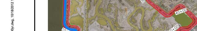
22 Civil and Cost Appendix Watersheds Drainage Area [ac] Pilot Channel Invert Elevation [ft NAVD] Pilot Channel Top Width* [ft] Pilot Channel Length** [ft] Pilot Channel End Const. Year Pond A Pond A Ponds A , North A Central A Southwest A East A * Top Width at EL 7.5 feet NAVD88 **Length assumes that 50 feet from outboard levee crest is excavated as part of the outboard levee breach 3.0 Locally Preferred Plan 3.1 Flood Risk Management Levees The LPP involves the construction of FRM levees at a 100-year LOP (1% ACE) along with a medium fill ecotone built to a 30:1 slope in Pond A18 only. Pond restoration measures as detailed above are included in the LPP for Pond A18 only. The LPP is summarized in Table 7 Locally Preferred Plan Summary and the following sections. Table 7. Locally Preferred Plan Summary Section Station Range Side Slopes (H:V) Average Height (including settlement) (ft.) Crown Width (ft.) Wick Drains? 30:1 Ecotone? Sec to : No Yes Sec to : No No Sec to : Yes No Sec to : Yes Yes Sec to : No Yes Alignment The Locally Preferred Plan includes an Alviso North, WPCP South alignment with a closure structure across Artesian Slough. On the Alviso side, levees would be constructed from STA 0+00 at existing high ground West of Alviso along the existing dikes bordering ponds A12, 13, and 16. The levees will tie into a new tide gate north of the Don Edwards Center at Artesian Slough (reference drawings) at approximate STA On the WPCP side, new levees will be constructed from the tide gate, along the existing dikes of Pond A18, and will tie into the existing levees at Coyote Creek north of the WPCP sludge ponds at STA (Sheets C-01 to C-54, LPP Plans, Profiles and Sections). USACE San Francisco District South San Francisco Bay Shoreline Phase I Study September 2015 E1-20
23 Civil and Cost Appendix Design, Considerations, and Construction The levee will be built to the elevations shown in Table 7 to achieve a post-settlement design elevation of feet. Fill quantities and resultant construction costs reflect an overbuilt cross-section. Settlement was estimated using Figure 3-1 of the Geotechnical Appendix. The thickness of Bay Mud transitions gradually along the levee alignment (< 1-foot / 100-linear feet) suggesting that regrading of the post-settlement levee cross-section will not be necessary. The levee side slopes will be 3H:1V and the crown will be 16 feet wide. A 12-foot wide levee crest access road will be constructed of 6-inch thick gravel. Turnarounds on each side of the railroad gate (STA 43+75) and one turnout at STA will be constructed. Construction activities include clearing and grubbing and stripping of work areas including the permanent and temporary construction easement. Hydroseeding is included for erosion protection along finished grades. Foundation preparation for the new levee will include degrading the existing levee to elevation 0 ft and excavating an inspection trench along the centerline of the levee. The inspection trench will be 4 feet deep with 1:1 side slopes and have a bottom width of 8 feet. All excavation is assumed to have a 50% fill suitable for re-use on the new levees. Excess cut would be stored onsite for the construction of the ecotone. The deep Bay Mud will also require the use of wick drains during construction to hasten time to consolidate and increase strength of foundation soils. Wick drains will have 6-foot mid point spacing. Wick drains will extend approximately 5 feet beyond the levee crest and 5 feet deeper than the lower extent of the Bay Mud. Corrugated conduit will span horizontally across the levee footprint and be attached to each wick drain to drain the water. Wick drains will be required from approximately STA to The design basis for requiring wick drains is related to the thickness of Bay Mud (i.e. > 10 feet) and the height of new fill (i.e. > 10 feet) being constructed (Geotechnical Appendix). Erosion protection for the new levee will be provided by vegetation on the water and landside slopes. Flood water surface elevations are relatively static in the project area due to existing topographic features and prevailing wind direction. Therefore, vegetation alone was judged sufficient for providing erosion protection. In addition to the vegetation, ecotone fill (STA 0+00 to and STA to ) provides a substantial buffer between erosive forces and the levee prism for the full design height. Existing berms and islands serve to dissipate wave energy in the managed pond adjacent to the levee from STA to Closure Structures Railroad Closure Flood Gate The railroad structure at STA would be a mitre leaf swing gate measuring approximately 50 feet x 12 feet and constructed to an elevation of 16 feet. The structure would be supported 1 Following development of the final array of alternatives, determination of the design water surface (and top of levee) was refined and revised. The 100-year LOP levee elevations for the LPP are therefore different than the 100- year elevations of the final array. USACE San Francisco District South San Francisco Bay Shoreline Phase I Study September 2015 E1-21
24 Civil and Cost Appendix on a concrete pile deep foundation system to transfer loads through the soft Bay Mud strata to stiff foundation soils. A concrete cutoff will be installed beneath the gate to prevent through seepage in the railroad bed beneath the gate. The cutoff will extend 5 feet below the bottom of each gate leaf. The selected closure would be operated manually and coordinated with local authorities and the railroad in anticipation of a flood. Manual operation minimizes the risk of mis-operation on an active railroad at the risk of not being closed during a tidal flood event. Not closing the gate would result in limited flooding but would not induce additional failure modes along other FRM features Artesian Slough Closure Tide Gate The Artesian Slough closure at STA would consist of a concrete headwall measuring approximately 100 feet x 20 feet and constructed to an elevation of 16 feet. The structure would include two 72-inch discharge pipes to release flow from Artesian Slough. The pipes will include gates capable of both allowing normal tidal exchange to, and preventing flood water from entering into, the slough. The structure would be supported on a concrete pile deep foundation system to transfer loads through the soft Bay Mud strata to stiff foundation soils. The selected closure would be operated passively and/or automatically to minimize disruptions to normal tidal fluctuations and ensure closure occurs ahead of, and during, flood events. 3.3 Ecosystem Restoration Transitional Habitat Alignment The ecotone alignment would generally follow the levee alignment and be constructed on and adjacent to the waterside slope of the new FRM levee. The extent of ecotone in the western reach of the alignment is within Pond A12 and 13 from STA 0+00 to 43+80, and in the eastern reach of the alignment within Pond A18 from STA to (Sheets C-01 to C-54, LPP Plans, Profiles and Sections) Design, Consideration, and Construction The ecotone will be constructed to an elevation of 15.2feet at its interface with the waterside slope of the new levee under the LPP. The ecotone will have a 30:1 slope which transitions to a 3:1 slope at approximately elevation 5 feet. Hydroseeding and plantings are included for erosion protection. The ecotone would be constructed with excess cut or waste material nonsuitable for levee fill and no cost fill generated by local construction/maintenance projects identified by the non-federal sponsor Pond/Tidal Marsh Restoration Pond Restoration will occur under the LPP. Pond restoration will include a series of inboard and outboard dike breaching, construction of pilot channels, temporary heightening of inboard levees, and the construction of ditch blocks to block currently existing channels in restored ponds. The pond restoration measures will be constructed as detailed above in Section 2.2. USACE San Francisco District South San Francisco Bay Shoreline Phase I Study September 2015 E1-22
25 Civil and Cost Appendix Construction will utilize fill available onsite, such as fill from existing berms, and any dredging that may occur. 4.0 National Economic Development Plan 4.1 Flood Risk Management Levees The NED Plan involves the construction of FRM levees built to an elevation containing the 25- year flood event along with the no fill Ecosystem Restoration alternative 50-foot wide bench. Pond restoration measures as detailed above are also included in the NED Plan. The NED Plan is summarized in the table below and the following sections. Table 8. National Economic Development Plan Summary Section Station Range Side Slopes (H:V) Average Height (including settlement) (ft.) Crown Width (ft.) Wick Drains? 50-foot Bench? Sec to : No Yes Sec to : No No Sec to : Yes No Sec to : Yes Yes Sec to : No Yes Alignment The NED Plan includes an Alviso North, WPCP South alignment with a closure structure across Artesian Slough. On the Alviso side, levees would be constructed from STA 0+00 at existing high ground West of Alviso along the existing dikes bordering ponds A12, 13, and 16. The levees will tie into a new tide gate north of the Don Edwards Center at Artesian Slough (reference drawings) at approximate STA On the WPCP side, new levees will be constructed from the tide gate, along the existing dikes of Pond A18, and will tie into the existing levees at Coyote Creek north of the WPCP sludge ponds at STA (See Sheets C-01 to C-54, NED Plans, Profiles and Sections) Design, Considerations, and Construction The levee will be built to the elevations shown in Table 8 to achieve a post-settlement design elevation of 12.5 feet. Fill quantities and resultant construction costs reflect an overbuilt cross-section. Settlement was estimated using Figure 3-1 of the Geotechnical Appendix. The thickness of Bay Mud transitions gradually along the levee alignment (< 1-foot / 100-linear feet) suggesting that regrading of the post-settlement levee cross-section will not be necessary. The levee side slopes will be 3H:1V and the crown will be 16 feet wide. A 12-foot wide levee crest access road will be constructed of 6-inch thick gravel. Construction activities include clearing and grubbing and stripping of work areas including the permanent and temporary construction easement. Hydroseeding is included for erosion protection along finished grades. Foundation preparation for the new FRM levee will include degrading the existing levee to elevation 0 ft and excavating an inspection trench along the USACE San Francisco District South San Francisco Bay Shoreline Phase I Study September 2015 E1-23
26 Civil and Cost Appendix centerline of the levee. The inspection trench will be 4 feet deep with 1:1 side slopes and have a bottom width of 8 feet. All excavation is assumed to have a 50% fill suitable for re-use on the new levees. Excess cut would be stored onsite for the construction of the ecotone. The deep Bay Mud will also require the use of wick drains prior to and during construction to reduce settlement time and strengthen soil to increase the rate of construction. Wick drains will have 6-foot mid point spacing. Wick drains will extend approximately 5 feet beyond the levee crest and 5 feet deeper than the lower extent of the Bay Mud. Corrugated metal piping will span horizontally across the levee footprint and be attached to each wick drain to drain the water. Wick drains will be required from approximately STA to The design basis for requiring wick drains is related to the thickness of Bay Mud (i.e. > 10 feet) and the height of new fill (i.e. > 10 feet) being constructed (Geotechnical Appendix). Erosion protection for the new levee will be provided by vegetation on the water and landside slopes. Flood water surface elevations are relatively static in the project area due to existing topographic features and prevailing wind direction. Therefore, vegetation alone was judged sufficient for providing erosion protection. In addition to the vegetation, the 50 foot bench (STA 0+00 to and STA to ) provide a substantial buffer between erosive forces and the levee prism below elevation 9 feet and helps to dissipate remaining wave energy above elevation 9 feet. Existing berms and islands serve to dissipate wave energy in the managed pond adjacent to the levee from STA to Closure Structures Railroad Closure Flood Gate The railroad structure at STA would be a mitre leaf swing gate measuring approximately 50 feet x 12 feet and constructed to an elevation of 16 feet. The structure would be supported on a concrete pile deep foundation system to transfer loads through the soft Bay Mud strata to stiff foundation soils. A concrete cutoff will be installed beneath the gate to prevent through seepage in the railroad bed beneath the gate. The cutoff will extend 5 feet below the bottom of each gate leaf. The selected closure would be operated manually and coordinated with local authorities and the railroad in anticipation of a flood. Manual operation minimizes the risk of mis-operation on an active railroad at the risk of not being closed during a tidal flood event. Not closing the gate would result in limited flooding but would not induce additional failure modes along other FRM features Artesian Slough Closure Tide Gate The Artesian Slough closure at STA would consist of a concrete headwall measuring approximately 100 feet x 20 feet and constructed to an elevation of 16 feet. The structure would include two 72-inch discharge pipes to release flow from Artesian Slough. The pipes will include gates capable of both allowing normal tidal exchange to, and preventing flood water from entering into, the slough. The structure would be supported on a concrete pile deep foundation system to transfer loads through the soft Bay Mud strata to stiff foundation soils. USACE San Francisco District South San Francisco Bay Shoreline Phase I Study September 2015 E1-24
27 Civil and Cost Appendix The selected closure would be operated passively and/or automatically to minimize disruptions to normal tidal fluctuations and ensure closure occurs ahead of, and during, flood events. 4.3 Ecosystem Restoration Transitional Habitat Alignment The 50 foot bench alignment would generally follow the levee alignment. It would be constructed along the western side of the alignment at Pond A12, 13, and 16 from STA 0+00 to as well as along pond A18 from STA to (See Sheets C-01 to C-54, NED Plans, Profiles and Sections) Design, Consideration, and Construction The bench will be constructed to an elevation of 9 feet. The bench will span 50 feet before transitioning to a 3:1 slope to meet existing grade. Hydroseeding and plantings are included for erosion protection. The bench and restoration would be constructed with cut material from the degradation of the existing levee and levee foundation excavation that is non-suitable for levee fill Pond/Tidal Marsh Restoration Pond Restoration will occur under the Locally Preferred Plan. Pond restoration will include a series of inboard and outboard levee breaching, construction of pilot channels, temporary heightening of inboard levees, and the construction of ditch blocks to block currently existing channels. The pond restoration measures will be constructed as detailed in Section 2.2. Construction will utilize fill available onsite, such as fill from existing berms, and any dredging that may occur. 5.0 Recreation Mitigation 5.1 Bridges Both the NED and LPP will require mitigation for recreation facilities currently in place in the project area. To provide access for cyclists, joggers, etc., the levees will require bridges at the rail road and Artesian Slough closures. The bridge at the railroad crossing will span approximately 380 feet with a width of 12 feet. The bridge at the Artesian Slough crossing will span approximately 100 feet with a width of 12 feet. Representative details for the rail road bridge are shown in Sheets D-05 and D-06 of the NED and LPP Plans, Profiles and Sections. Representative details for the Alviso Slough crossing are shown on Sheets D-02 to D-04 of the NED and LPP Plans, Profiles and Sections. Typical bridge construction has been assumed for the purposes of this study, as in-depth consideration of use, capacity, and architectural requirements will need to be determined during the pre-construction engineering and design (PED) phase. Quantity development and assumptions are further discussed in Section 8.0. USACE San Francisco District South San Francisco Bay Shoreline Phase I Study September 2015 E1-25
28 Civil and Cost Appendix 5.2 Bay Trails For both the NED and LPP, existing recreational trails will require reconstruction and improvement due to FRM and ER construction. Bay trails will be designed to CalTrans standards (Highway Design Manual Chapter 1000, Bicycle Transportation Design) as Class I Bikeways. The recreational trails will be a total length of approximately 22,000 feet long. They will be constructed to a paved width of 10 feet with 3 foot shoulders of all-weather material (total width of 16 feet). For this study, it is assumed compacted dirt is sufficient for this purpose. Clearing and grubbing will occur over the work area, including the 16 food wide trail and 10 foot easements on either side for construction. Stripping will occur over the entire 16 foot width of the trail. 6.0 Real Estate For the Locally Preferred Plan, acquisition of approximately 900 acres currently owned by the City of San José are allocated to ecosystem restoration, with approximately 54 acres for levee easements, 7 acres of permanent road easements, and 52 acres of temporary work easements. These acquisitions are currently split with approximately 31 parcels, more or less. The non- Federal sponsor is responsible for procurement of all lands, easements, relocations, rights-ofway, and disposal areas (LERRDs) that are necessary for construction, operation, and maintenance of the project. Potential real estate needs are described in the following sections. 6.1 Easements and R/W Requirements Maintenance easements will be required for the proposed project. Levee maintenance and inspection will likely be performed from toe of the proposed levee, but may be accomplished from the levee crown. Fifteen feet from the landside toe of proposed levee has been designated as maintenance (permanent) easement. In addition to maintenance easements, utility relocation may require easement acquisition, depending on the placement of the relocated utilities and overhead/underground utilities. Temporary construction easements will also be required for this project, and have been assumed to be 15 additional feet beyond the limits of the maintenance easement. In areas where the landside toe of the proposed levee lands within existing structures or property, there may be an opportunity to minimize required temporary easements by performing construction activities on the levee crown. For the purposes of this study, in areas where there was minimal infringement of temporary easement on existing property/structures, the temporary easement was reduced in width. This variance will require further investigation during final design. Permanent and temporary construction easements are detailed on Sheets C-01 through C-20 of the NED and LPP Plans, Profiles and Sections USACE San Francisco District South San Francisco Bay Shoreline Phase I Study September 2015 E1-26
29 Civil and Cost Appendix 6.2 Borrow Locations Borrow material from sources other than what will be derived from the degradation of existing levees is required to complete the levee construction. The sponsor will be required to provide 960,000 cubic yards of borrow to construct the LPP FRM levee. The borrow is anticipated to require approximately 54 acres at the identified borrow sites; Upper Llagas Creek, Upper Guadalupe River and Permanente Creek. Upper Llagas Creek is the borrow site that is the furthest from the Shoreline project at 30 miles one-way. For cost estimating purposes, it was conservatively assumed that all levee borrow will be delivered via a 60 mile round trip. Upper Llagas Creek and Upper Guadalupe River are active USACE projects for which the sponsor is required to obtain the necessary real estate, and would be eligible to receive credit under LERRDs for the respective federal projects. Permanente Creek is a non-federal project requiring a borrow easement for approximately 22 acres, and would be eligible to receive credit under LERRDs for the South San Francisco Bay Shoreline Project. The non-federal sponsor will secure sufficient fill to substantially construct restoration features prior to the initiation of construction. It is assumed this restoration fill will be placed within the project boundaries, and will have no purchase cost. Costs to cover rehandling of stockpiled materials and construction of restoration fills have been included in the LPP cost estimate. 6.3 Disposal and Storage Area There is no need for disposal areas. All material that cannot be used as levee fill will be used as common fill within the project footprint. Common fill is expected to be used for construction of the bench (NED) and/or ecotone (LPP). No excess material is anticipated that would require on-site storage or that would require off-site disposal. 6.4 Staging Area Potential staging areas have been identified around the project site for the NED and LPP alternatives. Due to the use of the same alignment, staging areas are the same for both plans (Sheet G-03, NED and LPP Plans, Profiles and Sections). 7.0 Relocations and Modifications 7.1 Overview In total, there are over 80 known utilities within the study area that may be impacted by construction of flood risk management and environmental restoration features. Only four utility crossings are known to cross the alignment of the new flood control levee alignment. Utilities operated by the WPCP comprise of a large portion of the existing utilities potentially impacted. The WPCP owns approximately 61 of the more-than 80 utilities in the area. The majority of the WPCP s 61 known utilities in the project area are sited along both sides of Artesian Slough between the WPCP and the Don Edwards Center. Storm drains, sanitary sewers, and other utilities potentially conflict on the west and east side of Alviso and along USACE San Francisco District South San Francisco Bay Shoreline Phase I Study September 2015 E1-27
30 Civil and Cost Appendix Grand Blvd. These utilities are described in the Existing Utilities Information Technical Memorandum dated 29 September 2011 (Appendix A). 7.2 LPP and NED Due to the same alignment, utility relocation/modification needs for the NED and LPP are identical. The utility relocation and modifications that apply to the NED and LPP alignment are summarized below: A siphon near STA was installed in 2012 and maintains flow through the existing inboard dike to New Chicago Marsh. The siphon will be modified to allow for means of positive closure during flood events. Approximately 685 feet of an underground electrical supply leading to the SCWD weir at approximately STA will need to be relocated to an overhead configuration. A culvert near STA that maintains flow from Artesian Slough to a small mitigation area near the southwest extent of Pond A18. The culvert will be replaced to maintain existing functionality and include a means of positive closure during flood events. 5 existing PG&E power towers run through Pond A18 and may require in-place erosion protection due to potential changes in hydraulics caused by levee, ecotone, bench, or pond restoration construction. Overhead clearance of the new levee (STA ) is substantial enough to not impact levee construction. The existing rail road bridge to the north of the project will require approximately 8,400 tons of rock protection due to potential changes in hydraulics caused by levee, ecotone, bench, or pond restoration construction. 8.0 Development of Construction Quantities 8.1 Levee and Transitional Habitat Quantities Quantities were developed at a feasibility level of design for each alternative. Quantities were based on output from Autodesk Civil3D as well as typical cross sections determined from average levee heights and design geometry. Imported fill for levee construction is assumed to be within 30 miles of the levee alignment based on the furthest of the three fill sources (i.e. Upper Llagas Creek) identified in Section 6. Hand calculation sheets including geometry and sample calculations are found in Figures Fill volumes include settlement. Build to elevations (i.e. fill heights) for the LPP and NED levees are shown in the plan set for each levee. Quantities for the NED levees and bench are found in Quantities Tables 1 respectively, LPP levees and ecotone in Quantities Tables 2. USACE San Francisco District South San Francisco Bay Shoreline Phase I Study September 2015 E1-28
31 Civil and Cost Appendix 8.2 Pond Restoration Quantities Autodesk Civil3D developed cross-sections and aerial topography (LiDAR) of the majority of the salt ponds within the Shoreline Study area were used to develop quantities. Areas in which there was no LiDAR available, assumed values for levee geometry were used. Hand calculation sheets including geometry and sample calculations are included in Figures Pond restoration quantities are found in Quantities Recreation Mitigation Quantities Bay Trail Quantities Quantities were developed based on a typical cross section. It was assumed that the Bay Trail would have a 10-foot paved width with 3-foot compacted dirt shoulders per CalTrans standards. Hand calculations are found in Figure 32. Bay Trail Quantities are found in Quantities Bridge Quantities Bridge quantities were developed based on a March 2006 Feasibility Report titled Alviso Slough Pedestrian Bridge Feasibility Study, Bay Trail Reach 9B, developed by CH2MHILL for the City of San Jose Department of Parks, Recreation and Neighborhood Services 2. Quantities for the pedestrian bridges in this report were scaled based on length to become a representative sample of the pedestrian bridges included in the Shoreline Project, acceptable for cost estimating purposes. Bridge restoration quantities are found in Quantities Cost Estimates Construction costs was developed using MII (MCACES) software and is summarized in Table 9. Costs for each applicable element include 27% for contingency for the NED/NER and 26% contingency for the LPP. The contingency was originally developed at the 2013 Cost and Schedule Risk Assessment and refined in the spring of Table 9. Project First Cost Summary Element NED/NER LPP Real Estate $13,392,000 $13,493,000 FRM Features $55,402,000 $67,299,000 Bank Stabilization $1,535,000 $1,523,000 Utility Relocations $587,000 $587,000 Transitional Habitat $0 $35,944,000 Pond Restoration $5,765,000 $5,765,000 2 The Alviso Slough Pedestrian Bridge was identified by the non-federal sponsors as a suitable go-by for estimating for the Shoreline Study. USACE San Francisco District South San Francisco Bay Shoreline Phase I Study September 2015 E1-29
32 Civil and Cost Appendix Recreation $4,848,000 $4,848,000 Preconstruction Engineering and Design $15,071,000 $24,842,000 Construction Management $7,440,000 $12,327,000 Monitoring $984,000 $984,000 Adaptive Management $6,276,000 $6,276,000 Total $111,300,000 $173,900, Value Engineering A Value Engineering (VE) study, sponsored by the Corps and facilitated by Value Management Strategies, Inc., was conducted for the Shoreline Study in Sacramento, California April 2-5, The VE study evaluated the initial array of FRM options (FRM Options 1A through 4), with the objective of confirming the process by which the PDT arrived at the array of alternatives, and to make recommendations for improving the design and evaluation of alternatives. The Revised draft Value Engineering Report, dated May 3, 2012, and provided the following statement of concurrence: Based on the information provided, it appears that the Project Delivery Team (PDT) considered an adequate range of alternatives and the process used to arrive at the array of alternatives (Options 1A, 1B, 1C, 2, 3, 4, and non-structural) 3 is reasonable. The VE study developed six alternatives for consideration by the PDT. The purpose of the six alternatives was to reduce project cost, reduce implementation schedule, and/or improve project performance. A summary of the recommended alternatives along with the PDT response is provided below. 1.1 Select Option year as the final alignment; eliminate wick drains; reuse existing levees; do not remove them, just raise them with earth Final plan selection will be based on the NED analysis and non-federal sponsor preference. The elimination of wick drains will require additional analyses during the PED phase. While eliminating wick drains is technically feasible (based on known conditions), the time required to construct without eliminating pore pressure as a significant negative impact on the short-term level of protection. If during the PED phase additional investigations and analyses indicate that the existing levees are suitable foundation for additional fill, they can be left in place. 3 At the time the VE team reviewed the array of options, only the seven FRM options had been formulated. Subsequent to completion of the VE study, through coordination with the non-federal sponsors, four additional FRM options were added to the final array, as discussed in Section 2.1. USACE San Francisco District South San Francisco Bay Shoreline Phase I Study September 2015 E1-30
33 Civil and Cost Appendix 1.2 Select Option year as the final alignment; eliminate wick drains; reuse existing levees; do not remove them, just raise them using precast concrete units Final plan selection will be based on the NED analysis and non-federal sponsor preference. The elimination of wick drains will require additional analyses during the PED phase. While eliminating wick drains is technically feasible (based on known conditions), the time required to construct without eliminating pore pressure as a significant negative impact on the short-term level of protection. Although the overall weight may be reduced by concrete, the bay mud is highly compressible and even small increases in stress over the existing stress condition may cause significant settlement and the need for wick drains may not be eliminated. The seepage risks may be increased by allowing a higher head on the existing levee without increasing the seepage path length. The reliability of the levee may not be improved significantly when compared to the existing levee fragility analysis. Higher reliability is a primary goal of the project so that damages are reduced. Differential settlement that may result as of construction sequencing and foundation differential bay mud thickness could result in differing crest elevations and preferred flood overtopping locations and would be difficult to re-grade to a uniform crest elevation. 1.3 Construct geofoam block core levees; eliminate wick drains EPS block is a common practice in general soft ground construction (highway embankments, etc), not levee construction. Should the fill over the blocks become damaged or eroded the buoyancy resistance would be reduced, compounding an erosion problem into potential other problems. This recommendation can, however, be examined further during PED phase. 2.0 Limit crown width to 10 feet While this is a valid potential way to reduce cost, it is quite common for levee crest widths to exceed 10 feet. Below are a few examples of levees with crest widths greater than 10 feet. Feather River near Arboga, CA Truckee Irrigation Canal Levee, near Fearnly, NV Jones Track Levee near Stockton, CA Natomas Levees near Sacramento, CA Winslow Levees, near Winslow AZ Guadalupe River Levees, near Alviso, CA Coyote Creek Levees, near San Jose/Alviso, CA San Mateo Bay Front Levees, San Mateo, CA Roaring Sough Levee, CA Crest Width: 20 ft Crest Width: 15 ft Crest Width: 28 ft Crest Width: 20 to 44 ft Crest Width: 22 ft Crest Width: 20 ft Crest Width: 18 ft Crest Width: 12 to 18 ft Crest Width: 30 ft A performance change in reducing the crest width may include decreased flexibility if levee settles too much or sea level rise exceeds expectations (1-foot raise at 3:1 slopes would reduce the crest to 10 ft), and that emergency access and flood fighting would be reduced. USACE San Francisco District South San Francisco Bay Shoreline Phase I Study September 2015 E1-31
34 Civil and Cost Appendix Additionally, loss of levee fill width would lead to shorter time for erosion to breach levee should erosion initiate. 3.0 Do not gravel top the levees; no vehicular access The levee could become impassible during wet weather, making emergency access and flood fighting more difficult and could reduce levee performance. Levee surfaces now on the outer levees are not graveled and even during small rain events, light trucks are unable to pass the levee crest safely. The non-federal sponsor has suggested a preference for gravel surfacing. 4.0 Consider a 12-hour-per-day construction operation to improve the schedule Where the construction schedule is not controlled by the rate of foundation consolidation, this is a reasonable and effective method to reduce the overall construction schedule. This recommendation should be considered during PED phase. USACE San Francisco District South San Francisco Bay Shoreline Phase I Study September 2015 E1-32
35 Civil and Cost Appendix This page intentionally left blank. USACE San Francisco District South San Francisco Bay Shoreline Phase I Study September 2015 E1-33
36 Figures USACE San Francisco District South San Francisco Bay Shoreline Phase I Study September 2015 E1-34
37 USACE San Francisco District South San Francisco Bay Shoreline Phase I Study September 2015 E1-35


38 Appendix E1 - Civil Design Figure 1 Shorelie Study Area E1-36


39 E1-37


40 E1-38


41 E1-39


42 E1-40


43 E1-41


44 E1-42


45 Appendix E1 - Civil Design E1-43


46 Appendix E1 - Civil Design E1-44


47 Appendix E1 - Civil Design E1-45


48 Appendix E1 - Civil Design E1-46


49 Appendix E1 - Civil Design E1-47


50 Appendix E1 - Civil Design Figure 13A. Pond Restoration 2020 E1-48


51 Appendix E1 - Civil Design Figure 13B. Pond Restoration 2025 E1-49


52 Appendix E1 - Civil Design Figure 13C. Pond Restoration 2030 E1-50
53 Levee Fill (yd 3 /ft) = {Inspection Trench ft 3 /ft + [16H + 3H(H)]} / 27 Figure 14 Levee Volume Sample Calculations E1-51
54 50-ft Bench (yd 3 /ft) = 9ft * 50ft = 450ft 3 /ft ~ 16.7 yd 3 /ft Ecotone (yd 3 /ft) = {(0.5 * 5 ft * 3 * 5 ft) + [5 ft * 30 * (15.2 5) ft] + [0.5 * (15.2 5) ft * 30 * (15.2 5) ft]} [50-ft Bench * 15.2 ft * 3 *15.2 ft] = [ ] [ ] = = ft 3 /ft ~ 86.4 yd 3 /ft Figure 15 Transitional Habitat Fill Sample Calculations E1-52
55 Degrade of existing levee (yd 3 ) = 2010 LiDAR Surface at EL 0 ft (Surface calculation in Autodesk Civil3D) Inspection Trench (yd 3 /ft of levee) = 8 ft * 4 ft + 4 ft * 4 ft = 48 ft 3 /ft ~ 1.8 yd 3 /ft Figure 16 Existing Levee and Foundation Excavation Sample Calculations E1-53
56 E1-54
57 E1-55
58 E1-56
59 E1-57
60 E1-58
61 E1-59
62 E1-60
63 E1-61
64 E1-62
65 E1-63
66 E1-64
67 E1-65
68 E1-66
69 E1-67
70 Quantity Tables E1-68
71 E1-69
72 Qunatities 01 - South San Francisco Bay Shorline - NED Levee Quantities 12.5 ft Levee Height with 50 ft Wide Bench Project Station Reach Begin End Length Height (ft) (ft) Fill (CY) , , , , , , , , , ,510 Project Station Reach Begin End Length (ft) Degrade Cut (CY) Inspection Trench TOTAL Levee Fill (CY) 50-ft Bench Turnout 50% Cut 50% Cut 50% Cut Compacted Obtain Offsite Borrow Place & Compact ,380 60,807 7,787 68, ,522 73, ,297 34,297 27, , , ,120 37,795 3,769 41,564 63, ,782 20,782 16,626 47,603 64, ,975 64,381 5,289 69, , ,835 34,835 27,868 90, , , ,817 9, , ,363 92, ,320 82,320 65, , , , ,712 8, , ,998 79, ,601 86,601 69,280 60, ,998 E1-70
73 Quantities 02 - South San Francisco Bay Shorline - LPP Levee Quantities 15.2 ft Levee Height with 30:1 Ecotone Project Station Reach Begin End Length Height (ft) (ft) Fill (CY) , , , , , , , , , ,590 Levee Only Project Station Cut (CY) Fill (CY) Reach Begin End Length (ft) Degrade Inspection Trench TOTAL Levee 50-ft Bench Turnout Ecotone 50% Cut 50% Cut 50% Cut Compact Obtain Offsite Borrow Place & Compact ,380 60,807 7,787 68, ,859 73, ,228 34,297 34,297 27, , , ,120 37,795 3,769 41,564 90, ,782 20,782 16,626 74,502 91, ,975 64,381 5,289 69, , ,835 34,835 27, , , , ,817 9, , ,566 92, ,102 82,320 82,320 65, , , , ,712 8, , ,079 79, ,337 86,601 86,601 69, , ,079 E1-71
74 South San Francisco Bay Shoreline Study - Quantities LPP year (1%) Level of Protection Pond Restoration Quantities - Outboard Levee Breaches Watershed Existing Top Elevation (ft.) Levee Toe Elevation (ft.) Existing Levee Side Slopes (H:V) Existing Levee Top Width (ft.) Existing Levee Bottom Width (ft.) Breach top Existing Top Elevation Breach Invert Elevation (ft.) Breach Top EL 7.5 Breach XS EL 7.5 Breach Bottom Width (ft.) Breach Slopes (H:V) Excavation Volume Breach of Levee Only (CY) Cross Sectional Area of Breach Extension (SF) Total Extension Length (ft.) Excavation Volume (CY) Pond A12 (1) (A11 in memo) , ,400.9 Pond A12 (2) , , ,249.8 Phase 1 Total: , ,650.8 Pond A9* , , ,822.2 West Pond A9* , , ,822.2 Pond A10* , ,456.0 Pond A10West* , ,456.0 North A , ,146.4 Central A , ,739.8 West A , ,604.8 East A , , ,120.3 Southwest A , ,604.8 South A , ,604.8 Phase 2 Total: , ,167.9 Pond A , , , ,277.7 Phase 3 Total: , ,277.7 *Values for these ponds are assumed due to lack of topographical data MHHW: 7.5 Note: Phase 1 Construction: Phase 2 Construction: Phase 3 Construction: E1-72
75 South San Francisco Bay Shoreline Study - Quantities LPP year (1%) Level of Protection Pond Restoration Quantities - Internal Berm Breaches Watershed Number of Breaches Existing Top Elevation (ft.) Levee Toe Elevation (ft.) Existing Levee Side Slopes (H:V) Existing Levee Top Width (ft.) Existing Levee Bottom Width (ft.) Breach top Existing Top Elevation (ft.) Breach Invert Elevation (ft.) Breach Top EL 7.5 (ft.) Breach XS EL 7.5 (SF) Breach Bottom Width (ft.) Breach Slopes (H:V) Volume of Excavation of Breach of Levee Only (CY) Cross Sectional Area of Breach Extension (SF) Total Extension Length (ft.) Volume of Breach Extension (CY) Excavation Volume (CY) Pond A9/A14* , ,021.6 A12/A11* , , ,194.1 Phase 1 Total: , ,215.8 Pond A10/A11* , , ,182.8 Phase 2 Total: , ,182.8 Pond A ,963.3 Phase 3 Total: ,963.3 *Values for these ponds are assumed due to lack of topographical data MHHW: 7.5 Note: Phase 1 Construction: Phase 2 Construction: Phase 3 Construction: E1-73
76 South San Francisco Bay Shoreline Study - Quantities LPP year (1%) Level of Protection Pond Restoration Quantities - Pilot Channels Watershed Pilot Channel Levee Toe Invert Elevation (ft.) Elevation (ft.) Pilot Channel Pilot Channel Top Slopes (H:V) EL 7.5 (ft.) Pilot Channel Bottom Width (ft.) Pilot Channel XS EL 7.5 Pilot Channel XS Grade (SF) Length of Pilot Channel (ft.) Exavation Volume (CY) Pond A12 (1) (A11 in memo) ,305.6 Pond A ,184.0 Phase 1 Total: ,489.6 Pond A9* , , ,264.4 West Pond A9* , , ,264.4 Pond A10* ,178.9 Pond A10West* ,466.7 North A Central A ,708.3 West A ,814.8 East A ,869.4 Southwest A Phase 2 Total: , ,824.3 Pond A , , , ,406.9 Phase 3 Total: , ,406.9 *Values for these ponds are assumed due to lack of topographical data MHHW: 7.5 Note: Phase 1 Construction: Phase 2 Construction: Phase 3 Construction: E1-74
77 South San Francisco Bay Shoreline Study - Quantities LPP year (1%) Level of Protection Pond Restoration Quantities - Ditch Blocks Pond Number of Ditch Blocks Top Elevation (ft.) Toe Elevation (ft.) Side Slopes (H:V) Top Width (ft.) XS Area (SF) Approx. Avg Length (ft.) Volume per Block (CY) Required Fill (CY) Bank Run (CY) Pond A12 (1) (A11 in memo) Pond A12 (2) , , , ,289.4 Phase 1 Total: , ,240.2 Pond A Pond A Pond A , ,617.8 Pond A18 North Pond A18 Central Pond A18 Southwest , , , ,129.4 Pond A18 East , , , ,810.9 Phase 2 Total: , ,580.3 Pond A Pond A , ,605.8 Pond A , ,613.3 Phase 3 Total: , ,551.0 *Values for these ponds are assumed due to lack of topographical data Note: Phase 1 Construction: Phase 2 Construction: Phase 3 Construction: E1-75
78 South San Francisco Bay Shoreline Study - Quantities LPP year (1%) Level of Protection Pond Restoration Quantities - Internal Berm Interim Raising Pond Length (ft.) Existing Top Elevation (ft.) Levee Toe Elevation (ft.) Existing Levee Top Width (ft.) Existing Levee Bottom Width (ft.) Exisitng Levee Slopes (H:V) Existing Levee XS Area (SF) Proposed Top Elevation (ft.) Proposed Top Width (ft.) Proposed Slope (H:V) Proposed XS Area (SF) Existing Levee Volume (CY) Proposed In- Place Volume (CY) Required Borrow (CY) Pond A12 North & Northwest 4, , , , ,045.6 Phase 1 Total: 4, , , , ,045.6 Pond A9 East* 3, , , , ,477.9 Pond A11 North and East* 4, , , , ,105.2 Phase 2 Total: 8, , , , ,583.1 *Values for these ponds are assumed due to lack of topographical data **Existing berm geometry provides for a larger cross sectional area despite the shorter berm height. Exacation Volume is for reshaping of the existing berm. Note: Phase 1 Construction: Phase 2 Construction: Phase 3 Construction: Difference in Geometry Volume (CY) Excavation Volume (CY)** E1-76
79 South San Francisco Bay Shoreline Study - Restoration Quantities Bay Trails Recreation Mitigation Length Paved Width (ft) Compacted Dirt Shoulder, Width (each side, ft) Total Width (ft) Aggregate Base (CY) Asphault Concrete (CY) Clearing and Grubbing (AC) Stripping (CY) 12, , ,229.6 E1-77
80 South San Francisco Bay Shoreline Study - Restoration Quantities Alviso North WPCP South, 100-YR Pedestrian Bridges Reach Length (ft) Excavation (Bridge) (CY) Excavation (Type D) (CY) Excavation (Retaining Wall) (CY) Backfill (Bridge) (CY) Backfill (Retaining Wall) (CY) 16" Steel Pipe Piling Total Length (ft) # 16" Steel Pipe Piling 48" Cast-in-Steel- Shell Piling Total Length (ft) # 48" CastinSteel-Shell Piling Concrete (CY) Box Truss Length (ft) # of Box Truss Bar Reinforcing Steel (bridge) (lb) Ornamental Railing (ft) Pedestrian Gateway Enhancements Bird Exclusion Measures Rail Road Crossing WPCP Discharge Crossing Note: These numbers are developed based on a 2006 report titled "Alviso Slough Pedestrian Bridge Feasibility Study, Bay Trail Reach 9B" prepared for the City of San Jose. Values are scaled/estimated based on overall bridge length and other factors unique to each project. These numbers are for cost estimating purposes only. E1-78
81 E1-79
82 Existing Utility Information Technical Memo Appendix E1-80
83 Technical Memorandum South San Francisco Bay Shoreline Study September 29, 2011 Reviewed by: Prepared by: Sergio Jimenez, PE Daniel Teak, EIT Under task item 3b from the Schedule of Services for South San Francisco Bay Shoreline Study dated 17 May 2011, the contractor is required to gather utility data that may be impacted by the project. The following utility information is a preliminary accounting and summary of the existing utilities in the project area that may be impacted by flood risk management features. Following identification of the NED/NER and Locally Preferred Plan, more focused utility surveys and site visit will be conducted to update the technical memo.! " # Multiple sources were used to gather information on existing utilities in the project area. They are listed and described below: Water Pollution Control Plant (WPCP) GIS Database HDR was provided with a GIS database from the City of San Jose. The database included descriptions and locations of underground utilities operated by the WPCP. This information has been summarized in Tables 1A, and 1B (Attachment 1) and has been mapped in Figures 1A, 1B, and 1C (Attachment 2). City of San Jose Utility Database ( This website was recommended for use for as a preliminary accounting of utilities. It consists of maps showing location and use of existing utilities. The information gathered from this website has been summarized in Table 2 (Attachment 1) and mapped in Figure 2 (Attachment 2). Aerial and street level photography A series of aerial and street level photography was used to identify approximate locations of utilities not identified by either of the previous databases. This information has been summarized in Table 3 (Attachment 1) and Figure 3 (Attachment 2).!"#$ E1-81
84 Technical Memorandum $ %& In total, there are over 80 known utilities that may be impacted by construction of flood control features. Utilities operated by the WPCP comprise of a large portion of the existing utilities potentially impacted. The majority of the WPCP s 61 known utilities in the project footprint are sited along both sides of Artesian Slough between the WPCP and the Don Edwards Center. A PG&E owned power line runs south through Pond A18, crosses Artesian Slough, and runs on the southern side of Grand Blvd. Storm drains, sanitary sewers, and other utilities potentially conflict on the west and east side of Alviso and along Grand Blvd.!"#$ E1-82
85 Technical Memorandum!"#$ E1-83
86 Map Label Location Diameter Material Use Status 1 Buried. East of Artesian Slough, just north of plant 6" VCP Storm Drain In-Use X 2 Buried. East of Artesian Slough to proposed tide gate. 6" STL Sulfur Dioxide Solution In-Use Originates from SO2 Bldg X 3 Buried. East of Artesian Slough to proposed tide gate. 4" PVC Sulfur Dioxide Vacuum In-Use X 4 Buried. Discharges on east side of Artesian Slough 77" x 121" RCBC Plant Effluent In-Use X 5 Above Ground, At southern tip of Artesian Slough 1" PVC Sodium Bisulfite Solution In-Use X 6 Above Ground, At southern tip of Artesian Slough 1" PVC Sodium Bisulfite Solution In-Use X 7 Buried. Discharges on east side of Artesian Slough 84" RCP Plant Effluent In-Use X 8 Buried. South of Artesian Slough. 8" -- Recycled Water Abandoned X 9 Above Ground. South of Artesian Slough. 8" DIP Recycled Water Abandoned X 10 Above Ground. South of Artesian Slough. 8" DIP Recycled Water Abandoned X Floating on Water at northen end of eastern side of artesian slough Buried. West of Artesian Slough, next to North side of Zanker Road Landfill 1.5" PVC Sulfur Dioxide Vacuum In-Use ?? RCBC Storm Drain In-Use Owner Length Notes Flexible PVC Hose to Sulfur Dioxide Induction Unit located in Outfall Channel Flows to Outfall Stormwater Pump Station, gates closed. Can flow to Artesian Slough. 13 Buried. Along West side of Artesian Slough 4" PVC Sodium Bisulfite Solution In-Use -- 2,712.7 Terminates at Plant Outfall Channel X 14 Buried. Along East side of Artesian Slough 6" PVC Sulfur Dioxide Vacuum Abandoned -- 2,614.3 Cut and Capped in 2010 as part of Alternative Disinfection Project X 15 Buried. Along East side of Artesian Slough 6" PVC Sulfur Dioxide Vacuum Abandoned X 16 Buried. Northern on east side of artesian and facility 4" PVC Sulfur Dioxide Vacuum In-Use X 17 Buried. Northern on east side of artesian and facility 4" PVC Sulfur Dioxide Vacuum In-Use X 18 Above Ground. South of Artesian Slough. 8" DIP Recycled Water Abandoned X 19 Floating on Water, ties into 2, 3, or " PVC Sulfur Dioxide Vacuum In-Use Flexible PVC Hose to Sulfur Dioxide Induction Unit located in Outfall Channel X 20 Buried. Along East side of Artesian Slough 4" PVC Sulfur Dioxide Vacuum In-Use -- 2, X 21 Buried. At southern tip of Artesian Slough 8" -- Recycled Water Abandoned X 22 Above Ground. At souther tip of Artesian Slough 1" STL Sodium Bisulfite Solution In-Use X 23 Above Ground. At souther tip of Artesian Slough 1" STL Sodium Bisulfite Solution In-Use X 24 Buried. Dischargest on southwest side of Artesian Slough 45" RCP Plant Effluent Abandoned Abandoned in 1975 X 25 Buried. Discharges on east side of Artesian Slough 84" RCP Plant Effluent Abandoned X 26 Above Ground. South of Artesian Slough. 8" -- Recycled Water Abandoned X 27 Above Ground. South of Artesian Slough. 8" -- Recycled Water Abandoned X 28 Above Ground. South of Artesian Slough. 8" -- Recycled Water Abandoned X 29 Above Ground. South of Artesian Slough. 8" -- Recycled Water Abandoned X 30 Buried. Southeast of Artesian Slough 8" -- Recycled Water Abandoned X 31 Above Ground. At southern tip of Artesian Slough 8" DIP Recycled Water Abandoned X 32 Buried. Dischargest southeast of Artesian Slough 8" DIP Recycled Water Abandoned X 33 Above Ground. At southern tip of Artesian Slough 8" DIP Recycled Water Abandoned X 34 Buried. At southern tip of Artesian Slough 8" DIP Recycled Water Abandoned X 35 Above Ground. South of Artesian Slough. 8" -- Recycled Water Abandoned X 36 Buried. South of Artesian Slough. 8" -- Recycled Water Abandoned X 37 Buried. Nothern on east side. Connects to " PVC Sulfur Dioxide Vacuum In-Use X 38 Buried. Just north of treatment plant 16" DIP Recycled Water In-Use X 39 Buried. south of Artesian slough 8" DIP Recycled Water Abandoned X 40 Above Ground. Runs north south to southeast of artesian slough 8" DIP Recycled Water Abandoned X 41 Above Ground. South of Artesian Slough. 8" DIP Recycled Water Abandoned X 42 Above Ground. South of Artesian Slough. 8" DIP Recycled Water Abandoned X 43 Above Ground. Runs north south to southeast of artesian slough 8" DIP Recycled Water Abandoned X 44 Buried, To Southeast side of Artesian Slough 1.5" PVC Sodium Bisulfite Solution In-Use Unable to find Record Drawings for this pipe. Likely goes to the Outfall X 45 Buried, To Southeast side of Artesian Slough 16" DIP Recycled Water Abandoned X Required Modification 1A 1B 1C 1D X X E1-84
87 46 Buried. Northern on east side of artesian. Connects to " PVC Sulfur Dioxide Vacuum In-Use X 47 Buried. From facility at plant connecting to " RCP Plant Effluent Abandoned X 48 Buried. Burried, connects 47 and " RCP Plant Effluent Abandoned X 49 Bured. Discharges South of Artesian Slough 48" X 76" ERCP Storm Drain In-Use X 50 Buried, along spreckles, Los Esteros, and to plant. 84" RCP Plant Effluent In-Use X 51 Buried. Runs north out of plant 4" PVC Sodium Bisulfite Solution In-Use Buried. Runs east-west in front of plant. 10" ACP Force Main In-Use City of San Jose Department of Public Works Terminates at Outfall, ran through former 6" SDV pipe when crossing under Los Esteros Rd 5, X X E1-85
88 Map Label Location Diameter Status 1 Buried, along east side of Artesian Slough -- In-Use -- 2, X 2 Buried, south of artesian, along front of plant -- In-Use X 3 Buried, front plant to 2 -- In-Use X 4 Buried, from plant to 1 2-4" Verify if Abandoned PG&E Buried, along west side of Artesian Slough?? Verify if Abandoned PG&E 1,560.7 Electrical supply to now abandoned SBWR Pump Station Electrical supply to Outfall Stormwater Pump/Lift Station 6 Buried, from to south of Artesian 2" Verify if Abandoned PG&E Electrical Supply to CSC Chlorine Station X 7 Buried, between 1 and 9 around structure at proposed tide gate location on east side of alviso slough X 8 Buried, along east side of Artesian Slough X Buried, along east side of Artesian Slough, north of proposed 9 flood gate Owner Length Notes Required Modification 1A 1B 1C 1D Installed Electrical supply to A18 Weir X X X X X X X X X E1-86
89 Map Label Sheet Location Utility Status Owner Length Notes Required Modification 1A 1B 1C 1D Running North-South between Ponds A15, A13, A12, and Pond A16, NCM, and Alviso Railroad in-use -- ~5000' -- X X X X X X X 2 19, 20 Running East-West through NCM crossing through Grand Bvld Railroad in-use -- ~5000' -- X X X X X X X 3 19D Crossing RR from NCM to Alviso Slough, and north of city (multiple potential crossing of levee alignment) Storm Drain in-use -- ~550' -- X 4 19D Crossing Spreckles Ave north of City Storm Drain in-use -- ~100' -- X 5 5, 20 North South through Pond A18 and into WPCP area Power Lines in-use PG&E ~6000' -- X X X X X X X 6 20 Connecting to powerlines (previous), crossing Artesian Slough, and running across Grand Blvd Power Lines in-use PG&E ~6000' -- X X X X 7 20C Crossing Grand Blvd just south of Los Esteros Storm Drain in-use -- ~100' -- X 8 20C SS Along Spreckles connecting to Grand Blvd Sanitary Sewer in-use -- ~1800' -- X 9 20C SS Along Grand Blvd, from RR to Essex Sanitary Sewer in-use -- ~3300' -- X E1-87
90 Sheet Location Utility Status Owner Length 1 Grand Blvd, to south of Don Edwards Utility Access / USA x 2 Grand Blvd, to south of Don Edwards Utility Access x 1A 1B 1C 1D Grand Blvd, to south of Don Edwards USA x x x 4 Grand Blvd, to east of RR Utility Access x x 5 Grand Blvd, to east of RR Utility Access x x 6 Grand Blvd, just west of RR SS MH x x 7 Grand Blvd, near intersection with Los Esteros USA x x 8 Grand Blvd, near intersection with Los Esteros USA x x 9 Grand Blvd, west of intersection with Los Esteros Utility Access x x Notes Required Modification E1-88
91 Technical Memorandum!"#$ E1-89


92 Appendix E1 - Civil Design e Art Slo 20 n sia ug h Los 38 e E xt r os 48 ad Ro G:\028_167691_USACE_SF_Shoreline\map_docs\mxd\Scratch\BTJ\Utility_Maps\Fig1A_Underground_Pipeline_SouthMap.mxd Last Updated : Feet 1 inch = 100 feet San Jose Santa Clara Water Treatment Plant SJ-SC WTP Underground Pipeline Map South Figure 1A USACE SF Shoreline E1-90


93 15 13 Appendix E1 - Civil Design G:\028_167691_USACE_SF_Shoreline\map_docs\mxd\Scratch\BTJ\Utility_Maps\Fig1B_Underground_Pipeline_NorthMap.mxd Last Updated : Artesian Slough Feet 1 inch = 100 feet SJ-SC WTP Underground Pipeline Map North Figure 1B USACE SF Shoreline E1-91


94 Appendix E1 - Civil Design Pond A ian t es Ar Slo ug h 5 G:\028_167691_USACE_SF_Shoreline\map_docs\mxd\Scratch\BTJ\Utility_Maps\Fig1C_Underground_Electrical.mxd Last Updated : inch = 250 feet 1,000 Feet Los Es s t er o Ro ad SJ-SC WTP Underground Electrical Figure 1C USACE SF Shoreline E1-92


95 Appendix E1 - Civil Design Pond A16 Pond A13 New Chicago Marsh nd ra G vd Bl G:\028_167691_USACE_SF_Shoreline\map_docs\mxd\Scratch\BTJ\Utility_Maps\Fig2A_City_San_Jose_Database.mxd Last Updated : Alviso Slough 0 1,000 1 inch = 600 feet 2,000 Feet City of San Jose Utilities Database Figure 2A USACE SF Shoreline E1-93


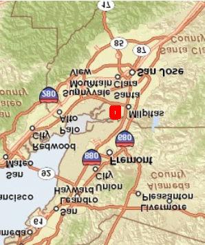
96 Pond A18 5 Pond A16 G:\028_167691_USACE_SF_Shoreline\map_docs\mxd\Scratch\BTJ\Utility_Maps\Fig2B_City_San_Jose_Database.mxd Last Updated : Artesian Slough Los Esteros Rd San Jose Santa Clara Water Treatment Plant 0 1,000 2,000 Feet 1 inch = 600 feet City of San Jose Utilities Database Figure 2B USACE SF Shoreline E1-94


97 Appendix E1 - Civil Design Pond A18 Pond A16 Don Edwards Center New Chicago Marsh ian t es Ar 1 Sl o 2 ug h G:\028_167691_USACE_SF_Shoreline\map_docs\mxd\Scratch\BTJ\Utility_Maps\Fig3_Aerial_Street_Level_Photos.mxd Last Updated : G 7 ra nd vd Bl Los Estro s R oad Alviso S lough 0 1,000 1 inch = 600 feet 2,000 Feet Aerial and Street Level Photos of Utilities Figure 3 USACE SF Shoreline E1-95
98 E1-96
99 Attachment I NED Planset E1-97
100 E1-98
101 US Army Corps of Engineers San Francisco District Santa Clara County California E1-99
102 E1-100
103 Appendix E1 - Civil Design E1-101
104 E1-102
105 E1-103
106 E1-104
107 E1-105
108 E1-106
109 E1-107
110 E1-108
111 E1-109
112 E1-110
113 E1-111
114 E1-112
115 E1-113
116 E1-114
117 E1-115
118 E1-116
119 E1-117
120 E1-118
121 E1-119
122 E1-120
123 E1-121
124 E1-122
125 E1-123
126 E1-124
127 E1-125
128 E1-126
129 E1-127
130 E1-128
131 E1-129
132 E1-130
133 E1-131
134 E1-132
135 E1-133
136 E1-134
137 E1-135
138 E1-136
139 E1-137
140 E1-138
141 E1-139
142 E1-140
143 E1-141
144 E1-142
145 E1-143
146 E1-144
147 E1-145
148 E1-146
149 E1-147
150 E1-148
151 E1-149
152 E1-150
153 E1-151
154 E1-152
155 E1-153
156 E1-154
157 E1-155
158 E1-156
159 E1-157
160 E1-158
161 E1-159
162 E1-160
163 E1-161
164 E1-162
165 E1-163
166 E1-164
167 Attachment II LPP Planset E1-165
168 E1-166
169 US Army Corps of Engineers San Francisco District Santa Clara County California E1-167
170 E1-168
171 E1-169
172 E1-170
173 E1-171
174 E1-172
175 E1-173
176 E1-174
177 E1-175
178 E1-176
179 E1-177
180 E1-178
181 E1-179
182 E1-180
183 E1-181
184 E1-182
185 E1-183
186 E1-184
187 E1-185
188 E1-186
189 E1-187
190 E1-188
191 E1-189
192 E1-190
193 E1-191
194 E1-192
195 E1-193
196 E1-194
197 E1-195
198 E1-196
199 E1-197
200 E1-198
201 E1-199
202 E1-200
203 E1-201
204 E1-202
205 E1-203
206 E1-204
207 E1-205
208 E1-206
209 E1-207
210 E1-208
211 E1-209
212 E1-210
213 E1-211
214 E1-212
215 E1-213
216 E1-214
217 E1-215
218 E1-216
219 E1-217
220 E1-218
221 E1-219
222 E1-220
223 E1-221
224 E1-222

225 E1-223