COMMUNAL WELL SYSTEM IN THE COMMUNITY OF LYNDEN
|
|
|
- Agatha Freeman
- 5 years ago
- Views:
Transcription
1 ENVIRONMENTAL STUDY REPORT COMMUNAL WELL SYSTEM IN THE COMMUNITY OF LYNDEN SCHEDULE C MUNICIPAL CLASS ENVIRONMENTAL ASSESSMENT MARCH 2017
2


3 COMMUNAL WELL SYSTEM IN THE COMMUNITY OF LYNDEN SCHEDULE C MUNICIPAL CLASS ENVIRONMENTAL ASSESSMENT Environmental Study Report Final Report Project No: Date: March 2017 PREPARED BY Michelle Albert, P.Eng, Project Manager WSP Canada Inc. WSP Canada Inc. 100 Commerce Valley Drive West Thornhill, Ontario L3T 0A1 T F
4
5 iii E X E C U T I V E S U M M A R Y The City of Hamilton ( the City ) has completed a Schedule C Municipal Class Environmental Assessment (EA) Study for the communal well system in the community of Lynden. The main objective of the Study is to identify, develop and implement a strategy to provide a secure water supply to this community. Lynden Rural Settlement Area (RSA) is a groundwater sourced municipal drinking water system, located approximately 13 km west of the City s urban area. The Lynden RSA is currently supplied from a single groundwater well (FDL01) and single storage/treatment facility located on Governor s Road, approximately 1.5 km east of Lynden Road. The main distribution system is concentrated on Lynden Road north of Governor s Road. In 2001, the Lynden RSA groundwater supply experienced a combination of high demand and turbidity levels which prompted the commencement of the Water Servicing Master Plan. Phases 1 and 2 of the Municipal Class Environmental Assessment (EA) process was undertaken in the 2002 Master Plan to address the following conditions in the existing Lynden potable water supply system: The communal water supply system is dependent on a single well and treatment system, which provides no redundancy to ensure a secure supply. The existing water supply system requires a capacity assessment to ensure it can meet the future demands of the water servicing area. A treatment system is required to reduce hydrogen sulphide and turbidity concentration in the treated water. Following a re-assessment of the 2002 Master Plan alternatives, it was found that there have been no significant changes in the system and the recommendation to Upgrade the Existing Well System is still the preferred alternative. Therefore, between 2008 and 2016, an extensive drilling program was undertaken to locate a new backup well to improve system redundancy. The groundwater exploration process led to the acquisition of property south of the FDL01 site and the drilling and testing of a new well (FDL03) which is able to pump at 6.0 L/s to meet the future demand. The groundwater quality sampling from FDL03 indicates that the well water meets the Ontario Drinking Water Standards objectives and guidelines for all parameters listed in Schedule 23 and 24 of O.Reg. 170/03, except for hydrogen sulphide and hardness. The recommended design alternative consists of construction of a new pumping station and reservoir to rectify current deficiencies. This solution is a key component of the City s long term plan to provide safe and secure drinking water to its residents. As part of this Class EA, the City considered several sites and alternative design concepts to confirm the preferred solution and implementation. Ideas, concepts, sites were evaluated based on set of criteria that considered technical viability, environmental impacts, socioeconomic impacts and financial costs. This Municipal Class EA Environmental Study Report (ESR) has been prepared to confirm that the proposed new backup well, pumping station and reservoir project meets the requirements of the EAA. Consideration of potential impacts and recommended mitigation measures was included as part of the evaluation of the preferred solution. Communal Well System in the Community of Lynden WSP Environmental Study Report No March 2017
6
7 v TABLE OF CONTENTS 1 INTRODUCTION AND BACKGROUND PURPOSE AND STUDY BACKGROUND RELATED POLICIES AND REGULATIONS THE PLANNING ACT, ONTARIO PLANNING AND DEVELOPMENT ACT, PLACES TO GROW ACT, PROVINCIAL POLICY STATEMENT, GROWTH PLAN FOR THE GREATER GOLDEN HORSESHOE, HAMILTON RURAL OFFICIAL PLAN, CLEAN WATER ACT, 2006, AMMENDED GREENBELT ACT, CITY OF HAMILTON BY-LAW NO. R RELATED STUDIES ENGINEER S REPORT FOR THE LYNDEN WELL SYSTEM (MACVIRO, 2001) COMPREHENSIVE WATER SERVICING MASTER PLAN FOR THE LYNDEN RURAL SETTLEMENT AREA (TSH, 2002) PRELIMINARY GUDI EVALUATION (STANTEC, 2004) HAMILTON GROUNDWATER RESOURCES CHARACTERIZATION AND WELLHEAD PROTECTION PARTNERSHIP STUDY (CHARLESWORTH & ASSOCIATES, SNC LAVALIN, 2006) IDENTIFICATION OF POTENTIAL LOCATIONS FOR A MUNICIPAL SUPPLY WELL FOR THE COMMUNITY OF LYNDEN (XCG CONSULTANTS, 2006) TECHNICAL MEMORANDUM, EVALUATION OF ALTERNATIVES FOR POTENTIAL WELL LOCATIONS (GENIVAR, 2007) GRAND RIVER ASSESSMENT REPORT (LAKE ERIE SOURCE PROTECTION COMMITTEE, 2015), AMMENDED TECHNICAL MEMORANDUM, SUMMARY OF HYDROGEOLOGICAL CONDITIONS IN THE LYNDEN AREA (GENIVAR, 2008) REPORT ON INSPECTION AND REPAIRS TO THE LYNDEN WATER TREATMENT FACILITY AERATION AND DISINFECTION RESERVOIR CELLS, (ASI GROUP, 2009) ONTARIO GEOLOGICAL SURVEY EXPLORATORY PROGRAM Communal Well System in the Community of Lynden WSP Environmental Study Report No March 2017
8 vi ESTIMATION OF WELL YIELD FOR PROPOSED MUNICIPAL WELL 3618 GOVERNORS ROAD, LYNDEN, ONTARIO (AMEC, 2011) INVESTIGATION OF LEAD DETECTIONS AT THE LYNDEN DRINKING WATER SYSTEM (XCG CONSULTANTS LTD., 2012) TESTING PROGRAM FOR LYNDEN SUPPLY WELL FDL02 (GENIVAR, 2013) TREATEMENT ALTERNATIVES TECHNICAL MEMORANDUM (WSP, 2013) LYNDEN BARIUM WELL ASSESSMENT (WSP, 2014) GRAND RIVER SOURCE PROTECTION PLAN (LAKE ERIE SOURCE PROTECTION COMMITTEE, 2016) TESTING PROGRAM REPORT FOR FDL03 (WSP, 2016) ENVIRONMENTAL ASSESSMENT ACT PRINCIPLES OF ENVIRONMENTAL PLANNING MUNICIPAL CLASS ENVIRONMENTAL ASSESSMENT LYNDEN COMMUNAL WELL SYSTEM CLASS EA CATEGORY PHASE 1: PROBLEM STATEMENT DEFINITION OF PROBLEM OR OPPORTUNITY DESCRIPTION OF THE EXISTING SYSTEM WELL FDL UNDEGROUND TWO-CELL RESERVOIR COMPRESSED AIR SYSTEM HIGH LIFT PUMPING STATION (HLPS) SECONDARY DISINFECTION AND TURBIDITY ANALYZER EXISTING CONDITIONS STUDY AREA NATURAL HERITAGE FEATURES ARCHAEOLOGICAL, BUILT & CULTURAL HERITAGE RESOURCES GEOLOGICAL AND HYDROGEOLOGICAL SITE CONDITIONS WATER SYSTEM CONSTRAINTS HISTORICAL WATER DEMAND PROJECTED WATER DEMAND (ULTIMATE BUILDOUT) WATER STORAGE REQUIREMENTS Communal Well System in the Community of Lynden WSP Environmental Study Report No March 2017
9 vii 4 PHASE 2: ALTERNATIVE SOLUTIONS PHASE 2A: IDENTIFICATION OF ALTERNATIVE SOLUTIONS ALTERNATIVE 1 DO NOTHING ALTERNATIVE 2 WATER CONSERVATION / DEMAND ALTERNATIVE 3 UPGRADE EXISTING WELL SYSTEM ALTERNATIVE 4 NEW GROUNDWATER SUPPLY ALTERNATIVE 5 CONNECT TO AN ADJACENT SYSTEM PHASE 2B: EVALUATION OF ALTERNATIVE SOLUTIONS PHASE 3: ALTERNATIVE DESIGNS GENERAL CONSTRUCTION OF BACKUP WELL LEAD CONCERNS DESIGN ALTERNATIVES DESIGN ALTERNATIVE 1 - EXPANSION OF THE EXISTING PUMPING STATION AND UTILIZING THE EXISTING RESERVOIR DESIGN ALTERNATIVE 2 - EXPANSION OF THE EXISTING PUMPING STATION AND NEW RESERVOIR DESIGN ALTERNATIVE 3 - NEW PUMPING STATION AND NEW RESERVOIR PHASE 3: EVALUATION OF ALTERNATIVES EVALUATION CRITERIA AND METHODOLOGY COMPARATIVE EVALUATION OF ALTERNATIVES PREFERRED ALTERNATIVE POTENTIAL EFFECTS AND MITIGATING MEASURES NATURAL ENVIRONMENT IMPACTS TERRESTRIAL VEGETATION WILDLIFE AND WILDLIFE HABITATS FISHERIES WETLAND INTERFERENCE WITH SURFACE AND SUBSURFACE FLOWS SOCIAL, CULTURAL AND ECONOMIC IMPACTS Communal Well System in the Community of Lynden WSP Environmental Study Report No March 2017
10 viii TRAFFIC ARCHAEOLOGICY AND HERITAGE FEATURES NOISE, DUST AND VIBRATION ODOUR AND CORROSION PUBLIC NOTIFICATION PUBLIC AND AGENCY CONSULTATION PUBLIC NOTICES NOTICE OF STUDY COMMENCEMENT PUBLIC INFORMATION CENTRE PUBLIC INFORMATION CENTRE NOTICE OF COMPLETION CONCLUSIONS AND RECOMMENDATIONS BIBLIOGRAPHY Communal Well System in the Community of Lynden WSP Environmental Study Report No March 2017
11 ix T A B L E S TABLE 3-1 DETAILS OF THE LYNDEN MUNICIPAL WATER SUPPLY PERMIT TO TAKE WATER TABLE 3-2 WATER DEMAND TABLE 3-3 TABLE 3-4 ULTIMATE BUILDOUT AVERAGE AND MAXIMUM DAY DEMANDS STORAGE REQUIREMENTS FOR ULTIMATE BUILD-OUT (UB) DEMANDS TABLE 4-1 EVALUATION OF ALTERNATIVE SOLUTIONS TABLE 5-1 DESIGN ALTERNATIVES TABLE 5-2 CAPACITY ANALYSIS FOR ALTERNATIVE TABLE 5-3 DESIGN ALTERNATIVE 1 - COST ESTIMATE TABLE 5-4 CAPACITY ANALYSIS FOR ALTERNATIVE TABLE 5-5 DESIGN ALTERNATIVE 2 - COST ESTIMATE TABLE 5-6 CAPACITY ANALYSIS FOR ALTERNATIVE TABLE 5-7 DESIGN ALTERNATIVE 3 - COST ESTIMATE TABLE 6-1 PHASE 3 EVALUATION OF ALTERNATIVES F I G U R E S FIGURE 1-1 LYNDEN RURAL SETTLEMENT AREA BOUNDARY... 1 FIGURE 1-2 POTENTIAL WELL LOCATIONS FOR LYNDEN SUPPLY WELL FIGURE 2-1 KEY FEATURES OF THE MUNICIPAL CLASS EA FIGURE 2-2 MUNICIPAL CLASS EA PROCESS FIGURE 3-1 LOCATION OF THE EXISTING PUMPING STATION AND STUDY AREA FIGURE 3-2 EXISTING PUMPING STATION AND WELL (FDL01) FIGURE 3-3 EXISTING PUMPING STATION PROCESS ROOM FIGURE 3-4 FIGURE 3-5 EXISTING PUMPING STATION ELECTRICAL AND BLOWERS ROOM EXISTING LYNDEN WELL SYSTEM PROCESS FLOW DIAGRAM (PFD) FIGURE 3-6 NATURAL HERITAGE STUDY AREA FIGURE 3-7 ZONE OF INFLUENCE AND THE EXISTING NATURAL HERITAGE OF INTEREST FIGURE 3-8 LYNDEN WATER SUPPLY SYSTEM ARCHAEOLOGICAL ASSESSMENT STUDY AREA FIGURE 3-9 AREAS WITH ARCHEOLOGICAL POTENTIAL Communal Well System in the Community of Lynden WSP Environmental Study Report No March 2017
12 x FIGURE 3-10 FIGURE 5-1 FIGURE 5-2 LYNDEN RSA CURRENT AND FUTURE SERVICE CONNECTIONS ALTERNATIVE 1 - EXPANSION OF THE EXISTING PUMPING STATION AND UTILIZING THE EXISTING RESERVOIR PFD ALTERNATIVE 2 - EXPANSION OF THE EXISTING PUMPING STATION AND NEW RESERVOIR PFD FIGURE 5-3 ALTERNATIVE 3 - NEW PUMPING STATION AND NEW RESERVOIR PFD FIGURE 6-1 ALTERNATIVE EVALUATION CRITERIA A P P E N D I C E S APPENDIX A DRINKING WATER WORK PERMIT & LICENSE APPENDIX B PERMIT TO TAKE WATER (PTTW) APPENDIX C HAMILTON RURAL OFFICAL PLAN LYNDEN SETTLEMENT AREA APPENDIX D PUBLIC AND AGENCIES COMMENTS APPENDIX E RELATED STUDIES APPENDIX F NATURAL SCIENCES REPORT AND STAGE 1 ARCHEOLOGICAL STUDY APPENDIX G MTSC CRITERIA FOR EVALUATING POTENTIAL FOR BUILT HERITAGE RESOURCES AND CULTURAL HERITAGE LANDSCAPES CHECKLIST Communal Well System in the Community of Lynden WSP Environmental Study Report No March 2017
13 xi T A B L E O F A C R O N Y M S ACRONYM DOC EA ESR FCR GUDI HLP HRPO MAC MEA MOECC PFD PIC PPTW PPS RSA SCADA TDH UB ODWA ODWS WHPA WWIS ZOI DESCRIPTION Dissolved Organic Carbon Municipal Class Environmental Assessment Environmental Study Report Free Chlorine Residual Groundwater Under the Direct Influence of Surface Water High Lift Pump Hamilton Rural Official Plan Maximum Acceptable Concentration Municipal Engineers Association Ministry of Environment and Climate Change Process Flow Diagram Public Information Centre Permit to Take Water Provincial Policy Statement Lynden Rural Settlement Area Supervisory Control and Data Acquisition Total Dynamic Head Ultimate Build-Out Ontario Drinking Water Objectives Ontario Drinking Water Standards Wellhead Protection Areas Water Well Information System Zone of Impact Communal Well System in the Community of Lynden WSP Environmental Study Report No March 2017
14
, located approximately 13 km west of the")
15 1 1 INTRODUCTION AND BACKGROUND 1.1 PURPOSE AND STUDY BACKGROUND The City of Hamilton operates a groundwater sourced municipal drinking water system in the Lynden Rural Settlement Area (RSA), located approximately 13 km west of the City s urban area. The Lynden RSA is currently supplied from a single groundwater well (FDL01) and single storage/treatment facility located on Governor s Road, approximately 1.5 km east of Lynden Road. The main distribution system is concentrated on Lynden Road north of Governor s Road. Figure 1-1 shows the location of the communal well system and current Lynden RSA boundary. Figure 1-1 Lynden Rural Settlement Area Boundary In the fall of 2001, the groundwater supply experienced a combination of higher demand (the City received several requests by Lynden residents for additional connections to the municipal system over concerns associated with private service water quality and quantity) and high turbidity levels in the treated water, which prompted the commencement of a Water Servicing Master Plan in The Master Plan investigated the following alternatives to ensure the supply of water to the Lynden Community: 1. Do Nothing 2. Water Conservation 3. Upgrade Existing Well Supply 4. New Groundwater Supply 5. Connection to an Adjacent Water Distribution System Communal Well System in the Community of Lynden WSP Environmental Study Report No March 2017
16 2 The 2002 Master Plan concluded that the preferred option was to upgrade the existing pumping station that services the existing well and to improve the reliability of the water supply by establishing a back-up well while providing treatment to reduce the treated water turbidity. As the result, a Municipal Class Environmental Assessment (EA) was initiated in 2007 to address the following issues related to the existing Lynden potable water supply system: The communal water supply system is dependent on a single well and treatment system, which provides no redundancy to ensure a secure supply. The existing water supply system requires an assessment to evaluate its capacity to meet the future demands of the water servicing area. A treatment system is required to reduce hydrogen sulphide and turbidity concentration in the treated water. 1.2 RELATED POLICIES AND REGULATIONS THE PLANNING ACT, 1990 The Planning Act establishes the mechanisms and rules for land use planning in Ontario, outlining how land uses may be controlled, and who may control them. The Act sets the basis for the preparation of official plans and planning policies for future development, and it provides municipalities with local autonomy to make decisions and streamline the planning process. The Act empowers local citizens to provide their input to their municipal council and, where permitted, to appeal decisions to the Ontario Municipal Board. Through the Act, the Province issues Provincial Policy Statements and plans (e.g. Growth Plan for the Greater Golden Horseshoe, 2006) ONTARIO PLANNING AND DEVELOPMENT ACT, 1994 The Ontario Planning and Development Act, 1994 establishes the general approach by which the Minister of Municipal Affairs and Housing may require for Development Plans to be undertaken for development planning areas. The Development Plans may include policies for economic, social and physical development with relation to the distribution and density of population within the development area, the location of employment areas, the identification of land use areas, the management of land and water resources, the control of all forms of pollution of the natural environment, the location and development of servicing, communication and transportation systems and the development and maintenance of educational, cultural, recreational, health and other social facilities. There also may be policies relating to the financing and programming of public development projects and capital works, and policies to coordinate planning and development among municipalities or planning boards within an area or within separate areas, among other considerations PLACES TO GROW ACT, 2005 The Places to Grow Act (2005) provides a framework for the Provincial government to coordinate planning and decision-making for long-term growth and infrastructure renewal in Ontario. It gives the Province the authority to designate geographical growth areas, and to develop growth plans in collaboration with local officials and stakeholders to meet specific needs across the Province. Growth plans developed under the Places to Grow Act integrate and build upon other initiatives such as the Greenbelt Plan, the Niagara Escarpment Plan, the Provincial Policy Statement, the Planning Act, municipal infrastructure planning, and source water protection planning. Growth plans may include population projections and allocations, policies, goals and criteria relating to issues such as intensification and density, land supply, expansions and Communal Well System in the Community of Lynden WSP Environmental Study Report No March 2017
17 3 amendments to urban boundaries, location of industry and commerce, protection of sensitive and significant lands (including agricultural lands and water resources), infrastructure development, affordable housing and community design. Municipalities are required to bring their official plans into conformity with the growth plan for their area. Decisions made under the Planning Act and Condominium Act is also required to conform to applicable growth plans PROVINCIAL POLICY STATEMENT, 2014 The Provincial Policy Statement (PPS), 2014 is a key component of Ontario s planning system as it sets policy direction on matters of provincial interest related to land use planning, growth management, environmental protection, and public health and safety. It aims to provide a stronger policy framework that guides communities in Ontario toward a higher quality of life and a better long-term future. The PPS establishes the City s role in planning for growth, intensification and redevelopment. The PPS identifies that development within designated areas must proceed based on the extension of municipal water supply and wastewater collection systems. New settlement area policies will only permit expansions where it is demonstrated that opportunities for growth are not available through intensification, redevelopment or in previously designated areas. The PPS also requires municipalities to co-ordinate and provide direction on policies with cross municipal boundaries, such as natural heritage systems and resource management. It also provides the context for the City s participation in the Growth Plan for the Greater Golden Horseshoe GROWTH PLAN FOR THE GREATER GOLDEN HORSESHOE, 2006 The City of Hamilton is part of the Greater Golden Horseshoe, for which The Growth Plan was prepared and approved under the Places to Grow Act, The Growth Plan for the Greater Golden Horseshoe contains a framework for implementing the Government of Ontario s vision for building stronger, prosperous communities by better managing growth to The Plan has been built upon other government initiatives including: the Planning Act reform and the Provincial Policy Statement, Though the Plan is not meant to replace municipal official plans, it works within the existing planning framework to provide growth management policy direction for the Greater Golden Horseshoe. Specifically, the Plan establishes growth forecasts, intensification policies and targets, and development density targets for urban and Greenfield areas. It also provides guidance on issues such as transportation, infrastructure planning, land-use planning, urban form, housing, natural heritage and resource protection with the goal of promoting economic prosperity to areas within the Greater Golden Horseshoe HAMILTON RURAL OFFICIAL PLAN, 2014 The new Official Plans for the amalgamated City of Hamilton have been separated into two policy documents: Rural and Urban. The Hamilton Official Plans identify the locations of the existing and future land uses such as parks and open space, residential, commercial, institutional and industrial uses. These plans also distinguish between the urban and rural areas, as well as identify the natural and environmentally significant areas. The Hamilton Rural Official Plan (HROP) was adopted by Council in 2006 and came into effect in 2012, followed by an amendment in Communal Well System in the Community of Lynden WSP Environmental Study Report No March 2017
18 4 The HROP is a document including policy that provides guidance based on a broad perspective and deals with rural concerns such as protection of natural resources. The HRPO identifies the rural development pattern as well as the infrastructure provisions. The policies of this plan provide a framework that integrates the concepts from the Regional Plan, Federal and Provincial Legislation, and local objectives, so as to guide and direct growth in an orderly and efficient manner. The study area for this project lies within the Flamborough Rural Settlement Area. Please refer to Rural Hamilton Official Plan Volume 2 for further details on Lynden Rural Settlement Area CLEAN WATER ACT, 2006, AMMENDED 2012 The purpose of the Clean Water Act, 2006, is to protect existing and future sources of drinking water and part of the Ontario government s commitment to ensure that all Ontarians have access to safe drinking water. The Clean Water Act requires municipalities to create and carry out a plan based on sound science to protect the sources of their drinking water supply by looking at potential threats to their water supply and opportunities to mitigate or eliminate these threats. The Act also requires public participation on all local source protection plans GREENBELT ACT, 2005 The Greenbelt Act, 2005, and the associated Greenbelt Plan identified an area around the Golden Horseshoe and designated it the Greenbelt. The Greenbelt Act ensures the permanent protection of the agricultural land base and the ecological features and functions occurring on this Greenbelt. Lynden is located within the Greenbelt, therefore is subject to the policies included with the Act. In order to limit development in the Greenbelt and protect the Greenbelt from urban sprawl, the policy outlined in Section of the Greenbelt Plan prohibits the connection of settlements within the Greenbelt to a Great Lake based water system. Where settlements do not currently have Great Lake or Lake Simcoe based water and sewage services, extensions to or expansions of existing Great Lake or Lake Simcoe based services to such settlements is not permitted, unless such servicing is required to address failed individual on-site sewage or water services or to ensure the protection of public health where it has been determined by a medical officer of health (or health authority) that there is a public health concern associated with existing services within the settlement. The capacity of the services provided in these circumstances will be restricted to that required to service the affected existing settlement plus the capacity for potential development within the approved settlement boundary as it existed on the date this Plan came into effect. Reference: The City of Hamilton currently obtains its drinking water from the Lake Ontario which his part of Great Lakes. Therefore, the extension of the urban water distribution to the Lynden RSA is not permitted at this time CITY OF HAMILTON BY-LAW NO. R This By-Law consolidates the contents of certain Regional By-Laws respecting water management, distribution, and maintenance of water systems in the Regional area, and respecting the establishment of water rates and charges. The new well and associated facility will provide the system with redundancy to Communal Well System in the Community of Lynden WSP Environmental Study Report No March 2017
19 5 ensure a secure supply and will meet the needs of the potential ultimate water servicing areas, which would include all properties able to petition for connection based on the City of Hamilton By-Law No. R RELATED STUDIES ENGINEER S REPORT FOR THE LYNDEN WELL SYSTEM (MACVIRO, 2001) In August 2000, the Government of Ontario announced a new drinking water protection regulation (O. Reg. 459/00) to ensure the safety of Ontario s drinking water. Based on the first new Drinking Water Protection Regulation, municipalities were required to submit the Engineers Reports for their water works to the Director of the Ministry of the Environment and Climate Change (MOECC) between November 2000 and May 2001 as specified in the MOE publication entitled Drinking Water Submission Dates for First Engineers Report. MacViro was retained by the City of Hamilton to prepare the Engineer s Report for the Lynden Well System. The City of Hamilton made available for the purpose of this report the microbiological reports for the following years: 1998, 1999 and In all years with the exception of 1999, the monitoring program met and exceeded the Ontario Drinking Water Objectives (ODWO) requirements for the number of microbiological samples and there were zero (0) occurrences of E.Coli in the finished water. In 1999, the monitoring program fell just short of the ODWO requirements for the number of microbiological samples. The key raw water quality parameters for the Lynden Well System includes turbidity, organic material (as quantified by dissolved organic carbon DOC), temperature, ph, colour, alkalinity, nitrate, sodium, iron, manganese, total hardness and sulphides. Provided below are the raw water characteristics: Turbidity recorded in raw water is very low ranging from 0.01 to 0.05 NTU. The Ontario Drinking Water Standards set a Maximum Acceptable Concentration (MAC) for turbidity of 1.0 NTU in drinking water leaving the treatment plant to ensure the efficiency of the disinfection process. In reviewing the test results of some 100 turbidity samples for the raw and treated water at Well FDL01, i.e. Station ID L-5A and L-5AAC used by the City of Hamilton s Environmental Laboratory, over a 24-month period between October 1997 and September 2000, it is noted that the turbidity level for the treated water is generally higher than that of the raw water. There were 35 samples that exceeded 1.0 NTU with the highest 6.22 NTU recorded on October 26, The sodium in the Lynden well water samples ranged between 52.3 mg/l and mg/l. The Ontario Drinking Water Standards set an Aesthetic Objective for sodium at 200 mg/l. The Ontario Drinking Water Standards (ODWS) does not set a Standard or Objective for sulphides. This parameter will contribute to the taste and odour in the finished water. In December 2000, three (3) samples were tested for sulphides with the results ranging between 1.5 to 1.9 mg/l. The purpose of the Engineer s Report was to review the Lynden Well System and make recommendations for improvements that should be implemented to comply with the new Ontario Drinking Water Standards. Accordingly, the following summarizes the recommendations made throughout the report: 1. It is recommended that a study be performed to establish levels of DOC in the raw water. 2. It is recommended that the operation and maintenance manual should be updated as outlined below. Communal Well System in the Community of Lynden WSP Environmental Study Report No March 2017
20 6 3. It is recommended that the City investigate treatment options that reduce the sulphide levels in the groundwater without impacting negatively on the turbidity levels. The current treatment process increases the turbidity in the finished water to the degree that exceedances of ODWS have been reported. 4. It is recommended that the City implement a treatment process to reduce the DOC levels if the above mentioned study (item 1) confirms that levels of DOC are above the MAC in ODWS COMPREHENSIVE WATER SERVICING MASTER PLAN FOR THE LYNDEN RURAL SETTLEMENT AREA (TSH, 2002) The Comprehensive Water Servicing Master Plan for the Lynden Rural Settlement Area by Totten Sims Hubicki Associates was completed in August The 2002 Master Plan considered the existing water servicing area and the current water demand at that time for possible future connections and considered two development conditions: 1. Up to the capacity of the well pump house and permit to take water (327 m 3 /day or an estimated 154 connections) 2. Up to the capacity of the aquifer (estimated as 560 m 3 /day or 260 connections) The 2002 Master Plan considered the following alternatives for the Water Supply and Water Distribution System for the existing Lynden communal water system. Do Nothing Water Conservation Upgrade Existing Well Supply New Groundwater Supply Connection to an Adjacent Water Distribution System In addition to water supply alternatives, upgrades to the water distribution system were also reviewed under this Master Plan. The water distribution system upgrades were considered in conjunction with the preferred water supply alternatives. The water distribution system alternatives for the Lynden RSA included: Do Nothing Upgrade to Improve Operation Upgrade for Fire Protection System Storage for Pressure Control Based on the community input, technical, environmental and economic criteria, it was recommended that the City of Hamilton upgrade the existing well to include treatment to reduce the treated water turbidity, and the addition of a backup well. It was recommended to implement this alternative for the water supply immediately. Additionally, it was recommended that the City of Hamilton proceed with looping the system to improve operations. Looping the system would improve the efficiency of operations, including the distribution of chlorine and maintain higher pressures at system endpoints, allowing for expansion at either the north or south end of Lynden Road. The recommended looping included the installation of water mains to eliminate dead end water mains as well as the installation of valves to allow smaller sections of the waterman to be Communal Well System in the Community of Lynden WSP Environmental Study Report No March 2017
21 7 isolated in the event of repairs, ensuring continuity of supply to the residents. It was recommended to implement this alternative for the water distribution system immediately. Once the additional connections to the water system were accounted for, the Master Plan recommended that the City of Hamilton undertake a hydrogeological investigation to verify if the aquifer can be pumped to its capacity (560 m 3 /d) without adverse effects to the local private wells. To summarize the recommendations of the Master Plan, the preferred servicing solution included the following items: Upgrades to the existing well (FDL01). Install water mains to provide looping in the distribution system. Develop well head protection strategy. Undertake a hydrogeological study to determine aquifer capacity and well interference. and, Construct a second source well PRELIMINARY GUDI EVALUATION (STANTEC, 2004) The Preliminary GUDI Evaluation, Lynden Municipal Well FDL01 by Stantec was completed in February The City of Hamilton (City) retained Stantec Consulting Inc. (Stantec) to complete a desktop review to determine the status of the groundwater of Municipal Well FDL01 (FDL01) under the Safe Drinking Water Act (2002) and to provide recommendations for additional work, if required. O. Reg. 170/03 Section 2(2) provides seven criteria to determine if a water supply system is considered to be potentially Groundwater Under the Direct Influence of Surface Water (GUDI). Criteria 1, 4 and 6 were identified as applicable to FDL01: 1 - A drinking-water system that obtains water from a well that is not a drilled well or from a well that does not have a watertight casing that extends to a depth of six metres below ground level. 4 - A drinking-water system that is capable of supplying water at a rate greater than 0.58 L/s and that obtains water from an overburden well, any part of which is within 100 metres of surface water. 6 - A drinking-water system that exhibits evidence of contamination by surface water. Based on the results of the desktop review, FDL01 was not considered GUDI for the following reasons: The casing is intact and water tight. The overburden aquifer screened by FDL01 is confined by a thick clay and silt aquitard. Based on the depth to the water table and the composition of the overlying material, the susceptibility of the aquifer to contamination from surface was estimated to be low. The pumping test in 1987 did not indicate any drawdown in the shallow aquifer. The nearest surface water feature is 250m away. The raw water does not show any evidence of surface water contamination. Communal Well System in the Community of Lynden WSP Environmental Study Report No March 2017
22 HAMILTON GROUNDWATER RESOURCES CHARACTERIZATION AND WELLHEAD PROTECTION PARTNERSHIP STUDY (CHARLESWORTH & ASSOCIATES, SNC LAVALIN, 2006) A groundwater resource characterization and wellhead protection study was undertaken by Charlesworth and Associates and SNC Lavalin (2006) for the City of Hamilton. The study covered the entire amalgamated City of Hamilton area that was dependent on groundwater supplies. As part of this work, the following major tasks were accomplished: Regional groundwater resources characterization Aquifer vulnerability assessment Regional contaminant sources inventory Groundwater use assessment Wellhead protection areas (WHPA) delineation for municipal wells WHPA contaminant sources inventory Policy planning and education In accordance with the MOECC terms of reference for hydrogeological investigations, a number of maps were created at a regional scale that were to be used as a starting point for any future studies. It was recommended that more detailed studies be undertaken to confirm information for local scale investigations. A total of twenty-three (23) recommendations were made in this report. Most of these were very general, but the recommendation of the greatest concern to Lynden area residents related to the potential restriction of land uses within the wellhead protection area of the municipal well and proposed backup well IDENTIFICATION OF POTENTIAL LOCATIONS FOR A MUNICIPAL SUPPLY WELL FOR THE COMMUNITY OF LYNDEN (XCG CONSULTANTS, 2006) A desktop hydrogeological study was conducted by XCG Consultants Inc. (2006) to identify a suitable location for a municipal supply well. As part of the study the following topics were reviewed: Hydrogeology of the area Water quality in existing wells Susceptibility of the target aquifer to contamination Potential sources of contamination Land use Potential for interference with private well users This information was used to develop a set of screening criteria to choose an appropriate site for a new well. Sites were rated based on the following ten criteria: Probability of the new well being capable of supplying >5 L/sec Proximity to Lynden Proximity to distribution system Communal Well System in the Community of Lynden WSP Environmental Study Report No March 2017
23 9 City owned land Potential for GUDI classification Predicted Intrinsic susceptibility index Well interference potential Physical constraints Potential impacts on surface water bodies Water quality Based on the results of the review of available geological, hydrogeological, and geochemical data, it was recommended that any new well be screened in the deep gravel aquifer as there is a higher probability that this aquifer could supply the desired 5 L/sec. Five (5) possible sites were identified for the new well: Site A - South side of Governor's Road, approximately 200 metres west of well FDL01 Site B - South side of Governor's Road, approximately 100 metres east of well FDL01 Site C - South side of Governor's Road, approximately 800 metres east of well FDL01 Site D - Along east side of Lynden Road, approximately 750 metres north of Governor's Road Site E - South side of Governor's Road, approximately 750 metres west of well FDL01 Based on the evaluation of each site against the defined criteria, Site E was ranked slightly higher than Site A due to the latter s proximity to the existing supply well. Having wells separated by a greater distance is prudent in the event that aquifer contamination occurs TECHNICAL MEMORANDUM, EVALUATION OF ALTERNATIVES FOR POTENTIAL WELL LOCATIONS (GENIVAR, 2007) In 2007, following the XCG desktop assessment for potential well locations, an additional alternative was identified for inclusion in the selection process for siting of the new backup well. The new location (Site F) was identified as being City owned property on the north side of Governor s road approximately 500 m east of existing well FDL01 (Figure 1-2). Communal Well System in the Community of Lynden WSP Environmental Study Report No March 2017
24 10 Figure 1-2 Potential Well Locations for Lynden Supply Well The site was evaluated using the same criteria presented by XCG (2006) and designated as Alternative F. The alternative compared favourably with the others, with the exception of distance to the distribution system and distance to Lynden. However, the location had the strategic advantage of being on land owned by the City of Hamilton. This advantage would allow test well construction immediately without having to undergo the potentially time consuming and expensive process of procuring additional property GRAND RIVER ASSESSMENT REPORT (LAKE ERIE SOURCE PROTECTION COMMITTEE, 2015), AMMENDED 2017 The Grand River Assessment Report, 2015 is the scientific base for the Grand River Source Protection Plan, as required in the Clean Water Act (2006). The Assessment Report provides an introduction to the Source Protection Planning process and the roles and responsibilities of the Lake Erie Region Source Protection Committee, Municipalities and conservation authorities. The Report delineates all vulnerable areas within the Grand River Area and summarizes the threats and issues of evaluation in each vulnerable area. The Grand River watershed area contains 49 municipal drinking water systems and one system that services a First Nations Reserve. The City of Hamilton is included within this area and operates one groundwater system in the watershed. This system is known as the Lynden Communal Well System FDL01. The report had the following findings: There is no evidence of a Condition for the Lynden Communal Well Supply, no data is available. Communal Well System in the Community of Lynden WSP Environmental Study Report No March 2017
25 11 A total 20 significant threats, involving 7 land parcels were identified. These threats are preliminary associated with agricultural activities in the area and the use of septic systems and potential heating fuel tanks associated with residential dwellings. Wellhead Protection Areas were delineated using a combination of most up to date field data and desktop methods, including: Capture zones and time of travel zone analysis using the USGS MODPATH code Mapping the aquifer vulnerability and development of vulnerability using Surface to Aquifer Advective Time (SAAT) approach outside of the wellhead protection areas TECHNICAL MEMORANDUM, SUMMARY OF HYDROGEOLOGICAL CONDITIONS IN THE LYNDEN AREA (GENIVAR, 2008) After comments were received at the first Public Information Centre (PIC no.1), GENIVAR carried out a detailed review of available hydrogeological reports to assess the regional and local hydrogeology of the Lynden area in the process to identify suitable locations for development of additional groundwater sources. The review considered the following: Geology and Hydrogeology of the Lynden Area Existing Lynden Well Potential areas for backup supply Studies conducted over the previous 30 years have provided a clear understanding of the hydrogeological conditions in the Lynden Area. The studies identified a deep confined gravel aquifer to the east of Lynden protected from surficial processes by a thick layer of clay and silt. In general, the shallow aquifer and bedrock aquifer are not suitable for municipal supply due to water quality and quantity concerns. The report recommended that the drilling of a new well should proceed at the recommended location with a second preferred location identified as a possible backup. Also, communication with local residents should be the highest priority based on previous and current opposition to drilling in the Lynden area REPORT ON INSPECTION AND REPAIRS TO THE LYNDEN WATER TREATMENT FACILITY AERATION AND DISINFECTION RESERVOIR CELLS, (ASI GROUP, 2009) In 2008, a sudden increase in turbidity and lead concentration was observed in Lynden drinking water system. ASI Group Ltd. (ASI) was retained by the City in 2009 to conduct a detailed inspection, infrastructure assessment and survey of the Lynden treatment facility. The specific works performed are listed below: Dewater, enter and inspect the reservoir cell(s). Remove the aging baffle curtains and hardware. Inspect all hardware for wear and replace as necessary. Provide and install new baffle curtains, consistent with the original design. Wash/clean the reservoir cells and remove all debris and residual water for disposal at a municipal wastewater treatment plant (WWTP, Dundas and/or Woodward Ave.). Communal Well System in the Community of Lynden WSP Environmental Study Report No March 2017
26 12 Survey and assess the condition of the infrastructure in each cell, including the concrete, seals, hardware, piping, aerator header pipes and nozzles, valves, pumps, chlorine solution line piping, etc. Disinfect the reservoir cell following cleaning and installation of new baffle curtains. The report recommended exercising the valves in the reservoir cells at least once every six months to prevent future valve seizing. Also ASI recommended that the City increase the frequency of inspection of the disinfection cell while closely monitoring the condition of the aeration cell. ASI concluded the high turbidity/lead event in 2008 was due to the agitation caused by the aeration in the disinfection cell and resuspension of the settled solids. Therefore, a more stringent cleaning schedule was recommended to avoid accumulation of the solids in the disinfection cell and their entrance to the distribution system which could result in possible contamination. All the baffle curtains were recommended to be replaced every ten to fifteen years ONTARIO GEOLOGICAL SURVEY EXPLORATORY PROGRAM In 2008, the province approached the City with funds to undertake deep well explorations in the buried Dundas Valley. This funding opportunity was an excellent opportunity to test for a preferred municipal well site while fulfilling the grant agreement requirements for the Province's Ontario Geological Survey. Between 2008 and 2010, around ten exploratory wells were drilled to the South, North West, North and East of the existing supply well. However none of the exploration wells served to provide an adequate supply for either quality or quantity ESTIMATION OF WELL YIELD FOR PROPOSED MUNICIPAL WELL 3618 GOVERNORS ROAD, LYNDEN, ONTARIO (AMEC, 2011) After two years of exploration around the community of Lynden, the City of Hamilton purchased the property at 3618 Governors Road (behind FDL01). Three exploratory boreholes were drilled under the direction of the City to locate a suitable site for a potential backup supply well. One of these boreholes was chosen as a location for further investigation. AMEC was retained to assess the potential of the local deep aquifer to provide a backup supply of potable water. As such, a temporary 6-inch diameter test well was drilled, and a variable rate hydraulic test (step test) was conducted at rates of 2 L/s and 3.2 to 3.4 L/s to assess capacity of the deep aquifer. Water quality sampling was conducted during the testing to evaluate water quality. Testing results suggested that the aquifer could sustain the required pumping rates and water quality showed exceedances of the Ontario Drinking Water Quality Standards for Barium and Hydrogen Sulphide. Once the step testing of the temporary 6-inch well was complete, the casing was pulled, the borehole was overdrilled and an 8-inch production well was installed and developed to a sand free condition. A constant rate test was conducted at 6.6 L/s for two hours and a drawdown of 1.6 m was measured. Based on these results, a longer constant rate test was recommended, along with additional water quality analysis INVESTIGATION OF LEAD DETECTIONS AT THE LYNDEN DRINKING WATER SYSTEM (XCG CONSULTANTS LTD., 2012) XCG Consultants Ltd. (XCG) was retained by the City to undertake a study to investigate the source of intermittent Lead exceedances in the Lynden drinking water system. The study indicates the raw water Lead concentration between 2006 and 2011 was consistently below the ODWS Maximum Acceptable Concentration (MAC) of 0.01 mg/l. However, Lead exceedances were observed during 2008, 2009 and 2011 for both treated water and distributed water with higher values in the distribution system. Based on limited data, the study suggested that elevated Lead levels correspond to elevated concentrations of Communal Well System in the Community of Lynden WSP Environmental Study Report No March 2017
27 13 copper, iron and zinc indicating that the source of metals in the treated water may be due to corrosion of the Lead containing equipment. The treated water Langelier Saturation Index (LSI) ranged from to +0.02, with average LSI of -0.14, indicating a slightly corrosive water. Some of the recommendations were summarized below: Replacing the well pump, booster pumps, fittings, and valves containing brass and/or bronze with equivalent stainless steel components in the water supply system during upgrades. During high turbidity incidents, water is to be sampled from both cells (aeration and contact chamber) in addition to raw and treated water samples. All samples to be analyzed using unfiltered and filtered samples and submitted to an accredited laboratory and analyzed for a full water quality scan. The suggested parameters for analysis include, but are not limited to turbidity, ph, alkalinity, hardness, sulphate, suphide, and metals. Condition assessment of the existing well pump, including examination of the impeller and any components containing brass or bronze for evidence of corrosion. Regular cleaning of cells to reduce the potential for any settled precipitates to be disturbed and introduced into the treated water TESTING PROGRAM FOR LYNDEN SUPPLY WELL FDL02 (GENIVAR, 2013) This report summarized the testing program for the 8-inch production well FDL02, which included: Private Water Well Survey and Implementation of Monitoring Program Step Drawdown Test 72-hour Constant Rate Aquifer Test Regulation 170/03 Chemical Analysis GUDI evaluation A private water well survey was conducted for all residents within 500 m of the proposed well. This included the completion of a questionnaire, baseline water quality sampling, and requests to participate in a monitoring program. The monitoring included installation of data loggers in residential wells and occasional manual measurement of water levels. A step drawdown test indicated that FDL02 would sustain the target pumping rate of 4.7 L/s. A 72-hour constant rate test was carried out at 4.7 L/s to assess the capacity of the well. Well FDL01 was shut down during this test to allow for interpretation of data without significant interference. The maximum drawdown after 72 hours was measured to be 2.37 m. During the test, the groundwater was sampled at four intervals (i.e. after 1 hour, 24 hours, 48 hours and 72 hours of pumping) and sent for chemical analysis to assess groundwater quality with respect to the requirements of Regulation 170/03. Groundwater sampling indicated ODWS exceedances for Barium and Hydrogen Sulphide. A preliminary evaluation of the well indicated that FDL02 is likely not under the influence of surface water (GUDI). No well complaints were received during the test. The results of the testing showed that FDL02 can be operated as a backup to FDL01 at a maximum rate of 4.7 L/s. However, the well water will need to be treated for hydrogen sulphide and Barium prior to being connected to the local supply. Communal Well System in the Community of Lynden WSP Environmental Study Report No March 2017
28 TREATEMENT ALTERNATIVES TECHNICAL MEMORANDUM (WSP, 2013) In 2013 WSP completed a technical memorandum detailing the alternative treatment options for the new well FDL02. Also discussed in the memorandum was the raw water quality of the new well. After testing, it was determined that the groundwater quality from the new well met Ontario Drinking Water Standards, Objectives, and Guidelines for all parameters except for barium, sulfides, and hardness. Four treatment alternatives were identified which included the removal of both barium and sulfide. The alternatives presented were: Alternative 1: Ion Exchange/Oxidation/Filtration/Disinfection Alternative 2: Air Stripping/Ion Exchange/Disinfection Alternative 3: Air Stripping/Reverse Osmosis/Disinfection Alternative 4: Air Stripping/Lime Softening/Disinfection After analysis through an evaluation matrix based on economic, environmental, technical, and social criteria it was determined that the preferred treatment alternative was Alternative 1: Ion Exchange/Oxidation/ Filtration/Disinfection. This treatment process has the benefit of being able to treat the groundwater from both the original well (FDL01) and well FDL02, which would optimize flexibility if desired by the City LYNDEN BARIUM WELL ASSESSMENT (WSP, 2014) Because of the expense related to treating Barium in the groundwater, additional well exploration was conducted at 3618 Governors Road to try to identify a location where a new well could be drilled with lower Barium concentrations. Two 6-inch test wells were drilled into the target aquifer, one located approximately midway between FDL01 and FDL02, and the second located approximately 125 m south of FDL02. Water quality and soil sampling was conducted at both locations, and a step test was conducted on each well to assess aquifer capacity. The results of the program indicated that both locations could sustain the required pumping rates for a production well. However, the well closest to FDL01 and FDL02 had Barium levels of approximately 1.8 mg/l in the groundwater, which is above the ODWS criteria. The concentration of Barium in the southern well was 0.14 mg/l which is below the ODWS criteria. Greater quantities of Barium (as barite) were identified in the soil of the northernmost well (between FDL01 and FDL02). Therefore, the southernmost site was identified as the preferred location for drilling of a new production well GRAND RIVER SOURCE PROTECTION PLAN (LAKE ERIE SOURCE PROTECTION COMMITTEE, 2016) The Grand River Source Protection Plan sets out policies to protect sources of municipal drinking water such as the Lynden Municipal Well. These policies address existing and future drinking water threats related to: The conveyance of oil by way of underground pipelines Establishment, operation or maintenance of a waste disposal site Establishment, operation or maintenance of systems that collects, stores, transmits, treats or disposes of sewage The application and storage of agricultural source material Communal Well System in the Community of Lynden WSP Environmental Study Report No March 2017
29 15 The application, handling and storage of non-agricultural source material (NASM), fertilizer and pesticides The handling and storage of road salt Storage of snow The handling and storage of a dense non-aqueous phase liquid (DNAPL) The use of land as livestock grazing or pasturing land To achieve the objectives of the Source Protection Plan, the Clean Water Act, 2006 enables a range of approaches or policy tools such as: prohibiting the activity, requiring a Risk Management Plan for the activity, regulating land uses, using the existing provincial licencing process. In addition to the tools listed above, the Grand River Source Protection Plan prescribes development of education and outreach programs, incentive programs and establishment of stewardship programs. These policy approaches may be applied alone or in combination with other policy approaches to deal with a particular drinking water threat. In addition the implementation of the source protection policies requires the cooperation of the various partners such as the Lake Erie Source Protection Committee, Grand River Source Protection Authority, Province, municipalities and landowners. City of Hamilton is responsible for the delivery of municipal drinking water, land use planning and establishment of the Risk Management Office TESTING PROGRAM REPORT FOR FDL03 (WSP, 2016) WSP was retained by the City to procure a driller and oversee the drilling and testing of a new 8-inch diameter production well (FDL03) to act as the backup supply well for Lynden. The process involved the following tasks: Private Water Well Survey and Implementation of Monitoring Program Drilling, soil sampling and well construction Step drawdown test 72-hour Constant Rate Aquifer Test Regulation 170/03 Chemical Analysis GUDI evaluation A private water well survey was conducted for the residences within 500 m, and for those that participated in the monitoring program during the testing of FDL02. This included review of a questionnaire, collection of additional water quality samples, and confirmation of participation in a well monitoring program during the pumping test. A pilot hole was drilled and sampled, with grain size analysis and geophysical assessment of the aquifer completed in order to design the well screen. The well was developed to a sand free condition and a stepdrawdown test was performed to assess capacity. A 72-hour constant rate test was conducted at a rate of 6 L/s with a total drawdown of 2.81 m. Water quality samples were taken every 12 hours during the test, including a full suite of samples tested against the ODWS Tables 1-4. FDL01 was not shut down during this test, but there were no well complaints from nearby residents. The results of the test indicated that the well can sustain a rate of 6 L/s. Water quality results indicated aesthetic and operational guideline exceedances for hydrogen sulphide and hardness (naturally soft water). Barium and Lead levels were both measured to be well below the maximum acceptable concentrations (MAC) under the ODWS guidelines. A preliminary evaluation of the well indicated that FDL03 is not under Communal Well System in the Community of Lynden WSP Environmental Study Report No March 2017
30 16 the influence of surface water (GUDI). Source protection policies will need to be implemented within the FDL03 Wellhead Protection Areas (WHPAs). Communal Well System in the Community of Lynden WSP Environmental Study Report No March 2017

31 17 Communal Well System in the Community of Lynden WSP Environmental Study Report No March 2017
32 18 2 ENVIRONMENTAL ASSESSMENT ACT Ontario s Environmental Assessment Act (henceforth referred to as the Act ) was passed in 1975 and proclaimed in The Act requires proponents to examine and document the environmental effects that might result from major projects or activities. Municipal undertakings became subject to the Act in The Act defines the environment broadly as: 1. Air, land or water 2. Plant and animal life, including man 3. The social, economic and cultural conditions that influence the life of man or a community 4. Any building, structure, machine or other device or thing made by man 5. Any solid, liquid, gas, odour, heat, sound, vibration or radiation resulting directly or indirect from activities of man 6. Any part or combination of the foregoing and the interrelationships between any two or more of them The purpose of the Act is the betterment of the people of the whole or any part of Ontario by providing for the protection, conservation and wise management of the environment in the Province (RSO1990, c. 18, s.2). As set out in Section 5(3) of the Act, an EA document must include the following: A description of the purpose of the undertaking including: The alternative methods of carrying out the undertaking. and, Alternatives to the undertaking. A description of: The environment that will be affected or that might reasonably be expected to be affected, directly or indirectly, by the undertaking or alternatives to the undertaking. The effects that will be caused or that might reasonably be expected to be caused to the environment by the undertaking or alternatives to the undertaking. The actions necessary or that may reasonably be expected to be necessary to prevent, change, mitigate or remedy the effects upon or the effects that might reasonably be expected upon the environment by the undertaking or alternatives to the undertaking. An evaluation of the advantages and disadvantages to the environment of the undertaking, the alternative methods of carrying out the undertaking and the alternatives to the undertaking. 2.1 PRINCIPLES OF ENVIRONMENTAL PLANNING The Act sets a framework for a systematic, rational and replicable environmental planning process that is based on five key principles, as follows: Consultation with Affected Parties - Consultation with the public and government review agencies is an integral part of the planning process. Consultation allows the proponent to identify and address Communal Well System in the Community of Lynden WSP Environmental Study Report No March 2017
33 19 concerns cooperatively before final decisions are made. Consultation should begin as early as possible in the planning process. Consideration of a Reasonable Range of Alternatives - Alternatives include functionally different solutions to the proposed undertaking and alternative methods of implementing the preferred solution. The do nothing alternative must also be considered. Identification and Consideration of the Effects of Each Alternative on all Aspects of the Environment - This includes the natural, social, cultural, technical, and economic environments. Systematic Evaluation of Alternatives in Terms of their Advantages and Disadvantages, to determine their Net Environmental Effects - The evaluation shall increase in the level of detail as the study moves from the evaluation of alternatives to the proposed undertaking to the evaluation of alternative methods. Provision of Complete Documentation of the Planning Process Followed This will allow traceability of decision-making with respect to the project. The planning process must be documented in such a way that it may be repeated with similar results. 2.2 MUNICIPAL CLASS ENVIRONMENTAL ASSESSMENT Class Environmental Assessments (EAs) were approved by the Minister of the Environment in 1987 for municipal projects having predictable and preventable impacts. The Municipal Class EA document was revised and updated in 1993, 2000, 2007, and in The Class EA (MEA) approach streamlines the planning and approvals process for municipal projects which have the following characteristics: Recurring Similar in nature Usually limited in scale Predictable range of environmental impacts Environmental impacts are responsive to mitigation The Municipal Class Environmental Assessment document, prepared by the Municipal Engineers Association (MEA) (October 2000, as amended in 2011), outlines the procedures to be followed to satisfy Class EA requirements for water, wastewater and road projects. The process includes five phases: Phase 1: Problem Definition Phase 2: Identification and Evaluation of Alternative Solutions to Determine a Preferred Solution Phase 3: Examination of Alternative Methods of Implementation of the Preferred Solution Phase 4: Documentation of the Planning, Design and Consultation Process Phase 5: Implementation and Monitoring Public and agency consultation is integral to the Class EA planning process. Projects subject to the Class EA process are classified into four possible Schedules depending on the degree of expected impacts. It is important to note that the Schedule assigned to a particular project is proponent-driven. For example, if a project has been designated as Schedule A, the proponent can decide to comply with the requirements of a Schedule B or C of the MEA process based on the magnitude of anticipated impacts or the special public and agency consultation requirements specific to that particular project. The Municipal Class EA Key Features and detailed Planning and Design Process flowchart are provided in Figure 2-1 and Figure 2-2 respectively (Municipal Engineers Association). Communal Well System in the Community of Lynden WSP Environmental Study Report No March 2017
34 20 Figure 2-1 Key Features of the Municipal Class EA Schedule A Generally includes normal or emergency operational and maintenance activities. The environmental effects of these activities are usually minimal and, therefore, these projects are pre-approved. Schedule A+ In 2007, MEA introduced Schedule A+. These projects are pre-approved. However the public is to be advised prior to project implementation. Schedule B Generally includes improvements and minor expansions to existing facilities. There is the potential for some adverse environmental impacts and, therefore, the proponent is required to proceed through a screening process including consultation with those who may be affected. Typical projects that follow a Schedule B process will include projects requiring construction of water mains and sewers outside of existing road allowances, construction of pumping stations and reservoirs. Schedule C Generally includes the construction of new facilities and major expansions to existing facilities. Typical projects that follow the Schedule C process include the expansion of existing or construction of new Water and Sewage Treatment Facilities. Communal Well System in the Community of Lynden WSP Environmental Study Report No March 2017

35 21 Figure 2-2 Municipal Class EA Process The Class EA process also provides an appeal process to change the project status. Under the provisions of Subsection 16 of the amended EA Act, there is an opportunity under the Class EA planning process for the Minister to review the status of a project. Members of the public, interest groups and review agencies may request the Minister to require a proponent to comply with Part II of the EA Act before proceeding with a proposed undertaking. This is what is known as a Part II Order. The Minister determines whether or not this is necessary, with the Minister s decision being final. The procedure for dealing with concerns, which may result in the Minister, by order, requiring the proponent to comply with Part II of the Act is outlined in the Municipal Class Environmental Assessment document. The Environmental Study Report (ESR) is a report that documents all the activities undertaken through Phase 1, 2 and 3 and is used to easily understand the decision making process. An ESR will be prepared for each project which proceeds through the Schedule C planning process explained above. 2.3 LYNDEN COMMUNAL WELL SYSTEM CLASS EA CATEGORY This project is undertaken as a Schedule C Municipal Class EA, and therefore Phases 1, 2 and 3 of the Class EA followed by preparation of an Environmental Study Report and Implementation phase are required. Communal Well System in the Community of Lynden WSP Environmental Study Report No March 2017
36 22 3 PHASE 1: PROBLEM STATEMENT This section of the report identifies and describes the problem through review of the available inventory and the existing municipal water system, ground water resources, natural resources and earlier studies. 3.1 DEFINITION OF PROBLEM OR OPPORTUNITY The City has received requests by Lynden residents for additional connections to the municipal system over concerns associated with private service water quality and quantity. In 2001, the groundwater supply experienced a combination of high demand and turbidity levels which prompted the commencement of the water servicing master plan. This study is being undertaken to complete the remaining Phases of the Schedule C Municipal Class EA. Phase 1 and 2 of the EA process was undertaken in the 2002 Master Plan to address the following conditions in the existing Lynden potable water supply system: The communal water supply system is dependent on a single well and treatment system, which provides no redundancy to ensure a secure supply. The existing water supply system requires an assessment to evaluate its capacity to meet the future demands of the water servicing area. A treatment system is required to reduce hydrogen sulphide and turbidity concentration in the treated water. 3.2 DESCRIPTION OF THE EXISTING SYSTEM The existing Lynden municipal water supply system consists of a production well (FDL01) located to the east of the community as shown in Figure 3-1 below. The well is located adjacent to the pumping station, which contains treatment equipment. There is also a treated water storage reservoir on site. It should be noted that the study area shown in this figure is within the proporty boundary which extent further south to the woodlot. The rated capacity for the municipal well is set out in the Municipal Drinking Water License Number issued on May 30 th, 2014 (Appendix A) and the Permit to Take Water # QBK dated March 23, 2010 (Appendix B). The details of the existing municipal supply well are summarized in Table 3-1. The existing pumping station along with the production well is shown in Error! Reference source not found.figure 3-2. Figure 3-3 and Figure 3-4 show the components of Lynden pumping station. The Driking Water Work Permit has the detailed description of the components of the pumping stations and can be found in Appendix A. Table 3-1 PROVINCIAL INSTRUMENT Details of the Lynden Municipal Water Supply Permit to Take Water REFERENCE NUMBER SYSTEM EXISTING PUMP RATED CAPACITY MAX FLOW RATE MAX DAILY VOLUME PTTW QBK Well FDL L/s 327 m³/d Municipal Drinking Water License Well FDL L/s* *In 2009 the original pump has been replaced with a 5.4 L/s pump - - Communal Well System in the Community of Lynden WSP Environmental Study Report No March 2017

37 23 Figure 3-1 Location of the Existing Pumping Station and Study Area Communal Well System in the Community of Lynden WSP Environmental Study Report No March 2017
 Figure 3-3 Existing Pumping Station Process")

38 24 Figure 3-2 Existing Pumping Station and Well (FDL01) Figure 3-3 Existing Pumping Station Process Room Communal Well System in the Community of Lynden WSP Environmental Study Report No March 2017
 Communal Well System in the Community of Lynden WSP Environmental Study Report No 071-11885")
39 25 Figure 3-4 Existing Pumping Station Electrical and Blowers Room The existing Lynden Well System Process Flow Diagram (PFD) is shown in Figure 3-5. Figure 3-5 Existing Lynden Well System Process Flow Diagram (PFD) Communal Well System in the Community of Lynden WSP Environmental Study Report No March 2017
40 26 The Lynden water treatment system is comprised of one well and an underground reservoir, including two (2) interconnected treatment/storage cells complete with High Lift Pumps (HLPs) WELL FDL01 FDL01 is located in Part Lot 16, Concession 1, Ancaster at 3618 Governors Road, 1.5 km east of Lynden Road. It was drilled by Northern Well Drilling Limited in December 1984 and is founded in a deep sand and gravel aquifer atop bedrock at a depth of m. FDL01 was originally equipped with a submersible pump with a rated capacity of 7.6 L/s at 24m TDH. In 2008, the Lynden Water Supply System experienced a sudden but intermittent rise in Lead concentrations that exceeded the ODWS Maximum Allowable Concentration (MAC) of 0.01 mg/l. The event was later linked to an operational error caused by opening the air valve to the chlorination chamber and introducing air flow to this chamber which resulted in the sediment at the bottom of the chamber becoming re-suspended. Following this event, the City implemented an intense Clean-up program for the Lynden water system which including the replacement of the well pump. The replaced pump has a rated capacity for 5.4 L/s capacity at 24m TDH UNDEGROUND TWO-CELL RESERVOIR The underground reservoir is comprised of two cells: Cell 1 is used for aeration purposes and Cell 2 is used for primary disinfection and water storage. Both cells contain a smaller cell, which could be isolated from the rest of the cell and are used as sumps for the high lift pumps. These smaller cell are interconnected through a 300 mm pipe and isolation valve to allow flexibility during the operation of the facility. During normal operation of the facility, the valve that isolates the sump in Cell no.1 should always be closed and the HLPS should draw water only from Cell no CELL NO.1: AERATION CELL Raw water from FDL01 is pumped to the first cell of the underground reservoir through a 100 mm diameter pipe. In this cell air is injected into the water through a series of diffusers located at the bottom of the cell for the removal of hydrogen sulphide. This process is called air stripping CELL NO.2: CHLORINE CONTACT CELL The water from the aeration cell flows to cell no.2 through a 400 mm diameter interconnected valve and pipe for primary disinfection and storage. The primary and secondary disinfection system consist of a 220 litre sodium hypochlorite storage tank, two metering pumps, and associated piping and valves and is located in the same room as the high lift pumps. Sodium hypochlorite is injected into the 400 mm diameter inlet pipe of the chlorine contact cell COMPRESSED AIR SYSTEM The compressed air system which consists of two blowers (one duty and one standby), distribution headers, diffusers and associated valves supplies air to the aeration cell. Three 75 mm diameter headers located at 600 mm above the reservoir floor level have been installed in each reservoir cell. From the blowers, the compressed air can be directed to each reservoir cell or to both cells HIGH LIFT PUMPING STATION (HLPS) From the chlorine contact cell, the treated water enters two interconnected pump sumps. These pump sumps are located in the middle of the reservoir. The suction lines for the two vertical turbine pumps (HLP-1 Communal Well System in the Community of Lynden WSP Environmental Study Report No March 2017
41 27 and HLP-2) are located in each of the sumps and pump the treated water into the distribution system. The HLPS discharge pipes join each other at a common header, which directs the treated water to the distribution system. A pressure control valve and a pressure switch are located on the distribution header to control the delivery pressure. A flowmeter is also located on the distribution header to monitor and record the flow pumped into the distribution system SECONDARY DISINFECTION AND TURBIDITY ANALYZER In order to maintain an adequate concentration of free chlorine residual in the distribution system, a second chlorination point is provided on the main discharge header. The secondary chlorination system consists of a 220-litre sodium hypochlorite storage tank, one metering pump and associated piping and valve. Total free chlorine residual readings are continuously monitored by an online analyzer and is used to adjust secondary chlorination doses. Treated water turbidity is also continuously analyzed by an online turbidity meter located on the discharge header. Chlorine analyzers, metering pumps and turbidity meter are monitored and controlled through the Supervisory Control and Data Acquisition (SCADA) system. 3.3 EXISTING CONDITIONS STUDY AREA The existing Lynden municipal water supply system consists of a production well (FDL01) located to the east of the community. The RSA boundary and study area are shown in Figure 3-1Error! Reference ource not found NATURAL HERITAGE FEATURES In 2013 and 2016, two natural heritage studies were completed by LGL Limited for the proposed locations for the backup wells (Appendix F). The natural sciences study area is shown in Figure 3-6. The new well is situated in close proximity to the current well and is built in the cultural meadow, which is a common vegetation community in the study area. Based on the desktop review and field investigation performed, the report indicates that predominant land use in the study area is agricultural with other anthropogenic features, such as dug ponds. Within the study area and the projected Zone of Impact (ZOI), the natural heritage features of interest include Fairchild Creek, Big Creek and their associated vegetated riparian corridors (see Figure 3-7). Potential well locations considered under the Class EA are all well away from the natural heritage features. Pump tests conducted by WSP Canada Inc indicated that no impacts are anticipated to surface features such as the watercourses or the wetlands, as pumping will occur within the deeper aquifer, and pump tests indicated that surface aquifer was not influenced by the pumping (WSP Canada Inc 2016). The study concluded that with appropriate mitigation, the construction of the new well should have minimal to no impacts on the natural heritage features in the study area. A monitoring plan should be in place during the operational phase of the new well in order to ensure no impacts occur to the watercourses or wetlands that the construction of the new well (Appendix F). Communal Well System in the Community of Lynden WSP Environmental Study Report No March 2017


42 28 Figure 3-6 Natural Heritage Study Area Figure 3-7 Zone of Influence and the Existing Natural Heritage of Interest Communal Well System in the Community of Lynden WSP Environmental Study Report No March 2017
43 ARCHAEOLOGICAL, BUILT & CULTURAL HERITAGE RESOURCES In 2013, a Stage 1 Archaeological Assessment was conducted by Archaeological Service Inc. The assessment study area is shown in Figure 3-8. The Stage 1 Archaeological Assessment determined that no archaeological sites have been registered within a 1 kilometer of the Lynden Water Supply System. The assessment concluded that a Stage 2 Archeological assessment is required by a Pedestrian Survey prior to any land disturbances for the sections of the Study Area that has a potential for the identification of aboriginal and Euro-Canadian archaeological resources (Appendix F). The areas which have potential for archeological material are indicated in Figure 3-9. Furthermore, to determine the property s potential impact on cultural heritage resources, Ministry of Tourism, Cultural and Sport Criteria for Evaluating Potential Heritage Resources and Cultural Heritage Landscapes checklist was completed for the proposed site by the City of Hamilton. The results indicated that there is a low potential for built heritage of cultural heritage landscape on this property. This check list has been appended to this report (Appendix G). Base Map Figure 3-8 Lynden Water Supply System Archaeological Assessment Study Area Communal Well System in the Community of Lynden WSP Environmental Study Report No March 2017

44 30 Figure 3-9 Areas with Archeological Potential GEOLOGICAL AND HYDROGEOLOGICAL SITE CONDITIONS PHYSIOGRAPHY AND DRAINAGE The Community of Lynden is located within the Norfolk Sand Plain physiographic region, which consists of relatively flat to gently rolling terrain that slopes gently towards Lake Erie to the southwest (Chapman and Putnam, 1984). The sand plain is wedge shaped with a broad base near Lake Erie, tapering to a point near Brantford and Lynden. The sands and silts characteristic of the region were deposited as part of a delta into Glacial Lakes Whittlesey and Warren. The maximum relief in the Lynden area is approximately 10 m, with drainage towards the south and southwest. A tributary of Fairchild Creek drains the Village of Lynden, which enters the Grand River at Onondaga. A tributary of Big Creek drains the lands east of Lynden, and enters the Grand River east of Middleport (Cowan, 1972). The major surficial feature to the east is the Dundas Valley, a re-entrant in the Niagara Escarpment, which has been traced inland as far as Copetown. Lands to the east near Copetown drain towards the Dundas Valley and Lake Ontario REGIONAL GEOLOGY SURFICIAL GEOLOGY The surficial geology in the vicinity of Lynden is dominated by shallow lake and deltaic sediments, consisting mainly of sands and silts deposited during the Lake Warren stage and more recent periods (Cowan, 1972). These deposits are fairly extensive, being found as far east as Waterdown and Ancaster and mantle the top of the Niagara Escarpment (SNC Lavalin and Charlesworth and Associates, 2006). Communal Well System in the Community of Lynden WSP Environmental Study Report No March 2017
45 31 According to Cowan (1972), the area of sand near Lynden and Copetown resulted from sedimentation into glacial Lake Warren, which spread southwards as water levels receded. Near Lynden, the sand deposits are relatively thin and the underlying silt and clay outcrops in most of the valley walls. The sediments beneath the surficial sands consist of deep-lake deposited silts and clays, which vary from laminated/stratified to varved (Cowan, 1972). Extensive clay layers have been identified in the water well records that extend to great depths. In the Lynden area, the clay layer is up to 50 m in thickness. Below the clay is a layer of sand and gravel that overlies the bedrock. This sand and gravel unit varies in thickness, extent and composition and appears to be a valley fill deposit associated with the Dundas buried valley and its tributaries, which are located to the south and east of Lynden. In the south, north, and west directions, the aquifer consists mainly of sand, with isolated pockets of gravel. To the east of Lynden, the base of the sand and gravel aquifer was found to consist of a thick gravel layer of greater lateral extent. The deep aquifer is discontinuous towards the north and west of Lynden. BEDROCK GEOLOGY The Lynden area is predominantly underlain by dolostone of the Guelph Formation, which dips gently to the southwest towards the Michigan Basin at 4-5 m/km (Cowan, Morrison Beatty, 1985). The elevation of the top of bedrock ranges between 190 masl to 170 masl above the Dundas Valley. To the south and east, the Dundas Valley erodes into several underlying bedrock units as described below (from the top down): The Eramosa member of the Guelph Formation, is a bituminous dolostone that extends to the southeast of Lynden. The Lockport Formation consisting of argillaceous dolostone and shale. The Clinton and Cataract groups consisting of sandstone, shale, dolostone and limestone. The red shale of the Queenston Formation, is the oldest bedrock unit in the area. The Dundas Buried Valley is described in more detail below. DUNDAS BURIED VALLEY The major surficial feature in this area is the Niagara Escarpment, which extends around the western end of Lake Ontario near Hamilton. The Dundas Valley is a major re-entrant into the escarpment that extends westward for some distance before being buried under Quaternary aged sediments. Borings into the Burlington Bar have extended down 137 m without encountering bedrock (Karrow, 1987), which is believed to lie approximately 180 m below the level of Lake Ontario based on gravity data (Greenhouse and Monier- Williams, 1986). This corresponds to an elevation of 105 m below mean sea level. The re-entrant terminates beneath Copetown, where it is described as being analogous to a buried Niagara gorge by Greenhouse and Monier-Williams (1986). The portion of the buried valley at Copetown and to the east has been studied extensively and has had constraints placed on its lateral and vertical extent (Greenhouse and Monier-Williams, Sinha, MacCormack et al., 2005). A test well was installed to a depth of 195 m below ground surface (bgs) without reaching bedrock in Copetown (Stantec, 2010), suggesting that there may be deeper areas that have not yet been fully characterized. West of Copetown, the valley extends south of Lynden, where it splits. The main channel is believed to extend west and north and passes south of Scotland and Glen Morris before running beneath the Village of Ayr and may extend as far as Lake Huron (Karrow, 1987). A secondary tributary was traced southwest to the Brantford area, where it is found to connect with the Grand River valley. Karrow (1987) postulated that this extension was likely cut by an earlier Grand River and deepened by glacial action. The valley of the secondary tributary has been interpreted as far north as the Kitchener-Waterloo area and beyond Communal Well System in the Community of Lynden WSP Environmental Study Report No March 2017
46 32 (AquaResource Inc., 2007). A small tributary to the secondary valley connects with the secondary tributary just east of Lynden. The bedrock channel associated with this small tributary is the location for well FDL HYDROSTRATIGRAPHY OF THE LYNDEN AREA An understanding of the subsurface stratigraphy in the Lynden area was obtained from borehole and water well records. Based on the descriptions found in existing deep wells from the Water Well Information System (WWIS) database as maintained by the Ministry of the Environment and Climate Change (MOECC), the sediments can be grouped into four units based on similar genesis and hydrogeological properties. These include an upper unconfined aquifer, an aquitard, a lower confined aquifer, and a bedrock aquifer. These hydrogeological units are described in more detail below. UPPER UNCONFINED AQUIFER A discontinuous unconfined aquifer of variable thickness is located at ground surface over much of the area. The aquifer consists of sands and silts with some clay and is associated with saturated portions of the Norfolk Sand Plain. The well records shown in the section suggest thicknesses of up to 20 m near Woodhill Road east of the site. Records suggest that the aquifer is not continuous at ground surface as would be expected from the description in Chapman and Putnam (1984). This can possibly be attributed to the quality of interpretation in the MOECC database, particularly for deeper wells, where sampling at ground surface may not have been as thorough. Previous investigations have suggested the aquifer is thin (up to about 7 m) in the Lynden area and vulnerable to surface contamination, particularly from domestic private sewage systems and agricultural practices. The surficial sands and silts in the Lynden and surrounding areas provide domestic groundwater supplies for a number of residents. The water levels fluctuate seasonally, leading to potential water shortages in the dry season and a high water table in the wet season. Wells within this aquifer have been noted to have marginal success as a water supply for domestic purposes (Morrison Beatty, 1978). These wells produce between 4.8 and 24 L/min (Morrison Beatty, 1985). Groundwater flow direction within the shallow aquifer is interpreted to be towards the nearest surface water drainage feature, with a component of flow directed downstream. AQUITARD Below the upper unconfined aquifer lies a thick layer of clay that is up to 50 m thick in the Lynden area. The unit acts as an aquitard, retarding groundwater flow from the surficial aquifer into underlying units. Near the Lynden well site, the unit appears to be approximately 20 m in thickness. Previous investigations have reported that the aquitard unit has very low permeability (Morrison Beatty, 1978) although it does contain isolated sand pockets. Like the shallow wells in the area, wells screened within these pockets tend to produce only enough water for domestic supply (Morrison Beatty, Morrison Beatty, Morrison Beatty, 1987). LOWER CONFINED AQUIFER Beneath the aquitard, there is a discontinuous sand and gravel aquifer of variable thickness, extent and composition overlying the bedrock. In the vicinity of the Lynden well site, the aquifer appears to exhibit a pattern of fining upwards and may be up to 20 m thick. The coarsest material appears to lie where the bedrock surface is deepest, and consists of sand and gravel in thicknesses of up to 10 m. The aquifer extends to the east and west along the top of the bedrock and thins out. It appears to be discontinuous towards Lynden, with localized areas of medium to fine sand. Communal Well System in the Community of Lynden WSP Environmental Study Report No March 2017
47 33 Previous investigations suggest that the aquifer tends to be thicker and contains greater amounts of gravel closer to the Dundas buried valley, which is located to the south and east of Lynden and known tributaries to this feature. Aquifer thickness was estimated to be m by SNC Lavalin and Charlesworth and Associates (2006). Hydrogeologic cross-sections prepared in previous studies indicate that the highest proportion of continuous gravel is located to the east of Lynden (Morrison Beatty, Morrison Beatty, XCG, 2006), with thicker deposits of sand to the south along Lynden Road (Morrison Beatty, 1978). The deep aquifer was also noted to be present to the west and north of Lynden, but available data indicates that it contains higher proportions of silt and is discontinuous (i.e. generally absent) (Morrison Beatty, Morrison Beatty, 1987). The gravel unit is believed to outcrop approximately 10 km northeast of Lynden, where it is exposed at ground surface (SNC-Lavalin and Charlesworth and Associates, 2006). Groundwater flow within this unit is interpreted to be in a southerly direction towards the Dundas buried valley (XCG, 2006). This aquifer has considerable storage and likely recharges the underlying bedrock aquifer. At some point in the system, as the elevation of the aquifer gets deeper, it may switch from being a recharge point to a drain. Wells constructed within this aquifer tend to have higher specific capacities than those in the surficial or bedrock aquifers, with pumping rates generally greater than 45 L/min and occasionally up to 454 L/min, as determined from existing MOECC well records (XCG, 2006). However, private wells are not expected to be representative of the potential for the deeper aquifer, since they are tested at lower rates for domestic demand and may not intersect the entire sequence of the aquifer. The static water level in this aquifer is typically between 9-12 m bgs. BEDROCK AQUIFER Bedrock in the area lies beneath the overburden at depths of m bgs. The bedrock surface dips from approximately 185 masl near Lynden to about 170 masl in the vicinity of the well site, before rising slightly to above 175 masl to the east. This suggests that the bedrock valley that enters the Dundas Valley to the south is shallow and wide. It is not clear if any deeper gorges exist within this area. The bedrock is a high capacity productive aquifer in several areas north of Lynden, such as Cambridge, Aberfoyle and Guelph (Morrison Beatty, 1978). In areas where it is more crystalline, well yields are lower. Bedrock wells in the Lynden area generally can produce from L/min (Morrison Beatty, 1978). Regional groundwater flow within the bedrock is difficult to ascertain based on the limited amount of data, but will typically be controlled by surface drainage patterns. 3.4 WATER SYSTEM CONSTRAINTS HISTORICAL WATER DEMAND The RSA at present contains about 200 homes of which 141 are connected to the municipal drinking water distribution system. The serviced population in Lynden RSA was 451 capita in The current average daily demand is 1.01 L/s with a maximum daily demand of 1.90 L/s which results in an average daily demand per capita of 193 Litres per capita per day (L/Cap.d) and a maximum daily demand per capita of 363 L/Cap.d respectively. Table 3-2 is a summary of the current water demands. It should be noted that the domestic water demands vary greatly from one system to another. MOECC guidelines for drinking water systems recommends using the existing reliable records to calculate the current and future water demands but does provide a historical range of 270 to 450 L/Cap.d for drinking water systems. For Lynden RSA, the current Average Daily Demand of 193 L/Cap.d was calculated based on the existing record data and was used for design purposes which is below the MOECC historical range. Communal Well System in the Community of Lynden WSP Environmental Study Report No March 2017
 2016 Average Daily Demand Max Daily Demand L/s (m 3 /d) L/s (m 3 /d) 1.01 (87) 1.90 (164) Max Day Peak Factor - 1.")
48 34 Table 3-2 Water Demand HORIZONPARAMETER UNIT VALUE COMMENT PTTW: Water Source L/s Well FDL01 (m 3 /d) 3.8 PTTW no QBK (327) 2016 Average Daily Demand Max Daily Demand L/s (m 3 /d) L/s (m 3 /d) 1.01 (87) 1.90 (164) Max Day Peak Factor Based on historical flow data between 2011 and 2015 Based on historical flow data between 2011 and 2015 (one flow data from September 2011 was not considered) Based on historical flow data between 2011 and 2015 (one flow data from September 2011 was not considered) Service Connection Based on the 2016 water demand updates from the City. Population Capita 451 ADD per Capita L/Cap.d 193 Based on the 2016 water demand updates from the City. The calculated ADD per person is below the MOECC Guidelines for Domestic Water Demand: L/Cap.d MDD per Capita L/ Cap.d 363 Based on Max Day Peak Factor of 1.88 Number of People per Household Fire Flow - - Not Required Based on the 2016 water demand updates from the City PROJECTED WATER DEMAND (ULTIMATE BUILDOUT) Figure 3-10Error! Reference source not found. provides a summary of the of Lynden current and potential future service connections. The new water supply and associated treatment facility will be designed to meet the needs of the ultimate potential service area. The ultimate number of connections was calculated by the City of Hamilton and was based on the existing number of lots currently within the RSA and fronting the existing water main. The ultimate water servicing area includes a total of 235 connections or 752 people. The Official Plan of Lynden RSA can be found in Appendix C. Figure 3-10 Lynden RSA Current and Future Service Connections Communal Well System in the Community of Lynden WSP Environmental Study Report No March 2017
49 35 The following table summarises the Ultimate Buildout Demands assuming a total population of 752 capita with 235 connections using the calculated average and maximum daily water demand per person in section Table 3-3 Ultimate Buildout Average and Maximum Day Demands HORIZON PARAMETER UNIT VALUE COMMENT Average Daily Demand (ADD) L/s (m 3 /d) 1.68 (145) Based on the 2016 average demand per capita and the UB population Max Daily Demand (MDD) L/s (m 3 /d) 3.16 (273) Based on Max Day Peak Factor of 1.88 Peak Hourly Demand L/hr 24,840 Based on MOECC guidelines (Peak Hourly Factor of 4.13 for a population range of ) Ultimate Buildout (UB) Service Connection Population Capita 752 Storage Requirement m 3 Based on the 2016 water demand updates from the City. Based on the 2016 water demand updates from the City, includes metered connections and ICI. 126 m 3 Based on Equalization and Emergency (MOECC Guideline)* Storage Requirement (Fire Flows were NOT Plus Additional included)* Storage Requirement Refer to Section 3.4 for Disinfection Fire Flow - - Not Required * MOECC Design Guidelines for Drinking Water Systems: 8.4.3, If the drinking-water system is not being used or will not be used for providing fire protection, the volume of storage should be 25% of the design year maximum day plus 40% of the design year average day. 3.5 WATER STORAGE REQUIREMENTS The following table is summary of water storage requirements for Lynden Water System which would include both Equalization/Storage requirements and minimum volume required to meet the chlorine Contact Time (CT) requirement for disinfection. It should be noted that FDL01 is reported to be a non-gudi well (not to Under Direct Influence of Surface Water). Therefore, based on MOECC Disinfection Guidelines (2006): Where the drinking-water system obtains water from a raw water supply which is ground water, the treatment process must, as a minimum, consist of disinfection and must be credited with achieving an overall performance that provides, at a minimum 2-log (99%) removal or inactivation of viruses before the water is delivered to the first consumer. Table 3-4 summarizes the storage requirement for Lynden RSA water supply system. The minimum volume required for disinfection was calculated based on the required CT of 4 mg/l.min (Table 7 of MOECC Disinfection Procedure for a Temperature of approximately 5 C and a ph range of 6 to 9), and 1.4 mg/l of Free Chlorine Residual (FCR) during primary disinfection (current operation). The equalization and storage requirement was calculated based on MOECC design guidelines (2008) for systems not providing fire flow protection: Communal Well System in the Community of Lynden WSP Environmental Study Report No March 2017
50 36 If the drinking water system is not being used or will not be used for providing fire protection, the volume of storage should be 25% of the design year maximum day plus 40% of the design year average day. Table 3-4 Storage Requirements for Ultimate Build-Out (UB) Demands Parameter Minimum Free Chlorine Residual (current operation) Minimum Volume for Disinfection (based on CT) Minimum Storage Requirements (based on UB demands) Total Storage Requirement Value 1.4 mg/l 3 m m m 3 Based on the above table, the UB storage requirements for Lynden water supply system is 130 m 3. Therefore, the existing pumping station does not have sufficient storage capacity (118 m 3 ) for the UB demand. 4 PHASE 2: ALTERNATIVE SOLUTIONS Phase 2 of the Class EA process can be separated into two parts: Phase 2A the identification of alternatives, and Phase 2B the evaluation of alternatives. 4.1 PHASE 2A: IDENTIFICATION OF ALTERNATIVE SOLUTIONS During Phase 2A, various options were identified to ensure secure water supply to Lynden RSA. The alternative solutions to address the problem statement are identified below. The alternatives considered are those identified in the 2002 Master Plan for upgrading the Lynden communal water supply system ALTERNATIVE 1 DO NOTHING The Class EA document mandates consideration of the Do Nothing in all Class EAs as a means of providing a benchmark for the evaluation of the other alternative solutions. Since this alternative does not address the problem statement, to resolve the shortfalls of the current Lynden RSA drinking water system associated with demand and redundancy, it has not been carried forward for evaluation ALTERNATIVE 2 WATER CONSERVATION / DEMAND This alternative considers the impact of using water efficient fixtures and appliances to reduce residential water consumption. This would involve implementing water conservation measures such as flow metering, encouraging the use of low flush toilets in existing and new developments, toilet replacement, leak detection, undertaking rehabilitation activities. The benefits of this alternative are: Water consumption will be reduced. Wastewater volumes disposed to private septic systems will be reduced, thus reducing the discharge of septic system effluent to the groundwater. Communal Well System in the Community of Lynden WSP Environmental Study Report No March 2017
51 37 Water conservation programs typically have success in reducing water consumption, but do not achieve 100% public participation. The actual benefit to water conservation will be lower than the relative effectiveness of the water efficient devices. This alternative does not provide redundancy for a secure water supply and is therefore not carried forward in the evaluation ALTERNATIVE 3 UPGRADE EXISTING WELL SYSTEM This alternative involves upgrading the existing facility to meet the Ministry of the Environment and Climate Change requirements. The existing well pumping station has sufficient capacity to service the existing population plus additional connections. Operational improvements can be made to the existing well to maintain and improve the level of service as well as the drilling of a new back-up well on the current site. The upgrades would include treatment to improve system reliability, replacement of the pump and well cap, and construction of a backup well. Capacity of the existing system and the impact on the aquifer are factors when considering the upgrade of the existing well supply alternative. The 2002 Master Plan identified the following upgrades to meet the requirements of the MOECC C of A and improve the security of supply: Treatment to reduce the treated water turbidity Well cap replacement Well discharge pipe replacement Well pump replacement. recalibration of the well level sensor Construction of a backup well The 2002 Master Plan identified the following works which would be required in order to expand the existing pumping station to utilize the aquifer capacity: Upgrade existing well pump capacity Hydrogeological investigation to review and confirm aquifer capacity and potential interference with neighbouring wells Install treatment to reduce treated water turbidity levels Construct a backup well Complete Class Environmental Assessment ALTERNATIVE 4 NEW GROUNDWATER SUPPLY Develop a new groundwater supply from an alternate groundwater source in the Lynden area and construct a new treatment facility. There may be the potential for another groundwater supply near the community of Lynden which will have a better raw water quality and/or less interference with the local private wells. Per the background information above this was investigated in detail in 2006 by XCG Consultants. The 2002 Master Plan identifies the following works required to implement this alternative: Exploration of new well source Land acquisition Communal Well System in the Community of Lynden WSP Environmental Study Report No March 2017
52 38 Construction of well and well pumping station Transmission main. Class Environmental Assessment Equipment for water treatment ALTERNATIVE 5 CONNECT TO AN ADJACENT SYSTEM This alternative includes building a new transmission main and booster station that would connect the Lynden RSA to the adjacent City of Hamilton Lake based water treatment plant. The closest connection is in Dundas, approximately 15km away. The existing Lynden reservoir and high lift pumps would be used for storage, re-chlorination and pumping to the Lynden water distribution system. The existing well FLD01 would be decommissioned and abandoned. The Dundas water distribution system hydraulic grade line is at an elevation of m and the Lynden reservoir top water level is at m. Thus, in order to supply water from the Dundas distribution system to Lynden, a booster pumping station in Dundas would be required. The transmission main from Dundas to Lynden will pass by the Community of Copetown and near the Community of Orkney and thus, these two communities could also be serviced under this alternative from the Dundas system. The capacity of this alternative is only limited by the capacity of the Dundas water distribution system and the Woodward Avenue Water Treatment Plant. The connection to an adjacent system also contravenes the Greenbelt Act which is described in Section PHASE 2B: EVALUATION OF ALTERNATIVE SOLUTIONS This section summarizes the reassessment of the alternative solutions presented in the 2002 Master Plan. The evaluation of the alternatives in the Master Plan was based on the technical, natural environment and social/economic impacts and the capital, operational and maintenance costs. In 2008, WSP was retained by the City to provide an overview of the 2002 Master Plan, review the selected alternative for security of supply and reassesses the current and projected demands for the Lynden water servicing area (Alternative Assessment TM, 2008). The following table summarises the alternatives presented in the 2002 Master Plan for upgrading the Lynden communal water supply system, as well as the 2008 review of the alternatives based on the current conditions and requirements. Table 4-1 Evaluation of Alternative Solutions Alternative Description 2008 Revised Conclusion Do Nothing Water Conservation /Demand Upgrade the Existing Well System The Do Nothing alternative represents what would occur if none of the alternatives were selected. Implement water conservation measures such as flow metering, encouraging the use of low flush toilets in existing and new developments, toilet replacement, leak detection, undertaking rehabilitation activities. Did not meet the requirements of the RSA and considered in Master Plan. Did not meet the requirements of the RSA and considered in Master Plan. Water consumption is already incredibly low and it would be very challenging, if not impossible, to decrease it further. Upgrading the existing facility to meet the Ministry of the Selected alternative in Master Plan Environment requirements. The upgrades would include and remains the preferred solution. treatment to reduce the treated water turbidity, This alternative provides Lynden replacement of the pump and well cap and construction Community with secure water supply of a backup well with increased capacity. through a backup well while the Communal Well System in the Community of Lynden WSP Environmental Study Report No March 2017
53 39 Alternative Description 2008 Revised Conclusion New Groundwater Supply Connect to an Adjacent System Develop a new groundwater supply from an alternate groundwater source in the Lynden area and construct a new treatment facility. Build a new transmission main and booster station that would connect the Lynden RSA to the adjacent City of Hamilton lake based system. The closest connection is in Dundas, approximately 15km away. upgrades to the treatment system improves water quality. Additional water sources were explored and none were deemed to be adequate in terms of quantity and quality based on the detailed studies performed by City of Hamilton and Genivar. Refer to Section 1 of this report for additional information. This alternative is not feasible based on the restriction of the Greenbelt Act, Furthermore, a detailed cost estimate was undertaken for this option and it was determined that the cost associated with a connection to an adjacent system was more than three times higher than upgrading the existing well system. As illustrated in Table 4-1, following the 2008 re-assessment, it was found that there have been no significant changes that would change the recommendations of the Master Plan, and that the recommendation to Upgrade the Existing Well System is still the preferred alternative. 5 PHASE 3: ALTERNATIVE DESIGNS 5.1 GENERAL The preferred solution to Upgrade Existing Well System consists of the following upgrades to meet the requirements of the MOECC and improve the security of supply: Construction of a backup well Treatment to reduce the treated water turbidity and improve the reliability of the treated water quality Ensure sufficient storage to meet future demand requirements Existing well cap, pump, discharge pipe replacement 5.2 CONSTRUCTION OF BACKUP WELL Following the Master Plan recommendations, the City decided that the preferred approach was to construct a new backup well. An extensive drilling program was undertaken to locate the new well as discussed in the background review sections. The groundwater exploration process led to the acquisition of property behind the FDL01 site and the drilling and testing of a new well (FDL02) approximately 125 m south of FDL01. However, Barium levels in this well exceeded the ODWS maximum acceptable concentration. In 2013, WSP provided treatment alternatives for the removal of Barium and sulfide from FDL02 groundwater source (Alternative Treatment Options TM, 2013). The preferred alternative was to install Ion Exchange system for barium removal and Oxidation/Filtration system for H2S removal. The City expressed concerns over the cost of the Barium treatment measures and public perception of raw water ODWS exceedances in FDL02. As such, the City initiated further exploration on the property in 2014 Communal Well System in the Community of Lynden WSP Environmental Study Report No March 2017
54 40 to identify a location with lower levels of Barium. A new production well (FDL03) was constructed and tested by WSP (Lynden FDL03 Hydrogeological Report, 2016). FDL03 was designed to pump at 6.0 L/s to meet the future demand. The groundwater quality sampling from FDL03 indicates that the well water meets the ODWS objectives and guidelines for all parameters listed in Schedule 23 and 24 of O.Reg. 170/03, except for hydrogen sulphide and hardness. Sulphide levels ranged between 0.59 to 1.7 mg/l, which exceeds the aesthetic objective of 0.05 mg/l. The hardness levels in the samples were measured to range from 51.0 and 58.3 mg/l as CaCO3 which is below the Operational Guideline (OG) range of 80 to 100 mg/l as CaCO3. The following conclusions can be made based on FDL03 water quality analysis: The groundwater from FDL03 requires treatment for Hydrogen Sulphide (H2S). The water is considered to be soft. Sodium levels in the samples, which are in the range of 45.8 to 47.0 mg/l, are below the Aesthetic Objective (AO) of 200 mg/l. However, the MOECC requires that the Medical Officer of Health be notified when concentrations of sodium exceed 20 mg/l so that this information may be communicated to local physicians for their use with patients on sodium-restricted diets. Barium (Ba) and Lead (Pb) levels were well below the ODWS objectives. In summary, groundwater quality requires treatment of hydrogen sulphide in order for it to be palatable. 5.3 LEAD CONCERNS In 2008, Lynden water supply system experienced a sudden but intermittent rise in Lead concentrations that exceeded the ODWS Maximum Allowable Concentration (MAC) of 0.01 mg/l. The event was later linked to an operational error caused by opening the air valve to the chlorination chamber and introducing air flow to this chamber which resulted in resuspension of the sediment at the bottom of the chamber. Following this event, the City implemented an intense Clean-up program for the Lynden water system which included, but not limited to the following items: Comprehensive cleaning and inspection of the reservoirs Inspection of all fittings in the reservoir were undertaking to identify potential sources of Lead Removal of the existing air piping inside the chlorination chamber Replacement of the existing screen/curtains baffles from 1985 inside the reservoir with new baffles in 2009 (cloth material) it should be noted that although the existing baffles were made of a plastic material, traces of Lead were found on their surface Replacement of the well pump (2008): new pump rated for 5.4 L/s capacity at 24m TDH In 2011, the City of Hamilton Public Health Services and Public Works Department conducted a further investigation into the Lynden water supply system to identify the Lead source (XCG Consultants Ltd., 2012). The study indicates that, between 2006 and 2011, the raw water Lead concentrations were consistently below the ODWS MAC of 0.01 mg/l. However, during 2008, 2009 and 2011, exceedances of Lead concentration, above the ODWS MAC of 0.01 mg/l, were observed for both treated and distributed water, with higher values in the distribution system. Based on limited data, the study suggested that elevated Lead levels correspond to elevated concentrations of copper, iron and zinc indicating that the source of metals in the treated water may be due to corrosion of the Lead containing equipment. The recommendations of the Study are summarized below: Communal Well System in the Community of Lynden WSP Environmental Study Report No March 2017
55 41 Well pump, booster pumps, fittings, and valves containing brass and/or bronze should be replaced with equivalent stainless steel components in the water supply system during upgrades. The Langelier Saturation Index for the Lynden treated water ranged from to +0.02, with an average LSI of -0.14, indicating that the water is slightly corrosive. During high turbidity incidents, water is to be sampled from both cells (aeration and contact chamber) in addition to raw and treated water samples. All samples to be analyzed using unfiltered and filtered samples and submitted to an accredited laboratory and analyzed for a full water quality scan. The suggested parameters for analysis include, but are not limited to turbidity, ph, alkalinity, hardness, sulphate, suphide, and metals. Condition assessment of the existing well pump, including examination of the impeller and any components containing brass or bronze for evidence of corrosion. Regular cleaning of cells to reduce the potential for any settled precipitates to be disturbed and introduced into the treated water. 5.4 DESIGN ALTERNATIVES The design alternatives for the preferred solution of Upgrade the Existing Well System are identified in the table below. All the proposed alternatives include the back up well FDL03 and treatment to reduce hydrogen sulphide and turbidity spikes in the treated water. Reducing the potential for Lead exceedances have also been included in the evaluation. Table 5-1 ALTERNATIVES Design Alternatives Alternative 1 Expansion of the Existing Pumping Station and Utilizing the Existing Reservoir DESCRIPTION Replacing all Process, Mechanical, Electrical and Instrumentation and Automation equipment, including chlorination system, pumps and generator Expanding the existing Pumping Station building to house the new and future treatment equipment Refurbishing the existing Well FDL01 including well cap, pump and discharge pipe Replacing all Process, Mechanical, Electrical and Instrumentation and Automation equipment, including chlorination system, pumps and generator Expanding the existing Pumping Station building to house the existing reservoir Adding New treatment system (H2S removal) Connecting Well FDL03 to the existing Pumping Station Decommissioning of the existing Air Stripping system Provide Waste Management Communal Well System in the Community of Lynden WSP Environmental Study Report No March 2017
56 42 ALTERNATIVES Alternative 2 - Expansion of the Existing Pumping Station and New Reservoir DESCRIPTION Refurbishing the existing Well FDL01 including well cap, pump and discharge pipe Replacing all Process, Mechanical, Electrical and Instrumentation and Automation equipment, including chlorination system, pumps and generator Expanding the existing Pumping Station building to house the new and future treatment equipment Constructing a new reservoir near the existing Pumping Station and connecting it to the existing system Adding new treatment system (H2S removal) Connecting Well FDL03 to the existing Pumping Station Decommissioning of the existing Aeration tank and reservoir Providing Waste Management Alternative 3 - New Pumping Station and New Reservoir Refurbishing the existing Well FDL01 including well cap, pump and discharge pipe Constructing a New Pumping Station on the Same Property Providing Space for a Future Treatment System Adding New Chlorination System Adding New Treatment System (H2S Removal) Constructing a New Reservoir Decommissioning Existing Pumping Station, Aeration Tank and Reservoir Connecting Well FDL03 to the new Pumping Station Providing Waste Management DESIGN ALTERNATIVE 1 - EXPANSION OF THE EXISTING PUMPING STATION AND UTILIZING THE EXISTING RESERVOIR DESCRIPTION Design Alternative 1 includes the following upgrades: Refurbishing the existing Well FDL01 including well cap, pump and discharge pipe Replacing all Process, Mechanical, Electrical and Instrumentation and Automation equipment, including chlorination system, pumps and generator Expanding the existing Pumping Station building to house the new and future treatment equipment Refurbishing the existing reservoir Adding a new treatment system (H2S removal) Connecting Well FDL03 to the existing Pumping Station Decommissioning of the existing Air Stripping system and repurposing the aeration cell for storage Communal Well System in the Community of Lynden WSP Environmental Study Report No March 2017
57 43 Providing Waste Management Figure 5-1 Alternative 1 - Expansion of the Existing Pumping Station and Utilizing the Existing Reservoir PFD The above listed items are based on limited available information on the existing condition of the Lynden Water Supply Facility and should be accounted as a preliminary list. A thorough condition assessment of the existing water system is required to allow a detailed analysis of the required works for the expansion of the Lynden water supply facility. Figure 5-1 shows the PFD for Alternative 1 Expansion of the Existing Pumping Station and Utilizing the Existing Reservoir CAPACITIES The Table 5-2 is a summary of available capacities for the Alternative 1 - Expansion of the Existing Pumping Station and Utilizing the Existing Reservoir. Table 5-2 Capacity Analysis for Alternative 1 ALTERNATIVE 1 - EXPANSION OF THE EXISTING PUMPING STATION & UTILIZING THE EXISTING RESERVOIR PARAMETER TYPE CAPACITY COMMENT Water Source Well FDL01 PTTW: 3.8 L/s (327 m 3 /d) Both FDL01 and FDL03 have sufficient capacity to meet the projected ultimate demand. Well FDL03 6 L/s Secured supply is achieved by providing redundancy for the raw water well. Communal Well System in the Community of Lynden WSP Environmental Study Report No March 2017
58 44 ALTERNATIVE 1 - EXPANSION OF THE EXISTING PUMPING STATION & UTILIZING THE EXISTING RESERVOIR PARAMETER TYPE CAPACITY COMMENT (518 m 3 /d) FDL03 has been tested 6 L/s. Well Pump One Submersible Pump per Well Firm capacity: 5 L/s The pumps should be monitored and interlocked to a flow meter on the discharge header to ensure the daily permit to take water limit of 327 m 3 /day is not exceeded. HLPS Capacity Two (2) Vertical Turbine Pumps m TDH (985 m 3 /d) Existing capacity is sufficient based on UB Peak Hourly Demand of 6.9 L/s. Treatment H2S Removal Future Treatment Maximum UB Demand A treatment system is installed to remove hydrogen sulfide from the raw water. In case the proposed treatment system produces any wastes, it will be stored on site in a separate settling tank. Based on its quality and after 24 hours of detention, the supernatant could be dechlorinated and released to the environment. The sediment could be hauled off-site every 6 months. Building expansion will allow additional space for the installation of any required future treatment system. Storage Chlorination Two (2) Cell Chlorine Contact Chamber Requirements: A minimum of 2-Log Virus Inactivation/Removal Prior to Delivery of Water to the First Consumer Chlorinated Water Storage: 236 m 3 Retrofitted the aeration cell to storage, meets the minimum storage requirement of 130 m 3 based on UB demands and a free chlorine residual of 1.4 mg/l (current operation) COST The conceptual level capital cost estimate for the design Alternative 1 Expansion of the Existing Pumping Station and Utilizing the Existing Reservoir is summarized in Table 5-3. Operational and Maintenance cost of this alternative is estimated to be $120, based on the current operational cost of the existing Pumping Station and the additional components such as chemical addition. Table 5-3 ITEM Design Alternative 1 - Cost Estimate COST Alternative 1 Expansion of the Existing Pumping Station and Utilizing the Existing Reservoir Refurbishing the existing well FDL01 $300,000 Replacing all Process, Mechanical, Electrical and Instrumentation and Automation Equipment, including Chlorination System, Pumps and Generator Expansion of the Existing Pumping Station Building to House the New Treatment Equipment $700,000 $250,000 Communal Well System in the Community of Lynden WSP Environmental Study Report No March 2017
59 45 Refurbishing the Existing Reservoir $300,000 New Treatment Train (H2S Removal) $300,000 Connecting Well FDL-03 to the Existing Pumping Station $100,000 Provide Waste Management $50,000 Sub - Total $2,000,000 Engineering Fees (15%) $300,000 Contingency (30%) $690,000 Total $2,990, BENEFITS Alternative 1 - Expansion of the Existing Pumping Station and Utilizing the Existing Reservoir will utilize the existing assets through refurbishment and optimization of the existing system. Well FDL03 also provides raw water supply redundancy which will comply with the 2002 Master Plan requirements. The new treatment system will improve the treated water quality by reducing the turbidity of the treated water caused by elemental sulphur formation. Repurposing the existing Aeration cell into treated water storage will allow the facility to meet storage capacity requirements described in Section 3.5. Furthermore, refurbishing the existing reservoir, could reduce the number of Lead spikes events in the system which may be related to the presence of Lead sediments inside the existing reservoir LIMITATIONS The space in the existing Pumping Station is limited and therefore a building expansion is required to provide space for the installation of the new treatment equipment for H2S removal and future treatment installations in case it is required for the treatment of possible Barium and Lead in the source water. This alternative requires cleaning, repurposing and refurbishment of the existing double cell reservoir which could result in resuspension of the sediments at the bottom of the reservoir resulting in high turbidity and potentially elevated levels of Lead in the distribution system. The City of Hamilton has already expressed their concern with regards to cleaning the existing reservoir and their preference is not to interfere with the existing operation of the reservoir. It is recommended that the City performs a detailed condition assessment on the existing reservoir and follow the recommendations of both ASI Inc. Report and XCG Lead Study (2012) to analyze the residuals and components inside the reservoir. Also during the refurbishment of the reservoir, provisions would need to be made to supply water to the resident since the reservoir will be out of service. Another chemical dosing system (including tank and metering pumps) will be required for the new treatment system. This treatment train requires additional pilot testing for optimization of the system based on the raw water characteristics. The parameters of concern are ph, alkalinity, hardness, chlorine dosage and metal concentrations. The proposed treatment system might require backwashing and therefore generates wastewater. It is anticipated that the generated wastewater can be stored on site in a settling tank for 24 hours and then the supernatant can be dechlorinated and released to the environment, upon approval of MOECC and Conservation Authorities. The sediments at the bottom of the tank need to be hauled off-site every six (6) months. No treatment is provided for possible future Barium and Lead removal however, space is provided to allow future system installation, in case required. Communal Well System in the Community of Lynden WSP Environmental Study Report No March 2017
60 46 The existing condition of the structure of the existing building and possibility of expansion of the building is unknown. Further study is required to confirm the structural condition of the building. Also, it is not known if any designated substances are present in the existing facility which limits the applicability of this alternative DESIGN ALTERNATIVE 2 - EXPANSION OF THE EXISTING PUMPING STATION AND NEW RESERVOIR DESCRIPTION Design Alternative 2 includes the following upgrades: Refurbishing the existing Well FDL01 including well cap, pump and discharge pipe Replacing all Process, Mechanical, Electrical and Instrumentation and Automation equipment, including chlorination system, pumps and generator Expanding the existing Pumping Station building to house the new and future treatment equipment Constructing a new reservoir near the existing Pumping Station and connecting it to the existing system Adding new treatment system (H2S removal) Connecting Well FDL03 to the existing Pumping Station Decommissioning the existing aeration tank and reservoir Providing Waste Management The above listed items are based on limited available information on the existing conditions of the Lynden water supply facility and should be accounted as a preliminary list. Figure 5-2 shows the PFD for Alternative 2 Expansion of the Existing Pumping Station and New Reservoir. A thorough condition assessment of the existing water system is required to allow detailed analysis of the required works for the expansion of the Lynden Water Supply Facility. Communal Well System in the Community of Lynden WSP Environmental Study Report No March 2017
61 47 Figure 5-2 Alternative 2 - Expansion of the Existing Pumping Station and New Reservoir PFD CAPACITIES The Table 5-4 is a summary of available capacities for the Alternative 2 - Expansion of the Existing Pumping Station and New Reservoir. Table 5-4 Capacity Analysis for Alternative 2 ALTERNATIVE 2 - EXPANSION OF THE EXISTING PUMPING STATION AND NEW RESERVOIR PARAMETER TYPE CAPACITY COMMENT Water Source Well FDL01 Well FDL03 PTTW: 3.8 L/s (327 m 3 /d) Both FDL01 and FDL03 have sufficient capacity to meet the projected ultimate demand. Tested for 6 L/s (518 m 3 /d) Secured supply is achieved by providing redundancy for the raw water well. FDL03 has been tested 6 L/s. Well Pump One Submersible Pump per Well Firm capacity: 5 L/s The pumps should be monitored and interlocked to a flow meter on the discharge header to ensure the daily permit to take water limit of 327 m 3 /day is not exceeded. HLPS Capacity Two (2) Vertical Turbine Pumps Minimum 6.9 L/s New capacity is sufficient based on UB Peak Hourly Demand. Communal Well System in the Community of Lynden WSP Environmental Study Report No March 2017
62 48 ALTERNATIVE 2 - EXPANSION OF THE EXISTING PUMPING STATION AND NEW RESERVOIR PARAMETER TYPE CAPACITY COMMENT A treatment system is installed to remove hydrogen sulfide from the raw water. In case the proposed treatment system produces any wastes, it will be stored on site in a separate settling tank. Based on its quality Treatment H2S Removal Maximum and after 24 hours of detention, the Future Treatment UB Demand supernatant could be dechlorinated and released to the environment. The sediment could be hauled off-site every 6 months. Water Storage New Reservoir Two (2) Cell Chlorine Contact Chamber Requirements: A minimum of 2-Log Virus Inactivation/Removal Prior to Delivery of Water to the First Consumer Building expansion will allow additional space for the installation of any required future treatment system. Active Volume: The new reservoir has sufficient capacity to 130 m 3 meet the UB storage demands COST The conceptual level capital cost estimate for the design Alternative 2 Expansion of the Existing Pumping Station and New Reservoir is summarized in Table 5-5. Operational and Maintenance cost of this alternative is estimated to be $120, based on the current operational cost of the existing Pumping Station and the additional components such as chemical additions. Table 5-5 ITEM Design Alternative 2 - Cost Estimate COST Alternative 2 Expansion of the Existing Pumping Station and New Reservoir Refurbishing the existing well FDL01 $300,000 Replacing all Process, Mechanical, Electrical and Instrumentation and Automation Equipment, including Chlorination System, Pumps and Generator Expanding the Existing Pumping Station Building to House the New Treatment Equipment $700,000 $250,000 Constructing a New Reservoir $400,000 Adding new Treatment Train (H2S Removal) $300,000 Connecting Well FDL-03 to the Existing Pumping Station $100,000 Decommissioning of the Existing Aeration Tank and Reservoir and Backfilling $100,000 Providing Waste Management $50,000 Sub - Total $2,200,000 Communal Well System in the Community of Lynden WSP Environmental Study Report No March 2017
63 49 Engineering Fees (15%) $330,000 Contingency (30%) $759,000 Total $3,289, BENEFITS Well FDL03 will provide raw water supply redundancy which will comply with the 2002 Master Plan requirements. The new treatment system will improve the treated water quality by reducing the turbidity of the treated water caused by elemental sulfur formation. Construction of a new reservoir would eliminate the need to clean the existing reservoir and the following concerns with regards to resuspension of the sediments at the bottom of the reservoir. Also, it provides flexibility during the construction period to allow continuous supply of water to the residents through the existing reservoir until the new reservoir is built and connected to the existing Pumping Station LIMITATIONS The space in the existing Pumping Station is limited and therefore a building expansion is required to provide space for the installation of the new treatment equipment for H2S removal and future treatment installations in case it is required for the treatment of possible Barium and Lead in the source water. Also this alternative requires additional piping for HLPs which requires more space. Modification to the existing facility might be required which could temporary disturb the operation of the Pumping Station. Another chemical dosing system (including tank and metering pumps) will be required for the new treatment system. This treatment train requires additional pilot testing for optimization of the system based on the raw water characteristics. The parameters of concern are ph, alkalinity, hardness, chlorine dosage and metal concentrations. The proposed treatment system might require backwashing and therefore generates wastewater. It is anticipated that the generated wastewater can be stored on site in a settling tank for 24 hours and then the supernatant can be dechlorinated and released to the environment, upon approval of MOECC and Conservation Authorities. The sediments at the bottom of the tank need to be hauled off-site every six (6) months. No treatment is provided for possible future Barium and Lead removal however, space is provided to allow future system installation, in case required. The existing condition of the structure of the existing building and possibility of expansion of the building is unknown. Further study is required to confirm the structural condition of the building. Also, it is not known if any designated substances are present in the existing facility which limits the applicability of this alternative DESIGN ALTERNATIVE 3 - NEW PUMPING STATION AND NEW RESERVOIR DESCRIPTION Design Alternative 3 includes the following upgrades: Communal Well System in the Community of Lynden WSP Environmental Study Report No March 2017
64 50 Refurbishing the existing Well FDL01 including well cap, pump and discharge pipe Constructing a New Pumping Station on the Same Property Providing Space for a Future Treatment System Adding new Chlorination System Adding new Treatment System (H2S Removal) Constructing a New Reservoir Decommissioning Pumping Station, Aeration Tank and Reservoir Connecting Well FDL03 to the existing Pumping Station Providing Waste Management Figure 5-3 shows the PFD for Alternative 3 New Pumping Station and New Reservoir. Figure 5-3 Alternative 3 - New Pumping Station and New Reservoir PFD CAPACITIES The Table 5-6 is a summary of available capacities for the Alternative 3 - New Pumping Station and Reservoir. Communal Well System in the Community of Lynden WSP Environmental Study Report No March 2017
65 51 Table 5-6 Capacity Analysis for Alternative 3 ALTERNATIVE 3 - NEW PUMPING STATION AND NEW RESERVOIR PARAMETER TYPE CAPACITY COMMENT Water Source Well FDL01 Well FDL03 PTTW: 3.8 L/s (327 m 3 /d) Both FDL01 and FDL03 have sufficient to meet the projected ultimate buildout demands. Tested for 6 L/s (518 m 3 /d) Secured supply is achieved by providing redundancy of the raw water well. Well Pump One Pump per Well Firm capacity: 5 L/s HLPS Capacity Treatment Water Storage Two (2) Vertical Turbine Pumps H2S Removal Future Treatment New Reservoir Two (2) Cell Chlorine Contact Chamber Requirements: A minimum of 2-Log Virus Inactivation/Removal Prior to Delivery of Water to the First Consumer m TDH (985 m 3 /d) Maximum UB Demand The pumps should be monitored and interlocked to a flow meter on the discharge header to ensure the daily permit to take water limit of 327 m 3 /day is not exceeded. Existing capacity is sufficient based on future Peak Hourly Demand A treatment system is installed to remove hydrogen sulfide from the raw water. In case the proposed treatment system produces any wastes, it will be stored on site in a separate settling tank. Based on its quality and after 24 hours of detention, the supernatant could be dechlorinated and released to the environment. The sediment could be hauled off-site every 6 months. Building expansion will allow additional space for the installation of any required future treatment system. Active Volume: The new reservoir has sufficient capacity to 130 m 3 meet the UB storage demands COST The conceptual level capital cost estimate for the design Alternative 3 New Pumping Station and New Reservoir is summarized in Table 5-7. Operational and Maintenance cost of this alternative is estimated to be $120, based on the current operational cost of the existing Pumping Station and the additional components such as chemical additions. Communal Well System in the Community of Lynden WSP Environmental Study Report No March 2017
66 52 Table 5-7 ITEM Design Alternative 3 - Cost Estimate COST Alternative 3 New Pumping Station and New Reservoir Refurbishing the existing well FDL01 $300, Constructing a New Pumping Station on the Same Property $1,200, New Chlorination System $50, Constructing a New Reservoir $400, New Treatment Train (H2S Removal) $300, Connecting Well FDL-03 to the Existing Pumping Station $100, Decommissioning Pumping Station, Aeration Tank and Reservoir $120, Provide Waste Management $50, Sub - Total $2,520, Engineering Fees (15%) $378, Contingency (30%) $869, Total $3,767, BENEFITS Alternative 3 - New Pumping Station with new treatment process and a new reservoir will provide sufficient capacity to meet the projected ultimate maximum daily water demand of Lynden RSA. Well FDL03 also provides raw water supply redundancy which will comply with the 2002 Master Plan requirements. The new treatment system will improve the treated water quality by reducing the turbidity of the treated water caused by elemental sulfur formation. The current concerns with the existing Pumping Station and reservoir are resolved through a new Pumping Station and reservoir which include a new larger building to allow more flexibility for the operations staff and sufficient space for future installations and maintenance work. Construction of a new reservoir would eliminate the need to clean the existing reservoir and eliminate any concerns with regards to resuspension of the sediments at the bottom of the reservoir. Also, it provides flexibility during the construction period to allow continuous supply of water to the residents through the existing Pumping Station and reservoir until the new Pumping Station and reservoir is built. Therefore, no interruptions to the water supply to Lynden residents is expected except during the following periods: Commissioning of the new Pumping Station Decommissioning of the existing system LIMITATIONS Another chemical dosing system (including tank and metering pumps) will be required for the new treatment system. This treatment train requires additional pilot testing for optimization of the system based on the raw water characteristics. The parameters of concern are ph, alkalinity, hardness, chlorine dosage and metal concentrations. Communal Well System in the Community of Lynden WSP Environmental Study Report No March 2017
67 53 The proposed treatment system might require backwashing and therefore generates wastewater. It is anticipated that the generated wastewater can be stored on site in a settling tank for 24 hours and then the supernatant can be dechlorinated and released to the environment, upon approval of MOECC and Conservation Authorities. The sediments at the bottom of the tank need to be hauled off-site every six (6) months. No treatment is provided for Barium and Lead removal however, space is provided to allow future system installation, in case required. The existing Pumping Station and reservoir needs to be decommissioned. Section 6 provides a detailed assessment of the above presented alternatives. 6 PHASE 3: EVALUATION OF ALTERNATIVES 6.1 EVALUATION CRITERIA AND METHODOLOGY The following criteria are used for evaluating the three (3) alternatives presented in Section 5: Natural Environment: impacts on Natural Heritage features, surface and groundwater, watercourse crossing, etc. Social Environment: disturbances associated with construction and footprint requirements, etc. Technical Environment: constructability, maintenance, operations, reliability, water treatability, and future potential use, etc. Economic Environment: estimated capital and operations and maintenance costs, etc. Figure 6-1 provides a description of each of the presented evaluation criteria. The approach used to determine the preferred solution for the Lynden Water Supply System Upgrade Class EA is explained below: Determine Evaluation Criteria The evaluation criteria used for this project includes: Natural Environment Impact. Social & Cultural Environment. Financial & Economic Impact, and. Technical Impact and Constructability. Communal Well System in the Community of Lynden WSP Environmental Study Report No March 2017

68 54 Figure 6-1 Alternative Evaluation Criteria Document Potential Impacts - The individual impacts associated with each alternative were determined and documented. These impacts were categorized under one of the four evaluation criteria described above, based on whether they impact the natural environment, social & cultural environment, financial and economic environment, or technical and operational merit. A matrix was created to document the impacts, weigh the alternatives qualitatively, and ultimately determine the preferred solution. Evaluate the Alternatives - Each of the alternatives was assigned a colour rating for each of the four evaluation criteria. The evaluation was based on a qualitative assessment of the individual impacts. A green colour rating indicates that the alternative had a low impact (most preferred) with respect to that particular criterion. A red colour rating indicates that the alternative would have a high impact (least preferred) with respect to that particular criterion. A yellow colour rating indicates moderate impact (less preferred). Determine the Preferred Alternative - The servicing alternative with the least overall impact was recommended for implementation. 6.2 COMPARATIVE EVALUATION OF ALTERNATIVES The results of the evaluation of the alternatives are presented in Table 6-1. Communal Well System in the Community of Lynden WSP Environmental Study Report No March 2017
69 55 Table 6-1 Phase 3 Evaluation of Alternatives ALTERNATIVES ALTERNATIVE 1 ALTERNATIVE 2 ALTERNATIVE 3 Expansion of the Existing Pumping Station and Utilizing the Existing Reservoir Expansion of the Existing Pumping Station and New Reservoir New Pumping Station and New Reservoir Description Refurbishing the existing Well FDL01 including well cap, pump and discharge pipe Replacing all Process, Mechanical, Electrical and Instrumentation and Automation equipment, including chlorination system, pumps and generator Expanding the existing Pumping Station building to house the new and future treatment equipment Refurbishing the existing reservoir Adding new treatment system (H2S removal) Connecting Well FDL03 to the existing Pumping Station Decommissioning of the existing Air Stripping system Providing Waste Management Refurbishing the existing Well FDL01 including well cap, pump and discharge pipe Replacing all Process, Mechanical, Electrical and Instrumentation and Automation equipment, including chlorination system, pumps and generator Expanding the existing Pumping Station building to house the new and future treatment equipment Constructing a new reservoir near the existing Pumping Station and connecting it to the existing system Adding New treatment system (H2S removal) Connecting Well FDL03 to the existing Pumping Station Decommissioning of the existing Aeration tank and reservoir Providing Waste Management Refurbishing the existing Well FDL01 including well cap, pump and discharge pipe Constructing a New Pumping Station on the Same Property Providing Space for a Future Treatment System Adding New Chlorination System Adding New Treatment System (H2S Removal) Constructing a New Reservoir Decommissioning Pumping Station, Aeration Tank and Reservoir Connecting Well FDL03 to the existing Pumping Station Providing Waste Management Economic Impact Estimated capital cost - $3.0 M Estimated capital cost - $3.3 M Estimated capital cost - $3.8 M O&M Costs - $120,000 O&M Costs - $120 K O&M Costs - $120 K Rating Less Preferred Less Preferred Least Preferred Potential negative impacts associated with chemical supplies Potential negative impacts associated with chemical supplies Potential negative impacts associated with chemical supplies Environmental Impact Process wastewater production Process wastewater production Process wastewater production Minor impact on the environment during construction No negative impact on the aquifer Minor impact on the environment during construction No negative impact on the aquifer Minor impact on the environment during construction No negative impact on the aquifer Negative impact on storm water drains Potential negative impact on storm water drains Minor impact on storm water drains Rating Less Preferred Less Preferred Most Preferred Technical Impact Effectiveness Removal of H2S, lower treated water turbidity, potential reduction in lead concentration due to reservoir cleaning and removal of sediments. Existing concerns regarding water quality in the reservoir may remain. Sufficient building space to house the potential future treatment processes Effectiveness Removal of H2S, lower treated water turbidity, potential reduction in lead concentration due to using a new reservoir. Sufficient building space to house the potential future treatment processes Water Storage Sufficient Effectiveness Removal of H2S, lower treated water turbidity, potential reduction in lead concentration due to reservoir cleaning and removal of sediments. Sufficient building space to house the potential future treatment processes Water Storage Sufficient Communal Well System in the Community of Lynden WSP Environmental Study Report No March 2017
70 56 Water Storage Sufficient Ease of operation Filter media backwash; however, easy to operate Ease of operation Filter media backwash; however, easy to operate Ease of operation Filter media backwash; however, easy to operate No available data/report on the possibility of the expansion of the existing building in terms of its condition and DSS report. Existing building is old. No available data/report on the possibility of the expansion of the existing building in terms of its condition and DSS report. Existing building is old. New Building Constructability: Requires shutdown and possibly temporary water supply to the customers. Potential impact on the security of water supply. Potential impact on the water quality during construction period. Risk: High Timeline: Moderate Constructability: Requires shutdown during the operation of the active PS, might disturb water supply to the customers. Potential impact on the security of water supply Potential impact on the water quality during construction period. Risk: Moderate Timeline: Moderate Redundancy Provided through the Backup Well Constructability: Requires minor shutdowns No impact on the operation of the existing PS and reservoir Secure water supply to the customers Risk: Low Timeline: Low-Moderate Rating Least Preferred Less Preferred Most Preferred OH&S exposure risks due to chemical usage OH&S exposure risks due to chemical usage OH&S exposure risks due to chemical usage Maintain the same reservoir which has historically had issues Growth is allowed Growth is allowed Social Impact Growth is allowed No impact on private wells No impact on private wells No impact on private wells Rating Least Preferred Most Preferred Most Preferred Overall Alternative Rating Less Preferred Less Preferred Most Preferred Communal Well System in the Community of Lynden WSP Environmental Study Report No March 2017
71 PREFERRED ALTERNATIVE Based on the evaluation above, the preferred solution is Alternative 3 - Construction of a New Pumping Station and a New Reservoir. 7 POTENTIAL EFFECTS AND MITIGATING MEASURES When constructing any type of infrastructure, there is a potential for environmental impacts to occur as a result of the construction activities. In such situations, measures must be taken to either minimize or offset the negative effects. Actions taken to reduce the effects of a certain project on the environment are called mitigating measures. The Class EA process requires development of mitigating measures after identification of the magnitude of the net negative impacts of the preferred alternative solution. These measures are defined in such a way to allow the project to be undertaken at a reasonable cost, while at the same time protecting the environment against net negative impacts. Construction of a new Pumping Station and Reservoir will have the potential for environmental impacts, and where these can be anticipated in the design stage, special provisions should be written into the construction specifications and/or incorporated in the design. The provisions will dictate the construction methods that are permitted and more importantly the construction methods that are not allowed during specific operations. Unforeseen problems that arise during construction will be addressed on site, and the proponent s best judgment should be used to ensure that any resulting changes to the contract do not cause negative environmental impacts. Staff responsible for inspecting the contractor s work must be made aware of such provisions in order to ensure compliance during construction. It will be the responsibility of the proponent to ensure that inspectors enforce compliance with the environmental provisions, as well as the standard engineering provisions of the construction package. 7.1 NATURAL ENVIRONMENT IMPACTS TERRESTRIAL VEGETATION The new well and pumping station are to be constructed adjacent to the current well, in an agricultural field and cultural meadow. Vegetation communities are very limited within the study area. Natural forested areas were cleared for agricultural use. The impact on vegetation is low as vegetation disturbances will be limited to the agricultural feature and to meadow species that will colonize quickly post disturbance. During detailed design, installation of a temporary page wire fence to limit the extent of construction will prevent encroachment of construction machinery and equipment away from undisturbed area and can provide sediment and erosion control benefits if it can be installed in combination with sediment and erosion control fabric WILDLIFE AND WILDLIFE HABITATS The pumping station construction pose little concern to wildlife habitat or communities as construction is limited to agricultural fields. Communal Well System in the Community of Lynden WSP Environmental Study Report No March 2017
72 FISHERIES There is a very low risk of impact on fisheries. Construction site for the well and pumping station are set well back from the watercourse in the study are and there are no changes to the anticipated base flow. However, it is recommended to have appropriate silt/sedimentation control at the construction site including appropriate ESCs during precipitation events WETLAND Wetlands in the study area do not appear to be groundwater dependent. Furthermore, no impact is anticipated as the surface flow do not appear to be connected to the confined aquifer that will be drawn from. Therefore, the risk of impact wetlands on wetlands are low INTERFERENCE WITH SURFACE AND SUBSURFACE FLOWS No interferences with surface and groundwater flows are anticipated during the drawdown of the aquifer as the surface flow do not appear to be connected to the confined aquifer. 7.2 SOCIAL, CULTURAL AND ECONOMIC IMPACTS TRAFFIC Impacts to traffic will be minimized by virtue of the construction being primarily completed without road closures. There will be an increase in construction traffic for delivery of material and equipment to the site. Construction signage will be posted on the impacted roads to make motorists aware of the construction entrances ARCHAEOLOGICY AND HERITAGE FEATURES An Archaeological Investigation was carried out as part of this study and can be found in Appendix F. The assessment concluded that a Stage 2 Archeological assessment is required by a Pedestrian Survey prior to any land disturbances for the sections of the Study Area that has a potential for the identification of aboriginal and Euro-Canadian archaeological resources. In the event of a potential archaeological or heritage finding during construction, all works would need to be suspended and the authorities contacted to investigate the site. Furthermore, there is a low potential for built heritage of cultural heritage landscape on this property NOISE, DUST AND VIBRATION Noise, dust and vibration during construction projects is unavoidable. Potential sources of noise, dust, and vibration are truck traffic and regular construction activities. These impacts can generally be mitigated following the guidelines below: All truck traffic, excavation equipment and other activity that potentially generates significant noise levels should be restricted to normal work hours pursuant to local municipal noise bylaws. Excavated materials should be used on-site wherever possible in order to minimize truck haulage to offsite disposal areas. Dust control agents should be applied as necessary. Communal Well System in the Community of Lynden WSP Environmental Study Report No March 2017
73 59 Dry exposed soil should be kept wet to make it less susceptible to wind erosion, and should be covered if left for extended periods of time. Pre-construction and post-construction building surveys should be completed to ensure that any impacts associated with construction can be clearly identified ODOUR AND CORROSION The preferred solution involves the construction of a new reservoir and the facility is equipped with treatment process for the removal of hydrogen sulphide. Thus, consideration should be given during detail design to ensuring the facility can be easily accessed for regular annual cleaning and the design should take into consideration the need for odour control PUBLIC NOTIFICATION Public notification during construction is to be facilitated through newspaper ads, construction signage and flyers to local residents and businesses. All emergency services (Police, Fire, and EMS) should be notified of the project, specifically where construction is to impact access to public roads. 8 PUBLIC AND AGENCY CONSULTATION The following section provides a summary of the key points of public contact that were undertaken throughout the course of the project. Copies of specific documentation (notices, information bulletins, etc.) from the public and agency consultation program are provided in Appendix D. 8.1 PUBLIC NOTICES NOTICE OF STUDY COMMENCEMENT The Notice of Study Commencement was developed to target the ministries, organizations, agencies and other stakeholders that may be affected by this project. The Notice of Study Commencement was published in local newspapers three weeks prior to the PIC 1 date of October 23, 2007, with the objective of informing the general public and other stakeholders of the Study. The notice briefly outlined the purpose of the study and gave a brief background on the proposed project. It also indicated that the first PIC would be held on October 23, 2007 to address concerns of the stakeholders and to provide an introduction to the Study. The City of Hamilton sent letters to identified stakeholders along with copies of the Notice of Study Commencement and the Information Bulletin containing more detailed information pertaining to the Study. The stakeholder list and Notice of Study Commencement can be found in Appendix D PUBLIC INFORMATION CENTRE 1 The Notice of PIC was published in local newspapers three weeks prior to the PIC 1 date of October 23, 2007 and sent to all stakeholders that requested to be part of the Class EA process. The first Public Information Centre (PIC) was held at the Copetown and District Community Centre on October 23, 2007, to present the problem definition, alternatives, evaluation, and recommendations. Communal Well System in the Community of Lynden WSP Environmental Study Report No March 2017
74 60 The purpose of this PIC was to familiarize the public with the Study, present the alternatives and the recommended alternative, as well as provide a summary of the evaluation completed in the assessment and the selection of the recommended alternative. There was also the opportunity to receive comments on the alternatives and the evaluation. During PIC 1, the attendees were given an overview of the Class Environmental Process, the existing Lynden water system, the proposed Lynden Servicing Area, water demand projections, the problem statement, recommendations from the Master Plan for the Lynden RSA including the construction of a backup well, the proposed locations of the new well, evaluation criteria and the preferred location of the new well, and the upcoming works at the preferred location including the drilling program and well evaluation and monitoring program. Individuals attending the PICs were asked to identify themselves on the sign-in sheet and complete the comment sheet to ensure that their input was documented. A total of twenty-two (22) attendees recorded their names on the sign in sheet and a total of nine (9) different comments were received. Nine (9) individual response letters were mailed after the PIC to further clarify questions and comments received. The questions and concerns were generally associated with the location of the proposed well, the impact the new well will have on private wells in the area, the need for improved sewage services over water services in Lynden and the ability and cost to connect to the new Lynden water system. A summary of the comments and questions received from agencies and the public during the Class EA process are included below. The text of the questions and responses is provided verbatim. Copies of the actual written correspondence received from agencies and public are provided in Appendix D. Here are some of the main concerns during PIC no.1: Summary of Comments Received From PIC No.1 Problem is not water, it is sewage. Lynden needs sewage services. Connect Lynden RSA to City of Hamilton surface water treatment plant Impact on the existing wells on private property Additional request for connecting to the Lynden Water Supply System Concerned with the adequacy of 72 hours to monitor the impact on the existing wells Location of PIC no.1 Water quality concerns with regards to taste, chlorine and sulphur smells Concerns with regards to the adequacy of the amount of work and background studies performed for this proposal. Location of the new well and the adequacy of a desktop evaluation of the wells Accommodating the required water demand for future expansion of Lynden RSA Reference to constructing a better facility on the north side of the railroad tracks on Lynden Road prior to the amalgamation of Hamilton and Flamborough. Address the issue of storm sewers Cost associated with the proposed alternative and connecting a household to the Lynden Water Supply System Establishment of a test well at the preferred location Permit to Take Water and the 1987 OMB hearing ( a pumping capacity limit of 50 gallons/min) PUBLIC INFORMATION CENTRE 2 The Notice of PIC was published in local newspapers three weeks prior to the PIC date of October 18 th, 2016 and sent to all stakeholders that requested to be part of the Class EA process. The second Public Information Centre (PIC 2) was held at the Royal Canadian Legion to present the problem definition, alternatives, evaluation, and recommendations for Phases 3 and 4 of the Class EA process. Communal Well System in the Community of Lynden WSP Environmental Study Report No March 2017
75 61 The purpose of this PIC was to familiarize the public with the Study, present the alternatives and the recommended alternative, as well as provide a summary of the evaluation completed in the assessment and the selection of the recommended alternative. PIC 2 also presented the determined preferred design solution. There was also the opportunity to receive comments on the alternatives and the evaluation. During the PIC, the attendees were given an overview of the Class Environmental Process, the existing Lynden water system, water demand projections, the problem statement, groundwater resource exploration, the proposed servicing alternatives, evaluation criteria and the preferred servicing alternative. Individuals attending the PICs were asked to identify themselves on the sign-in sheet and complete the comment sheet to ensure that their input was documented. A total of forty-five (45) attendees recorded their names on the sign in sheet and a total of eleven (11) different comments were received. Five (5) individual responses were ed after the PIC to further clarify questions and comments received. The questions and concerns were generally associated with the location of the pumping station and the ability and cost to connect to the new Lynden water system. Summary of Comments Received From PIC No.2 Bring water supply further down on Governors Road Concerned about the impact of the new pumping station on the existing private wells The new pumping station impact on the private wells Consider a long-term solution to bring water from Hamilton new pipelines to connect to the existing water main and service the Lynden RSA Concerned about the close proximity of the new pumping station to the road Concerned that no formal announcement for the presence of Lead in the water has been made Connect all properties within the RSA boundaries to the existing water main NOTICE OF COMPLETION The Notice of Completion was published in local newspapers and website on March 23 & March 30, This Notice is relevant for two reasons: it provides the public and relevant agencies with a final period of thirty (30) days to review the final conclusions of the Study, and it informs the general public of the outcome of the Study and the nature of the resulting project. If no requests are Part II Orders are requested during the 30 day review period, the proponent may proceed to the design/construction phases of the project. 9 CONCLUSIONS AND RECOMMENDATIONS The following items summarize the key findings and recommendations of the Class EA Study: The communal water supply system is currently dependent on a single well and treatment system, which provides no redundancy to ensure a secure supply. A treatment system is required to reduce hydrogen sulphide and turbidity concentrations in the treated water. The Ultimate Buildout (UB) water demand are based on a total population of 752 people and 235 connections to the Lynden Water Supply System. The new backup well is located 230 m south of the existing well and is designed to pump at a rate of 6.0 L/s. The raw water from this well requires treatment for hydrogen sulphide. The new facility would have sufficient storage capacity for the UB demands. Communal Well System in the Community of Lynden WSP Environmental Study Report No March 2017
76 62 The following items summarize the conclusions of the Class EA Study: The preferred solution involves construction of a new pumping stations and reservoir on the same property, addition of a new backup well, refurbishing the existing well, providing additional space inside the new building for a future treatment system installation, addition of a new chlorination system and new treatment system for H2S removal. The existing pumping station, aeration tank and reservoir will be decommissioned. A Stage 2 Archeological assessment is required by a Pedestrian Survey prior to any land disturbances for the sections of the Study Area that has a potential for the identification of aboriginal and Euro- Canadian archaeological resources. Communal Well System in the Community of Lynden WSP Environmental Study Report No March 2017
77 63 10 BIBLIOGRAPHY AquaResource Inc., Delineation of the Dundas Buried Bedrock Valley within the GRCA Watershed. Butcher, G. A. (1992, August 25). Ambient Water Quality Objectives for the Lower Columbia River: Hugh Keenleyside Dam to Birchbank. Retrieved December 4, 2013, from Environmental Protection Division: Chapman, L.J. and Putnam, D.F., The Physiography of Southern Ontario, 3rd ed. Ontario Geological Survey, Special Volume 2, 270p. Columbia Basin Trust. (2012, September). Climate Change, Impacts and Adaptation in the Canadian Columbia Basin: From Dialogue to Action. British Columbia, Canada. Cowan, W.R., Pleistocene Geology of the Brantford Area, Southern Ontario. Industrial Mineral Report 37, Ontario Department of Mines and Northern Affairs. Greenhouse, J.P. and Monier-Williams, Mark, A gravity survey of the Dundas buried valley west of Copetown, Ontario. Canadian Journal of Earth Sciences, Vol. 23 pp Holms, G. B., Pommen, L. W., & Cf, P. (1999, September). State of Water Quality of Columbia River at Birchbank. Retrieved December 4, 2013, from State of Water Quality of Columbia River at Birchbank : Karrow, P.K., Quaternary Geology of the Hamilton-Cambridge Area, Southern Ontario. Ontario Geological Survey Report 255, Ministry of Northern Development and Mines, Mines and Minerals Division. Lake Erie Region Source Protection Committee, Grand River Source Protection Area Approved Assessment Report. Lake Erie Region Source Protection Committee, Grand River Source Protection Area Approved Source Protection Plan. MacCormack, K.E., Maclachlan, J.C., and Eyles, C.H., Viewing the subsurface in three dimensions: Initial results of modeling the Quaternary sedimentary of the Dundas Valley, Hamilton, Ontario. Geosphere, Vol. 1, No. 1, pp Ministry of Forests. (1996). Community Watershed Guidebook. Retrieved December 4, 2013, from Community Watershed Guidebook: Morrison Beatty, Feasibility Study of Establishing a Communal Water Supply System at the Village of Lynden, Region of Hamilton-Wentworth. Morrison Beatty, Well Construction and Testing Program for a Water Supply for the Village of Lynden, Region of Hamilton-Wentworth. Morrison Beatty, Well Construction and Testing Program for a Water Supply for the Village of Lynden, Regional Municipality of Hamilton-Wentworth. Sinha, A.K, Stratigraphic mapping of sedimentary formations in southern Ontario by ground electromagnetic methods. Geophysics, Vol. 55, No. 9, pp SNC Lavalin and Charlesworth and Associates, Hamilton Groundwater Resources Characterization and Wellhead Protection Partnership Study, Report to the City of Hamilton. Communal Well System in the Community of Lynden WSP Environmental Study Report No March 2017
78 64 Stantec Consulting, Monitoring Well Installation, Copetown, Ontario. Letter report to City of Hamilton. File: /10. XCG Consultants (2006). Identification of Potential Locations for Municipal Supply Wells for the Community of Lynden. Communal Well System in the Community of Lynden WSP Environmental Study Report No March 2017
79 Appendix A MUNICIPAL DRINKING WATER LICENCE
80
81 DRINKING WATER WORKS PERMIT Permit Number: Issue Number: 2 Pursuant to the Safe Drinking Water Act, 2002, S.O. 2002, c. 32, and the regulations made thereunder and subject to the limitations thereof, this drinking water works permit is issued under Part V of the Safe Drinking Water Act, 2002, S.O. 2002, c. 32 to: City of Hamilton 700 Woodward Ave Hamilton ON L8H 6P4 For the following municipal residential drinking water system: Lynden Drinking Water System This drinking water works permit includes the following: Schedule Description Schedule A Schedule B Schedule C Drinking Water System Description General All documents issued as Schedule C to this drinking water works permit which authorize alterations to the drinking water system DATED at TORONTO this 30 th day of May, 2014 Aziz S. Ahmed, P.Eng. Director Part V, Safe Drinking Water Act, /02/2014 Treatment&Distribution AP2, EA2, Licence 2, XL Page 1 of 13
82 Schedule A: Drinking Water System Description System Owner City of Hamilton Permit Number Drinking Water System Name Lynden Drinking Water System Schedule A Issue Date May 30 th, System Description 1.1 The following is a summary description of the works comprising the above drinking water system: Overview The Lynden Drinking Water System consists of one drinking water treatment plant, one well, one underground storage reservoir, a highlift pumping station and approximately 4.9 kilometers of distribution watermains. Lynden Water Treatment Plant Plant Location and System Type Street Address UTM Coordinates System Type 3630 Governors Road, Lot 16, Concession 1, Hamilton, Ontario NAD83: UTM Zone 17: m N, m E Ground water supply and treatment Notes Ground Water Supply Well FDL01 Description Location Well Pump Notes 200 mm diameter, 54.6 m deep drilled well Part Lot 16, Concession 1, Ancaster, at 3630 Governors Road, 1.5 km east of Lynden Road Submersible pump with a nominal capacity of 7.6 L/sec at 24 m Total Dynamic Head (TDH) 05/02/2014 Treatment&Distribution AP2, EA2, Licence 2, XL Page 2 of 13
83 Schedule A May 30 th, 2014 Treatment The Lynden FDL01 Treatment Building Description Location Dimensions Notes A building with an underground reservoir, treatment equipment and standby power Part Lot 16, Concession 1, Ancaster, at 3630 Governors Road, 1.5 km east of Lynden Road 9.1m x 6.9 m building over an underground reservoir The treatment equipment including an aeration system, primary and secondary disinfection system using chorine. The reservoir is used for hydrogen sulfide removal and chlorine contact, highlift pumps and standby power. Storage Reservoir Description Notes A below ground, baffled two-cell reservoir, 278 m 3 total capacity, equipped with three air headers/diffusers, and sodium hypochlorite injection point for primary disinfection Aeration system consisting of two kw blowers High Lift Works High Lift Pumps Description Capacity Discharge to Notes Two vertical turbine pumps Each pump rated at a nominal capacity of 11.4 L/s at 70 m TDH The Lynden Distribution System One pressure district Chemical Addition Chlorine (Primary) Description Feed Point Equipment Notes Primary disinfection using sodium hypochlorite solution 400 mm diameter inlet pipe connecting two cells of the reservoir Three chemical pumps, one duty, two standby, two with a nominal capacity of 3.6 L/hr and one with a nominal capacity of 7.95 L/hr, one 200 L sodium hypochlorite storage tank serving both primary and secondary chemical pumps. 05/02/2014 Treatment&Distribution AP2, EA2, Licence 2, XL Page 3 of 13
84 Schedule A May 30 th, 2014 Chlorine (Secondary) Description Feed Point Equipment Notes Secondary disinfection system using sodium hypochlorite solution Highlift pump discharge header prior to distribution system Two chemical pumps, one duty one standby, each with a nominal capacity of 3.6 L/hr, one 200 L sodium hypochlorite storage tank serving both primary and secondary chemical pumps. Instrumentation and Control Flow Description Location Equipment Notes To measure well water and treated water flows One downstream of the well flow control valve One downstream of the highlift pumps Two flow meters Continuous monitoring and recording Free Chlorine Description Location Equipment Notes To monitor chlorine residual for primary and secondary disinfection One after chorine contact prior to secondary chlorine addition One at the entrance to distribution system Two free chlorine analyzers Continuous monitoring, recording with alarms SCADA System Description Notes Integrated process control and system monitoring Supervisory control and data acquisition system Emergency Power Backup Power Supply Description Notes A 54 kw diesel generator set located in the treatment building. Supplies power to the well and processes inside the treatment building, complete with a 910 L fuel tank. Watermains 1.2 Watermains within the distribution system comprise: Watermains that have been set out in each document or file identified in column 1 of Table 1. 05/02/2014 Treatment&Distribution AP2, EA2, Licence 2, XL Page 4 of 13
85 Schedule A May 30 th, 2014 Table 1: Watermains Column 1 Document or File Name Column 2 Date DRINKING WATER SYSTEMS - DWS December, Watermains that have been added, modified, replaced or extended further to the provisions of Schedule C of this drinking water works permit on or after the date identified in column 2 of Table 1 for each document or file identified in column Watermains that have been added, modified, replaced or extended further to an authorization by the Director on or after the date identified in column 2 of Table 1 for each document or file identified in column 1. 05/02/2014 Treatment&Distribution AP2, EA2, Licence 2, XL Page 5 of 13
86 Schedule B: General System Owner City of Hamilton Permit Number Drinking Water System Name Lynden Drinking Water System Schedule B Issue Date May 30 th, Applicability 1.1 In addition to any other requirements, the drinking water system identified above shall be altered and operated in accordance with the conditions of this drinking water works permit and the licence. 1.2 The definitions and conditions of the licence shall also apply to this drinking water works permit. 2.0 Alterations to the Drinking Water System 2.1 Any document issued by the Director as a Schedule C to this drinking water works permit shall provide authority to alter the drinking water system in accordance, where applicable, with the conditions of this drinking water works permit and the licence. 2.2 All Schedule C documents issued by the Director for the drinking water system shall form part of this drinking water works permit. 2.3 All parts of the drinking water system in contact with drinking water which are: Added, modified, replaced, extended; or Taken out of service for inspection, repair or other activities that may lead to contamination, shall be disinfected before being put into service in accordance with the provisions of the AWWA C651 Standard for Disinfecting Water Mains; AWWA C652 Standard for Disinfection of Water-Storage Facilities; AWWA C653 Standard for Disinfection of Water Treatment Plants; or AWWA C654 Standard for Disinfection of Wells; or an equivalent procedure. 2.4 The owner shall notify the Director within thirty (30) days of the placing into service or the completion of any addition, modification, replacement or extension of the drinking water system which had been authorized through: Schedule B to this drinking water works permit which would require an alteration of the description of a drinking water system component described in Schedule A of this drinking water works permit; Any Schedule C to this drinking water works permit respecting works other than watermains; or 05/02/2014 Treatment&Distribution AP2, EA2, Licence 2, XL Page 6 of 13
87 Schedule B May 30 th, Any approval issued prior to the issue date of the first drinking water works permit respecting works other than watermains which were not in service at the time of the issuance of the first drinking water works permit. 2.5 For greater certainty, the notification requirements set out in condition 2.4 do not apply to any addition, modification, replacement or extension in respect of the drinking water system which: Is exempt from subsection 31(1) of the SDWA by subsection 9.(2) of O. Reg. 170/03; Constitutes maintenance or repair of the drinking water system; or Is a watermain authorized by condition 3.1 of Schedule B of this drinking water works permit. 2.6 The owner shall notify the legal owner of any part of the drinking water system that is prescribed as a municipal drinking water system by section 2 of O. Reg. 172/03 of the requirements of the licence and this drinking water works permit as applicable to the prescribed system. 2.7 For greater certainty, any alteration to the drinking water system made in accordance with this drinking water works permit may only be carried out after other legal obligations have been complied with including those arising from the Environmental Assessment Act, Niagara Escarpment Planning and Development Act, Oak Ridges Moraine Conservation Act, 2001 and Greenbelt Act, Watermain Additions, Modifications, Replacements and Extensions 3.1 The drinking water system may be altered by adding, modifying, replacing or extending a watermain within the distribution system subject to the following conditions: The design of the watermain addition, modification, replacement or extension: a) Has been prepared by a Professional Engineer; b) Has been designed only to transmit water and has not been designed to treat water; c) Satisfies the design criteria set out in the Ministry of the Environment publication Watermain Design Criteria for Future Alterations Authorized under a Drinking Water Works Permit June 2012, as amended from time to time; and d) Is consistent with or otherwise addresses, the design objectives contained within the Ministry of the Environment publication Design Guidelines for Drinking Water Systems, 2008, as amended from time to time The maximum demand for water exerted by consumers who are serviced by the addition, modification, replacement or extension of the watermain will not result in an exceedance of the rated capacity of a treatment subsystem or the maximum flow rate for a treatment subsystem component as specified in the licence, or the creation of adverse conditions within the drinking water system. 05/02/2014 Treatment&Distribution AP2, EA2, Licence 2, XL Page 7 of 13
88 Schedule B May 30 th, The watermain addition, modification, replacement or extension will not adversely affect the distribution system s ability to maintain a minimum pressure of 140 kpa at ground level at all points in the distribution system under maximum day demand plus fire flow conditions Secondary disinfection will be provided to water within the added, modified, replaced or extended watermain to meet the requirements of O. Reg. 170/ The watermain addition, modification, replacement or extension is wholly located within the municipal boundary over which the owner has jurisdiction The owner of the drinking water system consents in writing to the watermain addition, modification, replacement or extension A Professional Engineer has verified in writing that the watermain addition, modification, replacement or extension meets the requirements of condition The owner of the drinking water system has verified in writing that the watermain addition, modification, replacement or extension meets the requirements of conditions to The authorization for the addition, modification, replacement or extension of a watermain provided for in condition 3.1 does not include the addition, modification, replacement or extension of a watermain that: Passes under or through a body of surface water, unless trenchless construction methods are used; Has a nominal diameter greater than 750 mm; Results in the fragmentation of the drinking water system; or, Connects to another drinking water system, unless: Prior to construction, the owner of the drinking water system seeking the connection obtains written consent from the owner s delegate of the other drinking water system being connected to; and, The owner of the drinking water system seeking the connection retains a copy of the written consent from the owner of the other drinking water system being connected to as part of the record that is recorded and retained under condition The verifications required in conditions and shall be: Recorded on Form 1 Record of Watermains Authorized as a Future Alteration,as published by the Ministry of the Environment, prior to the watermain addition, modification, replacement or extension being placed into service; and Retained for a period of ten (10) years by the owner. 05/02/2014 Treatment&Distribution AP2, EA2, Licence 2, XL Page 8 of 13
89 Schedule B May 30 th, For greater certainty, the verification requirements set out in condition 3.3 do not apply to any addition, modification, replacement or extension in respect of the drinking water system which: Is exempt from subsection 31(1) of the SDWA by subsection 9.(2) of O. Reg. 170/03; or Constitutes maintenance or repair of the drinking water system. 3.5 The document or file referenced in Column 1 of Table 1 of Schedule A of this drinking water works permit that sets out watermains shall be retained by the owner and shall be updated to include watermain additions, modifications, replacements and extensions within 12 months of the addition, modification, replacement or extension. 3.6 The updates required by condition 3.5 shall include watermain location relative to named streets or easements and watermain diameter. 4.0 Minor Modifications to the Drinking Water System 4.1 The drinking water system may be altered by adding, modifying or replacing the following components in the drinking water system: Raw water pumps and treatment process pumps in the treatment system; Chemical metering pumps and chemical handling pumps; Coagulant feed systems in the treatment system, including the location and number of dosing points; Valves; Instrumentation and controls, and software associated with these devices; Filter media, backwashing equipment and under-drains in the treatment system; Chemical storage tanks (excluding fuel storage tanks) and associated equipment; or Spill containment works. 4.2 The drinking water system may be altered by adding, modifying, replacing or removing the following components in the drinking water system: Treated water pumps and associated equipment; Re-circulation devices within distribution system reservoirs and elevated tanks; or Measuring and monitoring devices that are not required by regulation, by a condition in the Drinking Water Works Permit, or by a condition otherwise imposed by the Ministry of the Environment; 4.3 The drinking water system may be altered by replacing the following: 05/02/2014 Treatment&Distribution AP2, EA2, Licence 2, XL Page 9 of 13
90 Schedule B May 30 th, Raw water piping, treatment process piping or treated water piping within the treatment subsystem; Fuel storage tanks and spill containment works, and associated equipment; Coagulants and ph adjustment chemicals, where the replacement chemicals perform the same function; Prior to making any alteration to the drinking water system under condition 4.3.3, the owner shall undertake a review of the impacts that this alteration will have on corrosion control or other treatment processes; and The owner shall notify the Director in writing within thirty (30) days of any alteration made under condition and shall provide the Director with a copy of the review. 4.4 Any alteration of the drinking water system made under conditions 4.1, 4.2, or 4.3 must not result in: An exceedance of a treatment subsystem rated capacity or a treatment subsystem component maximum flow rate as specified in the licence; The bypassing of any unit process within a treatment subsystem; A deterioration in the quality of drinking water provided to consumers; A reduction in the reliability or redundancy of any component of the drinking water system; A negative impact on the ability to undertake compliance and other monitoring necessary for operation of the drinking water system; or An adverse effect on the environment. 4.5 The owner shall verify in writing that the addition, modification, replacement or removal of drinking water system components in accordance with conditions 4.1, 4.2, and 4.3 has met the requirements of the conditions listed in condition The verifications and documentation required in condition 4.5 shall be: Recorded on Form 2 Record of Minor Modifications or Replacements to the Drinking Water System, as published by the Ministry of the Environment, prior to the modified or replaced components being placed into service; and Retained for a period of ten (10) years by the owner. 4.7 For greater certainty, the verification requirements set out in conditions 4.5 and 4.6 do not apply to any addition, modification, replacement or removal in respect of the drinking water system which: Is exempt from subsection 31(1) of the SDWA by subsection 9.(2) of O. Reg. 170/03; or 05/02/2014 Treatment&Distribution AP2, EA2, Licence 2, XL Page 10 of 13
91 Schedule B May 30 th, Constitutes maintenance or repair of the drinking water system. 4.8 The owner shall update any drawings maintained for the drinking water system to reflect the modification or replacement of the works, where applicable. 5.0 Equipment with Emissions to the Air 5.1 The drinking water system may be altered by adding, modifying or replacing any of the following drinking water system components that may discharge or alter the rate or manner of a discharge of a compound of concern to the atmosphere: Any equipment, apparatus, mechanism or thing that is used for the transfer of outdoor air into a building or structure that is not a cooling tower; Any equipment, apparatus, mechanism or thing that is used for the transfer of indoor air out of a space used for the production, processing, repair, maintenance or storage of goods or materials, including chemical storage; Laboratory fume hoods used for drinking water testing, quality control and quality assurance purposes; Low temperature handling of compounds with a vapor pressure of less than 1 kilopascal; Maintenance welding stations; Minor painting operations used for maintenance purposes; Parts washers for maintenance shops; Emergency chlorine and ammonia gas scrubbers and absorbers; Venting for activated carbon units for drinking water taste and odour control; Venting for a stripping unit for methane removal from a groundwater supply; Venting for ozone treatment units; Natural gas or propane fired boilers, water heaters, space heaters and make-up air units with a total facility-wide heat input rating of less than 20 million kilojoules per hour, and with an individual fuel energy input of less than or equal to 10.5 gigajoules per hour; or Emergency generators that fire No. 2 fuel oil (diesel fuel) with a sulphur content of 0.5 per cent or less measured by weight, natural gas, propane, gasoline or biofuel, and that are used for emergency duty only with periodic testing. 5.2 The owner shall not add, modify or replace a drinking water system component set out in condition 5.1 for an activity that is not directly related to the treatment and/or distribution of drinking water. 05/02/2014 Treatment&Distribution AP2, EA2, Licence 2, XL Page 11 of 13
92 Schedule B May 30 th, The emergency generators identified in condition shall not be used for nonemergency purposes including the generation of electricity for sale or for peak shaving purposes. 5.4 The owner shall prepare an emission summary table for nitrogen oxide emissions only, for each addition, modification or replacement of emergency generators identified in condition Performance Limits 5.5 The owner shall ensure that a drinking water system component identified in conditions to is operated at all times to comply with the following limits: For equipment other than emergency generators, the maximum concentration of any compound of concern at a point of impingement shall not exceed the corresponding point of impingement limit; For emergency generators, the maximum concentration of nitrogen oxides at sensitive populations shall not exceed the applicable point of impingement limit, and at non-sensitive populations shall not exceed the Ministry of the Environment half-hourly screening level of 1880 ug/m 3 as amended; The noise emissions comply at all times with the limits set out in publication NPC-300, as applicable; 5.6 The owner shall verify in writing that any addition, modification or replacement of works in accordance with condition 5.1 has met the requirements of the conditions listed in condition The owner shall document how compliance with the performance limits outlined in is being achieved, through noise abatement equipment and/or operational procedures. 5.8 The verifications and documentation required in condition 5.6 and 5.7 shall be: Recorded on Form 3 Record of Addition, Modification or Replacement of Equipment Discharging a Contaminant of Concern to the Atmosphere, as published by the Ministry of the Environment, prior to the additional, modified or replacement equipment being placed into service Retained for a period of ten (10) years by the owner. 5.9 For greater certainty, the verification requirements set out in conditions 5.6 and 5.8 do not apply to any addition, modification or replacement in respect of the drinking water system which: Is exempt from subsection 31(1) of the SDWA by subsection 9.(2) of O. Reg. 170/03; or Constitutes maintenance or repair of the drinking water system The owner shall update any drawings maintained for the works to reflect the addition, modification or replacement of the works, where applicable. 05/02/2014 Treatment&Distribution AP2, EA2, Licence 2, XL Page 12 of 13
93 Schedule B May 30 th, Previously Approved Works 6.1 The owner may add, modify, replace or extend, and operate part of a municipal drinking water system if: An approval was issued after January 1, 2004 under section 36 of the SDWA in respect of the addition, modification replacement or extension and operation of that part of the municipal drinking water system; The approval expired by virtue of subsection 36(4) of the SDWA; and The addition, modification, replacement or extension commenced within five years of the date that activity was approved by the expired approval. 7.0 System-Specific Conditions 7.1 None: 8.0 Source Protection 8.1 None 05/02/2014 Treatment&Distribution AP2, EA2, Licence 2, XL Page 13 of 13
94 MUNICIPAL DRINKING WATER LICENCE Licence Number: Issue Number: 2 Pursuant to the Safe Drinking Water Act, 2002, S.O. 2002, c. 32, and the regulations made thereunder and subject to the limitations thereof, this municipal drinking water licence is issued under Part V of the Safe Drinking Water Act, 2002, S.O. 2002, c. 32 to: City of Hamilton 700 Woodward Ave Hamilton ON L8H 6P4 For the following municipal residential drinking water system: Lynden Drinking Water System This municipal drinking water licence includes the following: Schedule Description Schedule A Schedule B Schedule C Schedule D Schedule E Drinking Water System Information General Conditions System-Specific Conditions Conditions for Relief from Regulatory Requirements Pathogen Log Removal / Inactivation Credits DATED at TORONTO this 30th day of May, 2014 Signature Indra R. Prashad, P.Eng. Director Part V, Safe Drinking Water Act, /02/2014 Treatment&Distribution AP2, EA2, DWWP 2, XL Page 1 of 19
95 Schedule A: Drinking Water System Information System Owner City of Hamilton Licence Number Drinking Water System Name Lynden Drinking Water System Schedule A Issue Date May 30th, 2014 The following information is applicable to the above drinking water system and forms part of this licence: Licence Licence Issue Date Licence Expiry Date Application for Licence Renewal Date Drinking Water Works Permit Drinking Water System Name Permit Number Issue Date Lynden Drinking Water System May 30th, 2014 Permits to Take Water Water Taking Location Permit Number Issue Date Lynden Well FDL QBK March 23, 2010 Financial Plans The Financial Plan Number for the Financial Plan required to be developed for this drinking water system in accordance with O. Reg. 453/07 shall be: Alternately, if one Financial Plan is developed for all drinking water systems owned by the owner, the Financial Plan Number shall be: A Accredited Operating Authority Drinking Water System or Operational Subsystems Accredited Operating Authority Operational Plan No. Operating Authority No. Lynden Drinking Water System City of Hamilton OA1 05/02/2014 Treatment&Distribution AP2, EA2, DWWP 2, XL Page 2 of 19
96 Schedule B: General Conditions System Owner City of Hamilton Licence Number Drinking Water System Name Lynden Drinking Water System Schedule B Issue Date May 30th, Definitions 1.1 Words and phrases not defined in this licence and the associated drinking water works permit shall be given the same meaning as those set out in the SDWA and any regulations made in accordance with that act, unless the context requires otherwise. 1.2 In this licence and the associated drinking water works permit: adverse effect, contaminant and natural environment shall have the same meanings as in the EPA; alteration may include the following in respect of this drinking water system: (a) An addition to the system, (b) A modification of the system, (c) A replacement of part of the system, and (d) An extension of the system; compound of concern means a contaminant that, based on generally available information, may be emitted from a component of the drinking water system to the atmosphere in a quantity that is significant either in comparison to the relevant point of impingement limit or if a point of impingement limit is not available for the compound, then based on generally available toxicological information, the compound has the potential to cause an adverse effect as defined by the EPA at a point of impingement; Director means a Director appointed pursuant to section 6 of the SDWA for the purposes of Part V of the SDWA; drinking water works permit means the drinking water works permit for the drinking water system, as identified in Schedule A of this licence and as amended from time to time; emission summary table means the table that was prepared by a Professional Engineer in accordance with O. Reg. 419/05 and the procedure document listing the appropriate point of impingement concentrations of each compound of concern emitted from a component of the drinking water system and providing comparison to the corresponding point of impingement limit; EPA means the Environmental Protection Act, R.S.O. 1990, c. E.19; 05/02/2014 Treatment&Distribution AP2, EA2, DWWP 2, XL Page 3 of 19
97 Schedule B May 30th, 2014 financial plan means the financial plan required by O. Reg. 453/07 and the conditions of this licence; licence means this municipal drinking water licence for the municipal drinking water system identified in Schedule A of this licence; operational plan means an operational plan developed in accordance with the Director s Directions Minimum Requirements for Operational Plans made under the authority of subsection 15(1) of the SDWA; owner means the owner of the drinking water system as identified in Schedule A of this licence; permit to take water means the permit to take water that is associated with the taking of water for purposes of the operation of the drinking water system, as identified in Schedule A of this licence and as amended from time to time; point of impingement means any point in the natural environment that is not on the same property as the source of the contaminant and as defined by section 2 of O. Reg. 419/05; point of impingement limit means the appropriate standard from Schedule 1, 2 or 3 of O. Reg. 419/05 and if a standard is not provided for a compound of concern, the appropriate criteria listed in the Ministry of the Environment publication titled Summary of Standards and Guidelines to support Ontario Regulation 419: Air Pollution Local Air Quality (including Schedule 6 of O. Reg. 419 on Upper Risk Thresholds), dated February 2008, as amended; procedure document means the Ministry of the Environment procedure titled Procedure for Preparing an Emission Summary and Dispersion Modelling Report dated July 2005, as amended; Professional Engineer means a Professional Engineer who has been licenced to practice in the Province of Ontario; provincial officer means a provincial officer appointed pursuant to section 8 of the SDWA; publication NPC-300 means the Ministry of the Environment publication titled Environmental Noise Guideline: Stationary and Transportation Sources Approval and Planning dated August 2013, as amended; SDWA means the Safe Drinking Water Act, 2002, S.O. 2002, c. 32; sensitive populations means any one or a combination of the following locations where the health effects of nitrogen oxides emissions from emergency generator(s) shall be considered using the point of impingement limit instead of the Ministry of the Environment screening level for emergency generator(s): (a) health care units (e.g., hospitals and nursing homes), (b) primary/junior public schools, 05/02/2014 Treatment&Distribution AP2, EA2, DWWP 2, XL Page 4 of 19
98 Schedule B May 30th, Applicability (c) day-care facilities, and (d) playgrounds; subsystem has the same meaning as in Ontario Regulation 128/04 (Certification of Drinking Water System Operators and Water Quality Analysts) surface water means water bodies (lakes, wetlands, ponds - including dug-outs), water courses (rivers, streams, water-filled drainage ditches), infiltration trenches, and areas of seasonal wetlands. 2.1 In addition to any other requirements, the drinking water system identified above shall be established, altered and operated in accordance with the conditions of the drinking water works permit and this licence. 3.0 Licence Expiry 3.1 This licence expires on the date identified as the licence expiry date in Schedule A of this licence. 4.0 Licence Renewal 4.1 Any application to renew this licence shall be made on or before the date identified as the application for licence renewal date set out in Schedule A of this licence. 5.0 Compliance 5.1 The owner and operating authority shall ensure that any person authorized to carry out work on or to operate any aspect of the drinking water system has been informed of the SDWA, all applicable regulations made in accordance with that act, the drinking water works permit and this licence and shall take all reasonable measures to ensure any such person complies with the same. 6.0 Licence and Drinking Water Works Permit Availability 6.1 At least one copy of this licence and the drinking water works permit shall be stored in such a manner that they are readily viewable by all persons involved in the operation of the drinking water system. 05/02/2014 Treatment&Distribution AP2, EA2, DWWP 2, XL Page 5 of 19
99 Schedule B May 30th, Permit to Take Water and Drinking Water Works Permit 7.1 A permit to take water identified in Schedule A of this licence is the applicable permit on the date identified as the Schedule A Issue Date. 7.2 A drinking water works permit identified in Schedule A of this licence is the applicable permit on the date identified as the Schedule A Issue Date. 8.0 Financial Plan 8.1 For every financial plan prepared in accordance with subsections 2(1) and 3(1) of O. Reg. 453/07, the owner of the drinking water system shall: 9.0 Interpretation Ensure that the financial plan contains on the front page of the financial plan, the appropriate financial plan number as set out in Schedule A of this licence; and Submit a copy of the financial plan to the Ministry of Municipal Affairs and Housing within three (3) months of receiving approval by a resolution of municipal council or the governing body of the owner. 9.1 Where there is a conflict between the provisions of this licence and any other document, the following hierarchy shall be used to determine the provision that takes precedence: The SDWA; A condition imposed in this licence that explicitly overrides a prescribed regulatory requirement; A condition imposed in the drinking water works permit that explicitly overrides a prescribed regulatory requirement; Any regulation made under the SDWA; Any provision of this licence that does not explicitly override a prescribed regulatory requirement; Any provision of the drinking water works permit that does not explicitly override a prescribed regulatory requirement; Any application documents listed in this licence, or the drinking water works permit from the most recent to the earliest; and All other documents listed in this licence, or the drinking water works permit from the most recent to the earliest. 9.2 If any requirement of this licence or the drinking water works permit is found to be invalid by a court of competent jurisdiction, the remaining requirements of this licence and the drinking water works permit shall continue to apply. 05/02/2014 Treatment&Distribution AP2, EA2, DWWP 2, XL Page 6 of 19
100 Schedule B May 30th, The issuance of and compliance with the conditions of this licence and the drinking water works permit does not: Relieve any person of any obligation to comply with any provision of any applicable statute, regulation or other legal requirement, including the Environmental Assessment Act, R.S.O. 1990, c. E.18; and Limit in any way the authority of the appointed Directors and provincial officers of the Ministry of the Environment to require certain steps be taken or to require the owner to furnish any further information related to compliance with the conditions of this licence or the drinking water works permit. 9.4 For greater certainty, nothing in this licence or the drinking water works permit shall be read to provide relief from regulatory requirements in accordance with section 46 of the SDWA, except as expressly provided in the licence or the drinking water works permit Adverse Effects 10.1 Nothing in this licence or the drinking water works permit shall be read as to permit: The discharge of a contaminant into the natural environment that causes or is likely to cause an adverse effect; or The discharge of any material of any kind into or in any waters or on any shore or bank thereof or into or in any place that may impair the quality of the water of any waters All reasonable steps shall be taken to minimize and ameliorate any adverse effect on the natural environment or impairment of the quality of water of any waters resulting from the operation of the drinking water system including such accelerated or additional monitoring as may be necessary to determine the nature and extent of the effect or impairment Fulfillment of one or more conditions imposed by this licence or the drinking water works permit does not eliminate the requirement to fulfill any other condition of this licence or the drinking water works permit Change of Owner or Operating Authority 11.1 This licence is not transferable without the prior written consent of the Director The owner shall notify the Director in writing at least 30 days prior to a change of any operating authority identified in Schedule A of this licence Where the change of operating authority is the result of an emergency situation, the owner shall notify the Director in writing of the change as soon as practicable. 05/02/2014 Treatment&Distribution AP2, EA2, DWWP 2, XL Page 7 of 19
101 Schedule B May 30th, Information to be Provided 12.1 Any information requested by a Director or a provincial officer concerning the drinking water system and its operation, including but not limited to any records required to be kept by this licence or the drinking water works permit, shall be provided upon request Records Retention 13.1 Except as otherwise required in this licence or the drinking water works permit, any records required by or created in accordance with this licence or the drinking water works permit, other than the records specifically referenced in section 12 of O. Reg. 170/03, shall be retained for at least 5 years and made available for inspection by a provincial officer, upon request Chemicals and Materials 14.1 All chemicals and materials used in the alteration or operation of the drinking water system that come into contact with water within the system shall meet all applicable standards set by both the American Water Works Association (AWWA) and the American National Standards Institute (ANSI) safety criteria standards NSF/60, NSF/61, and NSF In the event that the standards are updated, the owner may use any on hand chemicals and materials that previously met the applicable standards The requirement for the owner to comply with NSF 372 shall come into force no later than June 3, The most current chemical and material product registration documentation from a testing institution accredited by either the Standards Council of Canada or by the American National Standards Institution (ANSI) shall be available at all times for each chemical and material used in the operation of the drinking water system that comes into contact with water within the system Conditions 14.1 and 14.2 do not apply in the case of the following: Water pipe and pipe fittings meeting AWWA specifications made from ductile iron, cast iron, PVC, fibre and/or steel wire reinforced cement pipe or high density polyethylene (HDPE); Articles made from stainless steel, glass, HDPE or Teflon ; Cement mortar for watermain lining and for water contacting surfaces of concrete structures made from washed aggregates and Portland cement; Gaskets that are made from NSF approved materials; Food grade oils and lubricants, food grade anti-freeze, and other food grade chemicals and materials that are compatible for drinking water use; or 05/02/2014 Treatment&Distribution AP2, EA2, DWWP 2, XL Page 8 of 19
102 Schedule B May 30th, Drawings Any particular chemical or material where the owner has written documentation signed by the Director that indicates that the Ministry of the Environment is satisfied that the chemical or material is acceptable for use within the drinking water system and the chemical or material is only used as permitted by the documentation All drawings and diagrams in the possession of the owner that show any treatment subsystem as constructed shall be retained by the owner unless the drawings and diagrams are replaced by a revised or updated version showing the subsystem as constructed subsequent to the alteration Any alteration to any treatment subsystem shall be incorporated into process flow diagrams, process and instrumentation diagrams, and record drawings and diagrams within one year of the substantial completion of the alteration Process flow diagrams and process and instrumentation diagrams for any treatment subsystem shall be kept in a place, or made available in such a manner, that they may be readily viewed by all persons responsible for all or part of the operation of the drinking water system Operations and Maintenance Manual 16.1 An up-to-date operations and maintenance manual or manuals shall be maintained and applicable parts of the manual or manuals shall be made available for reference by all persons responsible for all or part of the operation or maintenance of the drinking water system The operations and maintenance manual or manuals, shall include at a minimum: The requirements of this licence and associated procedures; The requirements of the drinking water works permit for the drinking water system; A brief description of the processes used to achieve primary and secondary disinfection within the drinking water system Procedures for monitoring and recording the in-process parameters necessary for the control of any treatment subsystem and for assessing the performance of the drinking water system; Procedures for the operation and maintenance of monitoring equipment; Contingency plans and procedures for the provision of adequate equipment and material to deal with emergencies, upset conditions and equipment breakdown; Procedures for dealing with complaints related to the drinking water system, including the recording of the nature of the complaint and any investigation and corrective action taken in respect of the complaint; 05/02/2014 Treatment&Distribution AP2, EA2, DWWP 2, XL Page 9 of 19
103 Schedule B May 30th, An inspection schedule for all wells associated with the drinking water system, including all production wells, standby wells, test wells and monitoring wells; Well inspection and maintenance procedures for the entire well structure of each well including all above and below grade well components; and Remedial action plans for situations where an inspection indicates noncompliance with respect to regulatory requirements and/or risk to raw well water quality Procedures necessary for the operation and maintenance of any alterations to the drinking water system shall be incorporated into the operations and maintenance manual or manuals prior to those alterations coming into operation. 05/02/2014 Treatment&Distribution AP2, EA2, DWWP 2, XL Page 10 of 19
104 Schedule C: System-Specific Conditions System Owner City of Hamilton Licence Number Drinking Water System Name Lynden Drinking Water System Schedule C Issue Date May 30th, Performance Limits Rated Capacity 1.1 For each treatment subsystem listed in column 1 of Table 1, the maximum daily volume of treated water that flows from the treatment subsystem to the distribution system shall not exceed the value identified as the rated capacity in column 2 of the same row. Table 1: Rated Capacity Column 1 Treatment Subsystem Name Column 2 Rated Capacity (m 3 /day) Lynden Water Treatment Plant 327 Maximum Flow Rates 1.2 For each treatment subsystem listed in column 1 of Table 2, the maximum flow rate of water that flows into a treatment subsystem component listed in column 2 shall not exceed the value listed in column 3 of the same row. Table 2: Maximum Flow Rates Column 1 Treatment Subsystem Name Column 2 Treatment Subsystem Component Column 3 Maximum Flow Rate (L/s) Not Applicable Not Applicable Not Applicable 1.3 Despite conditions 1.1 and 1.2, a treatment subsystem may be operated temporarily at a maximum daily volume and/or a maximum flow rate above the values set out in column 2 of Table 1 and column 3 of Table 2 respectively for the purposes of fighting a large fire or for the maintenance of the drinking water system. 1.4 Condition 1.3 does not authorize the discharge into the distribution system of any water that does not meet all of the requirements of this licence and all other regulatory requirements, including compliance with the Ontario Drinking Water Quality Standards. 05/02/2014 Treatment&Distribution AP2, EA2, DWWP 2, XL Page 11 of 19
105 Schedule C May 30th, 2014 Residue Management 1.5 In respect of an effluent discharged into the natural environment from a treatment subsystem or treatment subsystem component listed in column 1 of Table 3: The annual average concentration of a test parameter identified in column 2 shall not exceed the value in column 3 of the same row; and The maximum concentration of a test parameter identified in column 2 shall not exceed the value in column 4 of the same row. Table 3: Residue Management Column 1 Treatment Subsystem or Treatment Subsystem Component Name Column 2 Test Parameter Column 3 Annual Average Concentration (mg/l) Column 4 Maximum Concentration (mg/l) Not Applicable Not Applicable Not Applicable Not Applicable UV Disinfection Equipment Performance 1.6 For each treatment subsystem or treatment subsystem component listed in column 1 of Table 4: The UV disinfection equipment shall be operated such that a continuous passthrough UV dose is maintained throughout the life time of the UV lamp(s) that is at least the minimum continuous pass-through UV dose set out in column 2 of the same row; The UV disinfection equipment shall be operated within validated operating conditions; The UV sensors shall be verified with a reference UV sensor according to the manufacturer s recommended frequency, or otherwise at least once each month that the UV disinfection equipment is in operation; The UV disinfection equipment shall be calibrated at least once every 12 months during which the drinking water system is in operation; and For greater certainty, if condition applies, the equipment shall be calibrated not more than 30 days after the first anniversary of the day the equipment was checked and calibrated in the previous 12-month period. 05/02/2014 Treatment&Distribution AP2, EA2, DWWP 2, XL Page 12 of 19
106 Schedule C May 30th, 2014 Table 4: UV Disinfection Equipment Performance Column 1 Treatment Subsystem or Treatment Subsystem Component Name Not Applicable Column 2 Minimum Continuous Pass-Through UV Dose (mj/cm 2 ) Not Applicable 2.0 Flow Measurement and Recording Requirements 2.1 For each treatment subsystem identified in column 1 of Table 1 and in addition to any other flow measurement and recording that may be required, continuous flow measurement and recording shall be undertaken for: The flow rate and daily volume of treated water that flows from the treatment subsystem to the distribution system The flow rate and daily volume of water that flows into the treatment subsystem. 2.2 For each treatment subsystem component identified in column 2 of Table 2 and in addition to any other flow measurement and recording that may be required, continuous flow measurement and recording shall be undertaken for the flow rate and daily volume of water that flows into the treatment subsystem component. 2.3 Where a rated capacity from Table 1 or a maximum flow rate from Table 2 is exceeded, the following shall be recorded: The difference between the measured amount and the applicable rated capacity or maximum flow rate specified in Table 1 or Table 2; The time and date of the measurement; The reason for the exceedance; and The duration of time that lapses between the applicable rated capacity or maximum flow rate first being exceeded and the next measurement where the applicable rated capacity or maximum flow rate is no longer exceeded. 3.0 Calibration of Flow Measuring Devices 3.1 All flow measuring devices must be checked and calibrated in accordance with the manufacturer s instructions. 3.2 If the manufacturer s instructions do not indicate how often to check and calibrate a flow measuring device, the equipment must be checked and calibrated at least once every 12 months during which the drinking water system is in operation. 05/02/2014 Treatment&Distribution AP2, EA2, DWWP 2, XL Page 13 of 19
107 Schedule C May 30th, For greater certainty, if condition 3.2 applies, the equipment shall be checked and calibrated not more than 30 days after the first anniversary of the day the equipment was checked and calibrated in the previous 12-month period. 4.0 Additional Sampling, Testing and Monitoring Drinking Water Health and Non-Health Related Parameters 4.1 For each treatment subsystem or treatment subsystem component identified in column 1 of Tables 5 and 6 and in addition to any other sampling, testing and monitoring that may be required, sampling, testing and monitoring shall be undertaken for a test parameter listed in column 2 at the sampling frequency listed in column 3 and at the monitoring location listed in column 4 of the same row. Table 5: Drinking Water Health Related Parameters Column 1 Treatment Subsystem or Treatment Subsystem Component Name Column 2 Test Parameter Column 3 Sampling Frequency Column 4 Monitoring Location Not Applicable Not Applicable Not Applicable Not Applicable Table 6: Drinking Water Non-Health Related Parameters Column 1 Treatment Subsystem or Treatment Subsystem Component Name Column 2 Test Parameter Column 3 Sampling Frequency Column 4 Monitoring Location Not Applicable Not Applicable Not Applicable Not Applicable Environmental Discharge Parameters 4.2 For each treatment subsystem or treatment subsystem component identified in column 1 of Table 7 and in addition to any other sampling, testing and monitoring that may be required, sampling, testing and monitoring shall be undertaken for a test parameter listed in column 2 using the sample type identified in column 3 at the sampling frequency listed in column 4 and at the monitoring location listed in column 5 of the same row. 4.3 For the purposes of Table 7: Manual Composite means the mean of at least three grab samples taken during a discharge event, with one sample being taken immediately following the commencement of the discharge event, one sample being taken approximately at the mid-point of the discharge event and one sample being taken immediately before the end of the discharge event; and Automated Composite means samples must be taken during a discharge event by an automated sampler at a minimum sampling frequency of once per hour. 05/02/2014 Treatment&Distribution AP2, EA2, DWWP 2, XL Page 14 of 19
108 Schedule C May 30th, Any sampling, testing and monitoring for the test parameter Total Suspended Solids shall be performed in accordance with the requirements set out in the publication Standard Methods for the Examination of Water and Wastewater, 21 st Edition, 2005, or as amended from time to time by more recently published editions. Table 7: Environmental Discharge Parameters Column 1 Treatment Subsystem or Treatment Subsystem Component Name Column 2 Test Parameter Column 3 Sample Type Column 4 Sampling Frequency Column 5 Monitoring Location Not Applicable Not Applicable Not Applicable Not Applicable Not Applicable 4.5 Pursuant to Condition 10 of Schedule B of this licence, the owner may undertake the following environmental discharges, associated with the maintenance and repair of the drinking water system: Discharge of potable water from watermains to roads or storm sewers; Discharge of non-potable water from watermains, that has been dechlorinated, to roads or storm sewers; Direct discharge of potable water from reservoirs, elevated tanks, storage tanks, and pumping stations To roads or storm sewers; and To a watercourse, where the discharge has been dechlorinated, and if necessary sediment and erosion control measures have been implemented Discharge of raw water from groundwater wells, where if necessary sediment and erosion control measures have been implemented Discharges of raw water or potable water from the treatment subsystem to the environment, where if necessary the discharge has been dechlorinated and sediment and erosion control measures have been implemented. UV Disinfection Equipment 4.6 For each treatment subsystem or treatment subsystem component listed in column 1 of Table 8 and in addition to any other sampling, analysis and recording that may be required, continuous monitoring and recording with a minimum testing/reading and recording frequency of every four (4) hours shall be carried out for the test parameters set out in column 3 of the same row. 05/02/2014 Treatment&Distribution AP2, EA2, DWWP 2, XL Page 15 of 19
109 Schedule C May 30th, 2014 Table 8: UV Disinfection Equipment Column 1 Treatment Subsystem or Treatment Subsystem Component Name Column 2 Control Strategy Column 3 Test Parameter Not Applicable Not Applicable Not Applicable 5.0 Studies Required 5.1 None 6.0 Source Protection 6.1 None 05/02/2014 Treatment&Distribution AP2, EA2, DWWP 2, XL Page 16 of 19
110 Schedule D: Conditions for Relief from Regulatory Requirements System Owner Licence Number Drinking Water System Name City of Hamilton Schedule D Issue Date May 30th, 2014 Lynden Drinking Water System 1.0 Lead Regulatory Relief 1.1 Any relief from regulatory requirements previously authorized by the Director in respect of the drinking water system under section 38 of the SDWA in relation to the sampling, testing or monitoring requirements contained in Schedule 15.1 of O. Reg. 170/03 shall remain in force until such time as Schedule 15.1 of O. Reg. 170/03 is amended after June 1, Other Regulatory Relief 2.1 Notwithstanding the provisions of O. Reg. 170/03, amended by O.Reg 253/05 the Owner is not required to comply with the following: - Record the minimum and maximum of test readings taken by a residual chlorine analyzer for a period of 5 minutes required in accordance with Schedule 6, section 6-5 (1) 2.i; - Minimum alarm standard of 0.1 mg/l less than the concentration of free/combined chlorine residual that is required to achieve primary disinfection required by a residual analyzer measuring primary disinfection, in accordance with Schedule 6, section 6-5 (1) 5; Conditions in exchange for relief from regulatory requirements 2.2 For the purposes testing, recording and setting alarms for continuous monitoring equipments required under Section 6-5 (1), the owner shall install chlorine residual analyzer, as follows: a chlorine residual analyzer that monitors primary disinfection: - is capable of polling every 1 minute but averages the reading for every 5 minutes interval and records the reading; 05/02/2014 Treatment&Distribution AP2, EA2, DWWP 2, XL Page 17 of 19
111 Schedule D May 30th, a Low alarm is set at 20% higher than the concentration of free/combined chlorine residual that is required to achieve primary disinfection; - a Low Low alarm is set at the concentration of free/combined chlorine residual that is required to achieve primary disinfection and reported to MOE SAC as an adverse reading ; - a High alarm is set at 3 mg/l and a High High alarm is set at 4 mg/l 2.3 For the purpose Schedule 6, section 6-5 (1) 5, the following are considered as minimum alarm standards for the continuous monitoring equipment: i. Minimum alarm standard required by a residual chlorine analyzer measuring primary disinfection is set at a concentration equal to free/combined chlorine residual that is required to achieve primary disinfection 05/02/2014 Treatment&Distribution AP2, EA2, DWWP 2, XL Page 18 of 19
112 Schedule E: Pathogen Log Removal/Inactivation Credits System Owner City of Hamilton Licence Number Drinking Water System Name Lynden Drinking Water System Schedule D Issue Date May 30th, Primary Disinfection Pathogen Log Removal/Inactivation Credits Lynden Water Treatment Plant [GROUNDWATER] Log Removal/Inactivation Required Lynden Water Treatment Plant Cryptosporidium Oocysts Giardia Cysts Viruses Log Removal/Inactivation Credits Assigned Chlorine Disinfection in below Ground Reservoir Cryptosporidium Oocysts Giardia Cysts Viruses /02/2014 Treatment&Distribution AP2, EA2, DWWP 2, XL Page 19 of 19
113 Appendix B PERMIT TO TAKE WATER (PTTW)
114
115
116
117
118
119
120
121
122


123 Appendix C HAMILTON RURAL OFFICIAL PLAN - LYNDEN SETTLEMENT AREA
124


125 N.T.S. LYNDEN RD GOVERNOR S RD Legend Settlement Area Boundary LAND USE DESIGNATIONS Settlement Residential Settlement Commercial Open Space and Parks Designations Community Park Volume 2: Map 10 Lynden Rural Settlement Area Plan Rural Hamilton Official Plan Council Adoption: September 27, 2006 Ministerial Approval: December 24, 2008 Effective Date: May 3, 2016 General Open Space Natural Open Space (Hazard Lands)
126
127 Appendix D PUBLIC AND AGENCIES COMMENTS
128
129 Lynden Wells Class EA Agency Mailing List Name Organization Mailing Addresss 2 City, Province Postal Code PIC #2 Ms. Jayne Carman Brant County P.O. Box 160 Burford, ON N0E 1A0 Mailed the PIC#2 Notice Mr. Robert Cunningham Ministry of Agriculture and Food 1 Stone Rd. W., 2nd Floor Guelph, ON N1G 4Y2 Mailed the PIC#2 Notice Ministry of the Environment and Climate Change 2 St. Clair Ave. W. 14th Floor Toronto, ON M4V 1L5 Mailed the PIC#2 Notice Ms. Loraine Graham-Watson Ministry of Community and Social Services 119 King St. W. 7th Floor Hamilton, ON L8P 4Y7 Mailed the PIC#2 Notice Ministry of Transportation Ministry of Aboriginal Affairs Mr. Ian Hagman Ms. Barbara Slattery 1201 Wilson Ave., Bldg. D., 3rd Floor Downsview, ON M4V 1L5 Mailed the PIC#2 Notice 160 Bloor Street East, 9th Floor Toronto, ON M7A 2E6 Mailed the PIC#2 Notice Ministry of Natural Resources 1 Stone Rd. W. Guelph, ON N1G 4Y2 Mailed the PIC#2 Notice Ministry of the Environment and Climate Change 119 King St. W., 12th Floor Hamilton, ON L8P 4Y7 Mailed the PIC#2 Notice Mailed the PIC#2 Notice Ms. Gemma Connolly Ministry of the Environment 2 St. Clair Ave. W. 14th Floor Toronto, ON M4V 1L5 Ministry of Natural Resources 1 Stone Rd. W. Guelph, ON N1G 4Y2 Mailed the PIC#2 Rose Whalen Notice Mr. Corwin Troje Ms. Pauline Van Room Mr. Ken Whitebread Ms. Carlene Whittingham Laura Hatcher Ministry of Aboriginal Affairs Consultation Unit Ministry of Transportation 160 Bloor Street East, 9th Floor Toronto, ON M7A 2E6 Mailed the PIC#2 Notice 1201 Wilson Ave; Bldg. D. 4th Floor Downsview, ON M4V 1L5 Mailed the PIC#2 Notice Niagara Escarpment Commission 232 A Guelph Street Georgetown, ON L7G 4B1 Mailed the PIC#2 Notice Ministry of Municipal Affairs & Housing 777 Bay St., 13th Floor Toronto, ON M5G 2C8 Mailed the PIC#2 Notice Ministry of Tourism, Culture & Sport 401 Bay Street, 17th Floor Toronto, ON M7A 0A7 Mailed the PIC#2 Notice
130 Lynden Wells Class EA Agency Mailing List Name Organization Mailing Addresss 2 City, Province Postal Code PIC #2 Aboriginal Affairs and Northern Development Canada 300 Sparks Street, Room 205 Ottawa, ON K1A 0H4 Mailed the PIC#2 Notice Mr. Rob Dobos Environment Canada 867 Lakeshore Blvd. Burlington, ON L7R 4A6 Mailed the PIC#2 Notice Ontario Ministry of Environment 2 St. Clair Ave. W. 14th Floor Toronto, ON M4V 1L5 Mailed the PIC#2 Notice Ms. Louise Knox Canadian Environmental Assessment Agency 55 St. Clair Ave E. Room 907 Toronto, ON M4T 1M2 Mailed the PIC#2 Notice Dept. of Fisheries & Oceans Harvester Road Burlington, ON L7R 4K3 Mailed the PIC#2 Notice Ms. Carol Pachoil Mr. Mike Shaw Ms. Rachel Speller Ms. Susan Waters Transport Canada Ms. Tina Durand Mr. Paul General Mr. Lonny Bomberry Hohahes Leroy Hill Mr. Mark LaForme Canada Post Commercial Service Centre 27 Legend Crt Ancaster, ON L9K 1J0 Mailed the PIC#2 Notice Environment Canada 867 Lakeshore Blvd. Burlington, ON L7R 4A6 Mailed the PIC#2 Notice Lands and Trusts Services Env. Unit INAC Aboriginal Affairs and Northern Development Land and Environment Department 25 St. Clair Ave. E. 8th floor Toronto, ON M4T 1M2 Mailed the PIC#2 Notice 10 Wellington St. Gatineau, QC K1A 0H4 Mailed the PIC#2 Notice 4900 Yonge Street, 4th Floor (PHE) North York, ON M2N 6A5 Mailed the PIC#2 Notice Huron-Wendat Nation Council 255 Place Chef Michel-Laveau Wendake, QC G0A 4V0 Mailed the PIC#2 Notice Six Nations Eco-Centre 1721 Chiefswood Road Oshweken, ON N0A 1M0 Mailed the PIC#2 Notice Six Nations of the Grand River Territory Haudenosaunee Chiefs Council Mississaugas of New Credit First Nation 2498 Chiefswood Road, P.O. Box th Line RR2 Oshweken, ON N0A 1M0 Mailed the PIC#2 Notice Oshweken, ON N0A 1M0 Mailed the PIC#2 Notice 6 First Line, R.R. #6 Hagersville, ON N0A 1H0 Mailed the PIC#2 Notice
131 Lynden Wells Class EA Agency Mailing List Name Organization Mailing Addresss 2 City, Province Postal Code PIC #2 Fawn Sault Mississaugas of New Credit First Nation 6 First Line, R.R. #6 Hagersville, ON N0A 1H0 Mailed the PIC#2 Notice Ms. Terri Ardelli TransCanada Pipelines 450-1st Street S.W. Calgary, AB T2P 5H1 Mailed the PIC#2 Notice Mr. John Blakely Mr. Jack Carello Mr. Enzo Greco Mr. Ron Harten Mr. Jim Oriotis Mr. Paul Lane Mr. Randy Leppert Mr. Stefan Linder Mr. Bruno Milano Ms. Colleen Mitchell Ms. Ann Newman Mr. Mark Jakubowski Ms. Morelle Stratychuk Enbridge Pipelines Inc. Canadian Pacific Railway 801 Upper Canada Drive, P.O. Box Central Parkway West, Suite 700 Sarnia, ON N7W 1A3 Mailed the PIC#2 Notice Mississauga, ON L5C 4R3 Mailed the PIC#2 Notice Union Gas 918 South Service Road Stoney Creek, ON L8E 5M4 Mailed the PIC#2 Notice Hamilton Utilities Corporation Hydro One Sun Canadian Pipeline The Textile Building 10 George Street Suite Bay Street, North Tower 15th Floor 830 Highway 6 North, P.O. Box 470 Hamilton, ON L8P 1C8 Mailed the PIC#2 Notice Toronto, ON M5G 2P5 Mailed the PIC#2 Notice Waterdown, ON L0R 2H0 Mailed the PIC#2 Notice Cogeco Cable Inc 7170 McLeod Rd Niagara Falls, ON L2G 3H5 Mailed the PIC#2 Notice CN Rail 4 Welding Way off Administration Road Vaughan, ON L4K 1B9 Mailed the PIC#2 Notice Source Cable 1090 Upper Wellington St Hamilton, ON L9A 3S6 Mailed the PIC#2 Notice Imperial Oil Products & Chemical Division Enbridge Pipelines Inc th Concession Rd. E. Waterdown, ON L0R 2H1 Mailed the PIC#2 Notice 801 Upper Canada Drive, P.O. Box 128 Sarnia, ON N7W 1A3 Mailed the PIC#2 Notice Horizon Utilities Corporation 55 John St. N., 6th Floor Hamilton, ON L8R 3M8 Mailed the PIC#2 Notice Bell Canada 20 Hunter St. W. Hamilton, ON L8N 3H2 Mailed the PIC#2 Notice
132 Lynden Wells Class EA Agency Mailing List Name Organization Mailing Addresss 2 City, Province Postal Code PIC #2 Southern Ontario Railway 241 Stuart St. W. Hamilton, ON L8N 3P9 Mailed the PIC#2 Mr. John Winkley Notice
133 Lynden Wells Class EA City of Hamilton Mailing List Last Name First Title Job Title Organization Street Address City and Postal PIC #2 Name Province Code Brown Jack Mr. Division Director, City of Hamilton Lister Block, 28 James St. N., Hamilton, ON L8P 4Y5 (for ed a pdf copy of the mailout Recreation Community & Emergency Services Department 3rd Floor Mailing Address: PO Box 2040 mailing address) Caterini Rose Ms. City Clerk City Managers Office 71 Main Street West, 1st Hamilton, ON L8P 4Y5 ed a pdf copy of the mailout Floor DiDomenico Jennifer Mr. Manager of Policy and Public Works 77 James St. N., Suite 400 Hamilton, ON L8R 2K3 ed a pdf copy of the mailout Programs Ehrenberg Udo Mr. Manager of Infrastructure Planning & Systems Design Public Works 77 James Street North, Suite 400 Hamilton, ON L8R 2K3 ed a pdf copy of the mailout Eisenberger Fred Mr. Mayor City of Hamilton 71 Main Street West, 2nd Hamilton, ON L8P 4Y5 ed a pdf copy of the mailout Floor Everson Neil Mr. Director of Economic Planning & Economic 71 Main St W 7th flr Hamilton, ON L8P 4Y5 ed a pdf copy of the mailout Development Development Fabac Anita Ms. Manager of Development Planning and Economic 71 Main Street West, 5th Hamilton, ON L8P 4Y5 ed a pdf copy of the mailout Planning, Heritage & Design Development Floor Grice Andrew Mr. Director, Water & Public Works 77 James St. N., Suite 400 Hamilton, ON L8R 2K3 ed a pdf copy of the mailout Wastewater Operations Homerski Philip Mr. Communications Officer City Managers Office 71 Main Street West, 2nd Hamilton, ON L8P 4Y5 ed a pdf copy of the mailout Floor Korah Binu Manager of Engineering Approvals Group Planning & Economic Development 71 Main Street West Floor: 5th Floor Hamilton, ON L8P 4Y5 ed a pdf copy of the mailout Morgante John Mr. Acting Director, Development Engineering Planning & Economic Development 71 Main Street West, 6th Floor Hamilton, ON L8P 4Y5 ed a pdf copy of the mailout Newbold Christine Ms. Senior Project Manager Planning and Economic Development 71 Main Street West, 6th Floor Hamilton, ON L8P 4Y5 ed a pdf copy of the mailout Norman Robert Mr. Director, Strategic Planning Public Works 77 James St. N., Suite 400 Hamilton, ON L8R 2K3 ed a pdf copy of the mailout Paparella Guy Mr. Director of Growth Planning Planning & Economic Development Plosz Catherine Ms. Natural Heritage Planner Planning & Economic (Rural) Development 71 main St W 6th flr Hamilton, ON L8P 4Y5 ed a pdf copy of the mailout 71 Main St W 5th Flr Hamilton, ON L8P 4Y5 ed a pdf copy of the mailout Richardson Elizabeth Dr. Medical Officer of Health Pubic Health Services 1 Hughson St. N., 4th Floor Hamilton, ON L8R 3L5 ed a pdf copy of the mailout Robichaud Steve Mr. Director of Planning Planning & Economic Development Sergi Tony Mr. Senior Director, Growth Planning & Economic Management Development Thorne Jason Mr Planning & Economic General Manager Development 71 Main Street West, 6th Hamilton, ON L8P 4Y5 ed a pdf copy of the mailout Floor 71 Main St W 6th flr Hamilton, ON L8P 4Y5 ed a pdf copy of the mailout 71 Main Street West, 7th Floor Hamilton, ON L8P 4Y5 ed a pdf copy of the mailout
134 Lynden Wells Class EA City of Hamilton Mailing List Last Name First Title Job Title Organization Street Address City and Postal PIC #2 Name Province Code Yong-Lee Sally Ms. Manager, Infrastructure Planning & Economic 71 Main Street West, 7th Hamilton, ON L8P 4Y5 ed a pdf copy of the mailout Planning Development Floor Zegarac Mike Mr. Director, Financial Planning Corporate Services 71 Main Street West, 1st Hamilton, ON L8P 4Y5 ed a pdf copy of the mailout & Policy Floor Collins Chad Mr. Councillor, Ward 5 City of Hamilton 71 Main Street West, 2nd Hamilton, ON L8P 4Y5 ed a pdf copy of the mailout Floor Conley Doug Mr. Councillor, Ward 9 City of Hamilton 71 Main Street West, 2nd Hamilton, ON L8P 4Y5 ed a pdf copy of the mailout Floor Farr Jason Mr. Councillor, Ward 2 City of Hamilton 71 Main Street West, 2nd Hamilton, ON L8P 4Y5 ed a pdf copy of the mailout Floor Ferguson Lloyd Mr. Councillor, Ward 12 City of Hamilton 71 Main Street West, 2nd Hamilton, ON L8P 4Y5 ed a pdf copy of the mailout Floor Green Matthew Mr. Councillor, Ward 3 City of Hamilton 71 Main Street West, 2nd Hamilton, ON L8P 4Y5 ed a pdf copy of the mailout Floor Jackson Tom Mr. Councillor, Ward 6 City of Hamilton 71 Main Street West, 2nd Hamilton, ON L8P 4Y5 ed a pdf copy of the mailout Floor Johnson Aidan Mr. Councillor, Ward 1 City of Hamilton 71 Main Street West, 2nd Hamilton, ON L8P 4Y5 ed a pdf copy of the mailout Floor Johnson Brenda Ms. Councillor, Ward 11 City of Hamilton 71 Main Street West, 2nd Hamilton, ON L8P 4Y5 ed a pdf copy of the mailout Floor Merulla Sam Mr. Councillor, Ward 4 City of Hamilton 71 Main Street West, 2nd Hamilton, ON L8P 4Y5 ed a pdf copy of the mailout Floor Partridge Judi Ms. Councillor, Ward 15 City of Hamilton 72 Main Street West, 2nd Hamilton, ON L8P 4Y5 ed a pdf copy of the mailout Floor Pearson Maria Ms. Councillor, Ward 10 City of Hamilton 74 Main Street West, 2nd Hamilton, ON L8P 4Y5 ed a pdf copy of the mailout Floor Skelly Donna Ms. Councillor, Ward 7 City of Hamilton 71 Main Street West, 2nd Hamilton, ON L8P 4Y5 ed a pdf copy of the mailout Floor Vander Beek Arlene Ms. Councillor, Ward 13 City of Hamilton 75 Main Street West, 2nd Hamilton, ON L8P 4Y5 ed a pdf copy of the mailout Floor Whitehead Terry Mr. Councillor, Ward 8 City of Hamilton 76 Main Street West, 2nd Hamilton, ON L8P 4Y5 ed a pdf copy of the mailout Floor Natolochny Fred Mr. Manager of Watershed Grand River Conservation P.O. Box 729 Cambridge, ON N1R 5W6 ed a pdf copy of the mailout Resources Authority 400 Clyde Road Keller Martin Mr. Source Protection Program Grand River Conservation P.O. Box 729 Cambridge, ON N1R 5W6 ed a pdf copy of the mailout Manager Authority 400 Clyde Road Bloomfield Diane Ms. Manager, Source Water Protection Conservation Halton ed a pdf copy of the mailout
135 NOTICE OF STUDY COMMENCEMENT and PUBLIC INFORMATION CENTRE NO. 1 Class Environmental Assessment for Lynden Communal Water Supply THE STUDY The City of Hamilton has initiated a Class Environmental Assessment (EA) process for potable water supply to the Lynden Rural Settlement Area (RSA). This process will identify a water supply source to better secure the supply of drinking water to the community. Currently, the majority of the Lynden RSA receives its drinking water from a single groundwater well and single storage/treatment facility. In 2002, a Comprehensive Water Servicing Master Plan identified the need for additional water supply for the Lynden RSA. The additional water supply would provide backup for the existing well and capacity for future demand of the servicing area. This study will assess reasonable alternative water supply sources in order to select a preferred servicing source. Once a preferred water supply source is selected, the treatment design options will be considered. PROBLEM STATEMENT This study is being undertaken to address the following conditions in the existing Lynden potable water supply system: The capacity to meet the future demands of the water servicing area, and The current single well and treatment system provide no redundancy to ensure a secure supply. THE PROCESS This project is being planned under the planning and design process for Schedule C projects as defined in the Municipal Engineers Association s Municipal Class Environmental Assessment (June 2000). Schedule C projects proceed through the full environmental assessment planning process as outlined in the Class EA. Public and agency consultation is required throughout the project. Schedule C Projects generally include expansions to existing facilities. PUBLIC INFORMATION CENTRE No. 1 The Public Information Centre will be held to present: Problem/Opportunity Statement Summary of Existing Conditions Evaluation Criteria List of Alternatives for Consideration Evaluation of Alternatives Date: Tuesday, October 23, 2007 Time: 4:30 p.m. to 8:30 p.m. Location: Copetown and District Community Centre, 1950 Governor s Road, Copetown, ON A second Public Information Centre will be held to present the evaluation of alternative designs and the recommended preliminary design of improvements. Upon completion of the study, the Environmental Study Report will be available for public review and comment. Advertisements will be published at these times. PUBLIC COMMENT INVITED If you have any questions or comments or wish to be added to the study mailing list, please contact either: Chris Shrive, Project Manager Gary Scott, Consultant Water & Wastewater Div., City of Hamilton GENIVAR Ontario Inc. 55 John Street North 600 Cochrane Dr. Suite 500 Hamilton, ON L8R 3M8 Markham, Ontario L3R 5K , Ext (905) , Ext. 339 Fax: Fax: (905) cshrive@hamilton.ca gary.scott@genivar.com Information will be collected in accordance with the Freedom of Information and Protection of Privacy Act. With the exception of personal information, all comments will become part of the public record.

136 PUBLIC WORKS DEPARTMENT Water and Wastewater Division Source Water and Infrastructure Planning Section WELCOME TO THE Class Environmental Assessment for Lynden Communal Water Supply PUBLIC INFORMATION CENTRE NO. 1 Please Complete the Sign-in in Sheet and review the display materials. The Project Team is available to answer your questions and address any concerns. Your input is valued! Please fill out a comment sheet.
137 PUBLIC WORKS DEPARTMENT Water and Wastewater Division Source Water and Infrastructure Planning Section What is a Class Environmental Assessment? An Environmental Assessment Study examines alternatives and impacts for proposed projects and confirms the best alternative solution. The study will consider the short and long term water supply requirements for the Community of Lynden. Input from the Public and Government Agencies will be a key component of the study. Information gathered during the study will be used to assess the alternatives and develop a recommended solution.
138 2 PUBLIC WORKS DEPARTMENT Water and Wastewater Division Source Water and Infrastructure Planning Section Overview of the Class Environmental Assessment Process This project is being undertaken in accordance with the Municipal Class Environmental Assessment (2000) for a Schedule C undertaking (Phases 1 to 5). The Municipal Class EA is approved under the Environmental Assessment Act and enables the planning of municipal infrastructure projects in accordance with a proven process for protecting the environment. The Schedule C Class EA process includes public and review agency consultation, an evaluation of alternatives, an assessment of the effects on the environment, and identification of reasonable measures to mitigate any adverse effects. There is an opportunity at any time during the Class EA process for public input, including this Public Information Centre. Upon completion of the Class EA process, an Environmental Study Report (ESR) will be available for public review. We Are Here Public Consultation Public Consultation Public Review Public Consultation PHASE 1 Identify the problem or opportunity for a municipal project. PHASE 2 Identify possible solutions and the evaluation process. PHASE 3 Present alternative designs for the preferred solution. PHASE 4 Create Environmental Study Report. PHASE 5 Implement preferred solution Completed under 2002 Master Plan EA

139 PUBLIC WORKS DEPARTMENT Water and Wastewater Division Source Water and Infrastructure Planning Section The Existing System - Water Treatment & Storage Existing facility has a permitted capacity of 227 L/min. Existing well water originates from a deep, protected aquifer. Raw water requires chlorine disinfection and hydrogen sulphite removal prior to being pumped to the distribution system. The treatment/storage facility is comprised of one well and an underground reservoir, comprising two (2) treatment/storage cells and two (2) interconnected pump wells complete with a high lift pumping station. Raw water from the well enters the first cell where aeration is carried out. Disinfection of the raw water is carried out in the second cell before the water is delivered to the distribution system by the high lift pumps.
140 PUBLIC WORKS DEPARTMENT Water and Wastewater Division Source Water and Infrastructure Planning Section Proposed Lynden Water Servicing Area Current RSA Proposed RSA Expansion
141 PUBLIC WORKS DEPARTMENT Water and Wastewater Division Source Water and Infrastructure Planning Section Lynden Water Servicing Area Number of Properties Within the RSA Number of Properties within RSA Expansion Number of Properties Not in RSA but Fronting a Watermain Potential Future Severance within the RSA Of the 163 properties currently in the RSA, 116 are connected and metered and 26 are not connect or not metered. Of the 17 properties in the proposed RSA expansion 3 are already connected and metered. Of the 21 properties outside the future RSA boundary but fronting a water main 8 are already connected. Current there are a total of 127 connections, with 224 potential connections in the future.
142 PUBLIC WORKS DEPARTMENT Water and Wastewater Division Source Water and Infrastructure Planning Section Current Demands Water Demand Projections Permit to Take Water for the existing system limits the maximum pumping rate to 227 L/min or 327 m 3 /day, this is also the design capacity of the facility. 127 metered service connections. Average day demand of 103 m 3 /day (72 L/min). Maximum day demand of 235 m 3 /day (163 L/min). Future Projected Demands 224 potential service connections. Future average day demand of 183 m 3 /day (127 L/min). Future maximum day demand of 415 m 3 /day (288 L/min). The new well and treatment facility will need a pumping capacity of 415 m 3 /day

143 PUBLIC WORKS DEPARTMENT Water and Wastewater Division Source Water and Infrastructure Planning Section Problem Statement This study is being undertaken to address the following conditions in the existing Lynden potable water supply system: The current single well and treatment system provide no redundancy to ensure a secure supply; and, The capacity to meet the future demands of the water servicing area.

144 PUBLIC WORKS DEPARTMENT Water and Wastewater Division Source Water and Infrastructure Planning Section Comprehensive Water Servicing Master Plan For the Lynden Rural Settlement Area (RSA), 2002 In 2002 the City of Hamilton commissioned a Comprehensive Water Servicing Master Plan For the Lynden RSA, this was conducted in accordance with a Class Environmental Assessment. The Master Plan considered the following: Water Supply Alternatives -Do Nothing - Water Conservation /Demand - Upgrade the Existing Well System (Selected) -New Groundwater Supply - Connect to an Adjacent System Water Distribution System Alternatives -Do Nothing - Upgrade to Improve Operation/Looping (Selected) - Upgrade to Fire Protection - System storage for pressure control
145 PUBLIC WORKS DEPARTMENT Water and Wastewater Division Source Water and Infrastructure Planning Section Comprehensive Water Servicing Master Plan For the Lynden RSA - Recommendations The Master Plan recommended the following: Upgrade the existing facility - Replace the well discharge pipe. (Completed) - Replace the well pump. (Completed) - Recalibrate the well sensor. (Completed) - Implement turbidity treatment to reduce raw water turbidity levels. (Completed) - Upgrade well cap and install measuring port. (Completed) - Construct a backup well (Subject of this Assessment) Water efficiency public education. (On Going) Looping of water distribution system. (Completed) Undertake hydrogeological investigation to determine aquifer capacity and local well interference. (Future Work) Further assess ability to supply water from the Dundas system. (No longer Considered due to the policies within the Greenbelt Act, 2005) Develop wellhead protection strategy. (In Progress)
146 PUBLIC WORKS DEPARTMENT Water and Wastewater Division Source Water and Infrastructure Planning Section Water Servicing For the Lynden RSA - Alternatives Do Nothing Alternative Water Conservation /Demand Upgrade the Existing Well System New Groundwater Supply Connect to an Adjacent System Description The Do Nothing alternative represents what would occur if none of the alternatives were selected. Implement water conservation measures such as flow metering, encouraging the use of low flush toilets in existing and new developments, toilet replacement, leak detection, undertaking rehabilitation activities. Upgrading the existing facility to meet the Ministry of the Environment requirements. The upgrades would include treatment to reduce the treated water turbidity, replacement of the pump and well cap and construction of a backup well with increased capacity. Develop a new groundwater supply form an alternate groundwater source in the Lynden area and construct a new treatment facility. Build a new transmission main and booster station that would connect the Lynden RSA to the adjacent City of Hamilton lake based system. The closest connection is in Dundas, approximately 15km away. Conclusion Did not meet the requirements of the RSA and considered in Master Plan Did not meet the requirements of the RSA and considered in Master Plan Selected Alternative in Master Plan and remains Selected Alternative with increased capacity Not economic, even with the increased capacity requirement and provided greater disruption during construction Considered for Long-term Expansion but no longer feasible due to the restriction of the Greenbelt Act, 2005.

147 PUBLIC WORKS DEPARTMENT Water and Wastewater Division Source Water and Infrastructure Planning Section Reason for the Construction of a Backup Well Security of Supply Currently, all supply to Lynden is dependant on a single groundwater well. Ministry of the Environment Guidelines recommend that a minimum of two groundwater supplies be provided for the Lynden municipal system. Providing a second supply that ensures security in the event that one well needs to be taken out of service or is temporarily compromised.
148 PUBLIC WORKS DEPARTMENT Water and Wastewater Division Source Water and Infrastructure Planning Section What Has Changed Since the 2002 Master Plan Future Capacity (Considered in this Information Centre) Confirm the number of ultimate connections given: - Current City Policy to allow the connection of everyone within the RSA, as well as those lots fronting a water main. - Proposed expansion of the RSA. Consider the last three years of recorded demands on the existing facility. Well Siting (Considered in this Information Centre) More detailed assessment of potential locations for the proposed well. Additional Treatment and Storage (Further assessment of options in the next Information Centre) New legislation requires improved security and back up for water treatment. A second facility would provide redundancy and additional flexibly of operation and maintenance.
149 PUBLIC WORKS DEPARTMENT Water and Wastewater Division Source Water and Infrastructure Planning Section Six Potential Locations: Proposed Locations for the Backup Well Alternative A 175m west of existing well Alternative B 100m east of existing well Alternative C 550m east of existing well EXISTING WELL Alternative D Lynden, 575m north of Governor s Road Alternative E 525m west of existing well Alternative F 475m east of existing well Alternative G Existing well site
150 PUBLIC WORKS DEPARTMENT Water and Wastewater Division Source Water and Infrastructure Planning Section Criteria for Assessment of Potential Well Locations Criteria Supply Potential Factor 1. Target greater aquifer thickness 2. Required capacity of 415 m 3 /day based on surrounding wells Criteria Interference Potential Factor 1. Minimize impacts to nearby water wells 2. Minimize impacts to surface water features Land Ownership 1. City owned land preferred 2. Cost effective Potential for Contamination System Redundancy 1. Low susceptibility to surface contamination 1. Maximize distance from existing well Physical Constraints 1. Site accessibility 2. Minimize disturbance 3. Environmental conditions Groundwater under the Influence Potential 1. Greater than 100 m to surface water Water Quality 1. Fresh water probability Proximity to Distribution System 1. Minimize distance to distribution system
151 PUBLIC WORKS DEPARTMENT Water and Wastewater Division Source Water and Infrastructure Planning Section Assessment of Potential Well Locations Evaluation Criteria Supply Potential Land Ownership Physical Constraints Probable Water Quality Interference Potential Potential for Contamination System Redundancy Groundwater under the Influence Potential Distance to Distribution System (m) Evaluation Factor Low / Medium / High Private / City Low / Medium / High Low / Medium / High Low / Medium / High Low / Medium / High Low / Medium / High Yes / No < 2000 Site Ranking A 4 Medium Private Medium High Low Low Medium Yes 30 B 3 Medium Private Low High Low Low Medium No 30 C 5 Low Private Low High Medium Low High No 220 D 6 Low Private Medium High Medium Medium High No <100 E 2 Medium Private Medium High Low Low High No 20 F 1 Medium City Low High Low Low High No 140 G 7 High Private Medium High Low Medium Low No 0

152 PUBLIC WORKS DEPARTMENT Water and Wastewater Division Source Water and Infrastructure Planning Section Preferred Location for the Backup Facility Preferred First Priority: Alternative F (3505 Governors Rd.) City of Hamilton owned property No physical constraints Easy site access Existing open space/passive agricultural use No foreseeable environmental concerns Has the potential to provide the required supply


153 PUBLIC WORKS DEPARTMENT Water and Wastewater Division Source Water and Infrastructure Planning Section Well Survey Drilling Program at the Preferred Site A private well survey will be conducted to determine which residences in the area use wells. Drilling of Test Well A large drill rig will be mobilized on site to drill the test well.


154 PUBLIC WORKS DEPARTMENT Water and Wastewater Division Source Water and Infrastructure Planning Section Well Evaluation and Monitoring Program New Well Evaluation Environmental features will be assessed within a 500m radius of the proposed well site A 72-hour pumping test will be conducted to determine the yield and water quality of the new well Discharge during the test will be directed to nearby ditches. Monitoring Water levels in private wells will be monitored during the test to determine potential interference. This will be on a volunteer basis.* * Please speak to our project team if you are interested in participating in the private well survey
155 PUBLIC WORKS DEPARTMENT Water and Wastewater Division Source Water and Infrastructure Planning Section Prior to the Next Public Information Centre Well meets the required demand Commence Drilling Program at Preferred Site Perform Environmental and Archeological Assessment Develop Mitigation Measures Finalize Selected Site Develop Treatment Design Options Well does not meet the required demand Public Information Centre 2 Continue Hydrogeologic Investigation
156 Public Works Department Suite 500 Water and Wastewater Division 600 Cochrane Drive 55 John Street North MacViro, Ontario Hamilton, Ontario L3R 5K3 L8R 3M PUBLIC WORKS DEPARTMENT Water and Wastewater Division Source Water and Infrastructure Planning Section Next Steps October 2007 Summer 2008 Notice Notice of of Study Study Commencement Commencement and and Public Public Information Information Centre Centre Oct. Oct & 19, 19, Public Information Centre October 23, 2007 Overview of Class EA Process Problem/Opportunity Statement Existing Conditions Water Demand Alternative Solutions Preferred Solution Hydrogeology Next Steps Conduct Drilling Drilling Program and and Evaluate Preferred Alternative Meetings with with Review Agencies and and Municipalities Public Information Centre January, 2008 Overview of Class EA Process Problem/Opportunity Statement Review Selected Alternative Present Design Options Evaluation of Design Options Mitigative Measures Next Steps Class Environmental Assessment Lynden Communal Water Supply Environmental Study Report City of Hamilton Genivar Ontario Inc. Prepare Environmental Study Report (ESR) Notice Notice of of Completion & Public Public Review File ESR for mandatory 30 calendar day public review period. Detail Detail Design Design Construction Commission Ongoing Consultation as Required A second Public Consultation Centre will be held to solicit input t on the selection process and the recommended solution in January, 2008.
157 PUBLIC WORKS DEPARTMENT Water and Wastewater Division Source Water and Infrastructure Planning Section How to Get Involved? Mr. Chris Shrive, Project Manager Water & Wastewater Division City of Hamilton 55 John Street North Hamilton, ON L8R 3M8 Phone: , Ext Fax: Mr. Gary Scott, P.Eng., Consultant GENIVAR Ontario Inc. 600 Cochrane Drive, Suite 500 Markham, Ontario L3R 5K3 Phone: Ext. 339 Fax:

158
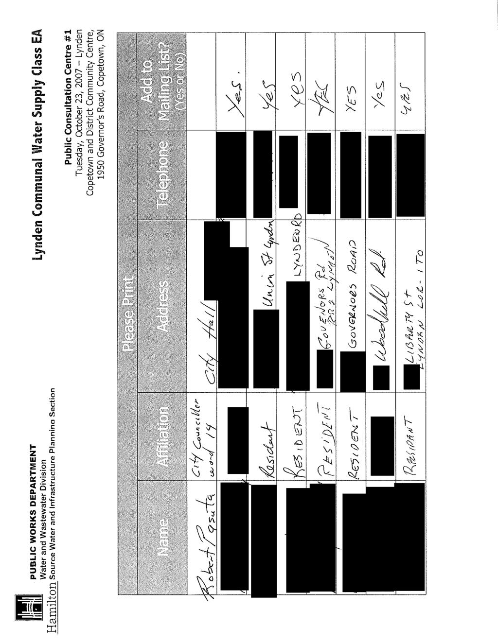
159

160
161
162
163

164
165

166
167
168
169
170 City of Hamilton City Centre, 77 James Street North Hamilton, Ontario, Canada L8R 2K3 Water & Wastewater Division, Public Works Department Physical Address: 55 John Street North, 6 th Floor, Hamilton, Ontario, L8R 3M8 Phone: ext Fax: cshrive@hamilton.ca June 30, 2008 # RR #2 Lynden ON L0R 1T0 Re: Class Environmental Assessment for the Lynden Communal Water Supply Dear Thank you for your attendance at the first Public Information Centre (PIC) regarding the Lynden Communal Water Supply Class Environmental Assessment and for taking the time to complete the comment sheet provided. We are pleased at this time to offer an itemized response to the feedback provided on your comment sheet. Do you have any comments related to the existing water supply in this study area? Not enough water in wells in this area now. If you draw more volume a lot of wells will go dry. The intent of this project is to provide a new well and treatment facility to establish redundancy within the system and thereby increase the security of the water supply. The new well and the existing well will not be pumped simultaneously but will be alternated to meet the demands of the community and allow for the shut down of each facility for maintenance. Withdrawals will remain effectively the same as present under these conditions. As additional connections are made and the demand on the communal water system increases to supply build-out of the Lynden RSA, the permitted pumping capacity will have to be increased from 327 m 3 /day to 411 m 3 /day, an increase of 84 m 3 /day or 15 gallon/min. The increase in the permitted capacity would also apply to the existing well but would only be required when the number of connections to the system warrants additional water supply. This is not anticipated to be for a number of years, but prudent planning practices dictate that this future demand be considered now in the current design of the new facility and the selection of the new well. Studies have shown that the aquifer has sufficient capacity to meet this additional need and this will be further verified during the pump tests to be performed prior to the permitting of the well. The Water Resources Act, 1990 requires that, with the operation of groundwatersourced municipal communal water systems, the municipality must address any interference with private wells. A Permit to Take Water for a new well will not be
171 June 30, 2008 Page 2 granted if potential interference with pre-existing well users is not addressed by the City. To address interference, the City may employ certain mitigation measures at its own expense, such as connecting the affected party to the communal water system or lowering their well pump intakes. If an interference is reported after the permit is issued and the municipal well is operational, the City is still required, as a condition of their PTTW, to take corrective action and either provide connection to the communal water system or lower the private pump intake at the City s cost. In addition, the City of Hamilton s By-Law No (former Ancaster By-law) and a (former Flamborough By-law) provides private well owners a means of petitioning the City if interference occurs, Clause 5 states: The Region agrees to investigate all interferences complaints at Regional expense in conjunction with the Ministry of the Environment staff and to take corrective measures where necessary. In cases where as disruption of water supply has occurred, the Region will arrange for a temporary water supply until a permanent resolution of the problem has been implemented. We understand that no claims have been made of any interference to a private well by the existing municipal well between 1986, when the By-laws were passed, and today. Do you have any comments, concerns, questions or suggestions regarding the Environmental Assessment Process or the overall approach to the project? The Consultants, etc. doing the study don t want to look elsewhere for a water supply (North of Lynden where there is more water). They draw more from same area. The selection of the proposed well site was based on a culmination of over 30 years worth of studies on the hydrogeology of the Lynden area; this includes information already presented in the 2002 Master Plan Class EA. All previous studies have indicated that the sand and gravel aquifer is thickest to the south and east of the Lynden Rural Settlement Area (RSA)., This source has been proven to meet the current requirements of the water service area. Based on mapping of the aquifer thickness and extent, drilling to the north or west would be unsuccessful in securing the required water supply. After the PIC on October 23, 2007, further investigation was undertaken to identify any additional studies that were commissioned by the former Councils. Attempts were also made to contact the previous Mayor of Flamborough and inquires were made again to the Clerk s Office and archives. No additional information or studies were identified beyond those upon which the current work is based, or that indicated a preferred source in another area. On the recommendation of a PIC attendee Johnson and Baetz, a well firm with local experience was contacted and confirmed the presence of a section of sand at the orchard north of the railway tracks. They said that this sand was found at shallow depths, however, extending down only about 3.5 to 4.5 metres. While this sand did produce good volumes of water, they indicated that it would likely not be sufficient for a municipal supply well.
172 June 30, 2008 Page 3 Attached for your reference is a table summarising the reports and studies previously undertaken and reviewed in support of the current study. These documents represent all the relevant investigations undertaken in the area over the past 30 years. Copies of the supporting documentation can be made available for public review, either by appointment or at the next PIC. A summary of the hydrogeological studies will be placed as a link from the Communal Water Studies page on the City s website: icworks/waterandwastewaterdev/reports+and+studies/reportsandstudies.htm Do you have any comments, concerns, questions or suggestions regarding the evaluation criteria for assessment of potential well locations? A desktop evaluation of wells when they were drilled or bored does not give a true picture of what the wells are like now. The purpose of a desktop evaluation prior to the selection of a new well site is twofold: 1. To assess the production capacity of the local wells 2. To assess the material encountered when other local wells were installed. The examination of production capacity of the local wells identifies characteristics of the aquifer. While the original production levels of private wells may have declined over time, the properties of the aquifer that the wells are screened in remain generally constant. The second and more important reason for the desktop evaluation is to examine the materials that were sampled during drilling so as to identify areas where potential aquifers (i.e. sand and gravel) are extensive. The desktop study does not solely examine the properties of the wells, but also materials the driller identified during construction. Private wells can become less efficient over time, but aquifers do not. Examining the initial productivity of a well provides useful clues for selecting the location of a new well and source of groundwater. Do you have any comments, concerns, questions or suggestions regarding the preferred drilling location? They draw more from the same area and lower the water table further. Wells will be greatly affected. As stated above, the Water Resources Act 1990 requires that the municipality must address any interference with private wells. A Permit to Take Water for the new well will not be granted if the City does not address potential interference with preexisting well users. To avoid potential interference, the City may have to employ
173 June 30, 2008 Page 4 certain mitigation measures, such as connection to the communal water system or lowering of pump intakes of private wells at the City s expense. In addition, the City of Hamilton s By-Law No (former Ancaster By-law) and a (former Flamborough By-law) provide private well owners a means of petitioning the City if interference occurs, Clause 5 states: The Region agrees to investigate all interferences complaints at Regional expense in conjunction with the Ministry of the Environment staff and to take corrective measures where necessary. In cases where as disruption of water supply has occurred, the Region will arrange for a temporary water supply until a permanent resolution of the problem has been implemented. We understand that no claims of interference have been made to a private well by the existing municipal well between 1986, when the By-laws were passed, and today. What do you see as the advantages/disadvantages of the proposed project from the perspective of your organization or as a resident of the area? The proposed locations for a backup well don t make sense. They draw more from the same area when the present well is already limited with the supply of water available. The proposed locations for a backup well are based on over 30 years of studies that show that the aquifer is thicker and more extensive to the south and east of Lynden. The studies also show that the aquifer can sustainably provide the required supply of water. Adding a backup well will not create any further drawdowns in the aquifer, since it will not be pumped at the same time as the existing well. As stated above, as additional connections are made and the demand on the communal water system increases, the permitted pumping capacity will have to be increased but studies have shown that the aquifer has sufficient capacity to meet this additional need, this will be further verified during the pump tests preformed prior to the permitting of the proposed new well. Additional comments related to the project. Please investigate north of Lynden and avoid another mistake of not enough water supply as well as affecting all of us in the immediate area. This statement raises three separate issues: 1) Potential Site to the North of Lynden All the previous studies indicated that the sand and gravel aquifer is thickest to the south and east of the Lynden Rural Settlement Area (RSA), and has been proven to meet the current requirements of the water service area. Based on mapping of the aquifer thickness and extent, drilling to the north or west would be unsuccessful in procuring the required water supply. Analysis of driller s logs indicated that the aquifer to the north contained greater proportions of silt and was not as extensive as to the east, where the aquifer is mostly gravel and is of greater extent. Please refer to the attached PIC attendee general response letter for further information on the results of our further investigation into a potential groundwater source north of the RSA. 2) Insufficient Water Supply
174 June 30, 2008 Page 5 The existing well has ample supply to meet the current and future needs of the community. Currently, the well is permitted to pump at 327 m 3 /day; however, the original well testing indicated that the aquifer is capable of providing a safe perennial yield of 560 m 3 /day. 3) Effect of Existing and Proposed Well on Immediate Area As stated above, the Water Resources Act 1990, the City of Hamilton s By-Laws No and a provide private well owners a means of petitioning the City if interference occurs. We understand that no claims of interference to a private well by the existing municipal well were made against these bylaws between 1986, when the By-laws were passed, and today. Please provide any other comments regarding the Public Information Centre (i.e., location, help received on understanding study and your concerns, opportunity provided to ask questions/comments/express concern). Should be held in Lynden. Should have further information when making decision as to location of new backup well (not just desktop information). Arrangements will be made to hold the next PIC in Lynden in Although no date has been set at this time you will be notified of the next meeting well in advance. Please refer to the response above regarding the desktop review. Thank you for volunteering to participate in the Water Well Survey. A sample questionnaire is attached for your review. Once the field program is underway a representative of the City will visit you and will review these questions with you. In addition to our response to your specific concerns, please find attached a letter of response that is being provided to all of the PIC attendees. This letter addresses concerns that were raised by a number of attendees. This letter provides additional background information and is intended to convey a better understanding of the project being undertaken. Thank you again for your interest in this project and providing us with your feedback. If you have any further concerns please contract me directly at (905) ext.7209 or by at cshrive@hamilton.ca. Yours truly, City of Hamilton Chris Shrive, M.Sc., P.Ag. Project Manager /af/db
175 City of Hamilton City Centre, 77 James Street North Hamilton, Ontario, Canada L8R 2K3 Water & Wastewater Division, Public Works Department Physical Address: 55 John Street North, 6 th Floor, Hamilton, Ontario, L8R 3M8 Phone: ext Fax: cshrive@hamilton.ca June 30, 2008 RR2 Lynden ON L0R 1T0 Re: Class Environmental Assessment for the Lynden Communal Water Supply Dear : Thank you for your attendance at the first Public Information Centre (PIC) regarding the Lynden Communal Water Supply Class Environmental Assessment and for taking the time to complete the comment sheet provided. We are pleased at this time to offer an itemized response to the feedback you provided on your comment sheet. Do you have any comments related to the existing water supply in this study area? Does not include enough properties for hook-up outside village. Too much water in Lynden needs sewage service. City By-Law and the Rural Settlement Area (RSA) designations within the Rural Official Plan govern connections to communal water systems. The Lynden RSA boundary was delineated as part of the Flamborough Official Plan and then reviewed in 2006 by the City of Hamilton through its new Rural Official Plan. The bylaw permits lots within the RSA or abutting the RSA to petition to connect; in addition the City of Hamilton By-Law No stipulates that a property abutting a watermain greater than 20mm can also connect. This would apply to all lots fronting the watermain along Governor s Road. This study focuses on meeting the Ministry of the Environment guidelines for drinking water and ensures a safe reliable drinking water supply is provided to the Lynden water service area. We understand that the septic systems and groundwater table in Lynden is an existing issue; however it is not directly related to the project currently being proposed. Although this issue is not included in the scope of this study, additional information on this topic is presented in the general response letter attached. Do you have any comments, concerns, questions or suggestions regarding the Environmental Assessment Process or the overall approach to the project? Need City water not another well.
176 June 30, 2008 Page 2 In 2005, the Greenbelt Act was passed by the Province. This Act, and the associated Greenbelt Plan, identified an area around the Golden Horseshoe and designated it the Greenbelt. The Greenbelt Act ensures the permanent protection of the agricultural land base and the ecological features and functions occurring on this Greenbelt. The Lynden RSA is located within the Greenbelt, therefore is subject to the policies included with the Act. In order to limit development in the Greenbelt and protect the Greenbelt from urban sprawl, the policy outlined in Section of the Greenbelt Plan prohibits the connection of settlements within the Greenbelt to a Great Lake based water system. Where settlements do not currently have Great Lake or Lake Simcoe based water and sewage services, extensions to or expansions of existing Great Lake or Lake Simcoe based services to such settlements is not permitted, unless such servicing is required to address failed individual on-site sewage or water services or to ensure the protection of public health where it has been determined by a medical officer of health (or health authority) that there is a public health concern associated with existing services within the settlement. The capacity of the services provided in the these circumstances will be restricted to that required to service the affected existing settlement plus the capacity for potential development within the approved settlement boundary as it existed on the date this Plan came into effect. Reference: The urban area of City of Hamilton (including Dundas) currently sources its water from the Great Lakes, therefore the extension of the City system to service areas outside of the urban boundary is not permitted accordant with the Greenbelt Plan. An aquifer source can be considered as reliable as a lake based source, although both require prudent management to realize that reliability. Many larger centres in proximity to Lynden rely entirely upon groundwater for water supply. Do you have any comments, concerns, questions or suggestions regarding the evaluation criteria for assessment of potential well locations? How will this affect the existing wells on private property. Do you have any comments, concerns, questions or suggestions regarding the preferred drilling location? Too close to me concerned about my well running dry. The intent of this project is to provide a new well and treatment facility to establish redundancy within the system and thereby increase the security of the water supply. The new well and the existing well will not be pumped simultaneously but will be alternated to meet the demands of the community and allow for the shut down of each facility for maintenance. Withdrawals will remain effectively the same as present under these conditions. As additional connections are made and the demand on the communal water system increases to supply build-out of the Lynden RSA, the permitted pumping capacity will have to be increased from 327 m 3 /day to 411 m 3 /day, an increase of 84 m 3 /day or 15 gallon/min. The increase in the permitted capacity would also apply to the
177 June 30, 2008 Page 3 existing well but would only be required when the number of connections to the system warrants additional water supply. This is not anticipated to occur for a number of years, but prudent planning practices dictate that this future demand be considered now in the current design of the new facility and the selection of the new well. Studies have shown that the aquifer has sufficient capacity to meet this additional need and this will be further verified during the pump tests to be performed prior to the permitting of the well. The Water Resources Act, 1990 requires that, with the operation of groundwatersourced municipal communal water systems, the municipality must address any interference with private wells. A Permit to Take Water for a new well will not be granted if potential interference with pre-existing well users is not addressed by the City. To address interference, the City may employ certain mitigation measures at its own expense, such as connecting the affected party to the communal water system or lowering their well pump intakes. If an interference is reported after the permit is issued and the municipal well is operational, the City is still required, as a condition of their PTTW, to take corrective action and either provide connection to the communal water system or lower the private pump intake at the City s cost. In addition, the City of Hamilton s By-Law No (former Ancaster By-law) and a (former Flamborough By-law) provides private well owners a means of petitioning the City if interference occurs, Clause 5 states: The Region agrees to investigate all interferences complaints at Regional expense in conjunction with the Ministry of the Environment staff and to take corrective measures where necessary. In cases where as disruption of water supply has occurred, the Region will arrange for a temporary water supply until a permanent resolution of the problem has been implemented. We understand that no claims have been made of any interference to a private well by the existing municipal well between 1986, when the By-laws were passed, and today. What do you see as the advantages/disadvantages of the proposed project from the perspective of your organization or as a resident of the area? Does not include enough houses. The City By-Law and the Rural Settlement Area (RSA) plan govern the connections to the communal water system and the priority for connections. The RSA boundary was delineated as part of the Flamborough Official Plan and then reviewed in 2006 by the City of Hamilton. The Greenbelt Act, 2005 does not permit a major expansion to the RSA and only allows minor adjustments to the existing boundaries. Additional comments related to the project. Fear of my well going dry. Want to be put on communal water supply. As addressed in a previous comment, if the new well has been proven to cause unacceptable drawdown in a private well, the City will be immediately required to
178 June 30, 2008 Page 4 provide an alternative water supply or lower the affected well s pump intake at the City s expense. As stated above there are limitations on the connections that can be made to the communal water system, only lots within or abutting the RSA, fronting a watermain or with wells seriously impacted by a municipal well can petition for connection. 72 hours is not long enough to monitor affect on existing wells in area. A 72-hour pumping test is an industry standard implemented informally by the Ministry of the Environment (MOE). A test of this length is sufficient to allow longterm drawdown predictions on existing private wells. Longer tests are not recommended, since precipitation events, which are more likely during longer tests, can obscure potential influence on shallow aquifers. Please provide any other comments regarding the Public Information Centre (i.e., location, help received on understanding study and your concerns, opportunity provided to ask questions/comments/express concern). Very good reception re discussion. Why was it held in Copetown? We have a Legion, a large church hall and the Lion s Den in Lynden which are more convenient for Lynden residents which this whole thing is about!! All future meeting will be held in Lynden. The next PIC will be held in Thank you for volunteering to participate in the Water Well Survey. A sample questionnaire is attached for your review. Once the field program is underway a representative of the City will come to visit you and will review these questions with you. In addition to our response to your specific concerns, please find attached a letter of general response that is being provided to all of the PIC attendees. This letter addresses concerns that were raised by a number of attendees. This letter provides additional background information and is intended to convey a better understanding of the project being undertaken. Thank you again for your interest in this project and providing us with your feedback. If you have any further concerns please contract me directly at (905) ext.7209 or by at cshrive@hamilton.ca. Yours truly, City of Hamilton Chris Shrive, M.Sc., P.Ag. Project Manager /af/db
179 City of Hamilton City Centre, 77 James Street North Hamilton, Ontario, Canada L8R 2K3 Water & Wastewater Division, Public Works Department Physical Address: 55 John Street North, 6 th Floor, Hamilton, Ontario, L8R 3M8 Phone: ext Fax: cshrive@hamilton.ca June 30, 2008 RR #2 Lynden ON L0R 1T0 Re: Class Environmental Assessment for the Lynden Communal Water Supply Dear : Thank you for your attendance at the first Public Information Centre (PIC) regarding the Lynden Communal Water Supply Class Environmental Assessment and for taking the time to complete the comment sheet provided. We are pleased at this time to offer an itemized response to the feedback provided on your comment sheet. Do you have any comments related to the existing water supply in this study area? Not enough water in wells in this area now. If you draw more volume a lot of wells will go dry. The intent of this project is to provide a new well and treatment facility to establish redundancy within the system and thereby increase the security of the water supply. The new well and the existing well will not be pumped simultaneously but will be alternated to meet the demands of the community and allow for the shut down of each facility for maintenance. Withdrawals will remain effectively the same as present under these conditions. As additional connections are made and the demand on the communal water system increases to supply build-out of the Lynden RSA, the permitted pumping capacity will have to be increased from 327 m 3 /day to 411 m 3 /day, an increase of 84 m 3 /day or 15 gallon/min. The increase in the permitted capacity would also apply to the existing well but would only be required when the number of connections to the system warrants additional water supply. This is not anticipated to be for a number of years, but prudent planning practices dictate that this future demand be considered now in the current design of the new facility and the selection of the new well. Studies have shown that the aquifer has sufficient capacity to meet this additional need and this will be further verified during the pump tests to be performed prior to the permitting of the well. The Water Resources Act, 1990 requires that, with the operation of groundwatersourced municipal communal water systems, the municipality must address any interference with private wells. A Permit to Take Water for a new well will not be
180 June 30, 2008 Page 2 granted if potential interference with pre-existing well users is not addressed by the City. To address interference, the City may employ certain mitigation measures at its own expense, such as connecting the affected party to the communal water system or lowering their well pump intakes. If an interference is reported after the permit is issued and the municipal well is operational, the City is still required, as a condition of their PTTW, to take corrective action and either provide connection to the communal water system or lower the private pump intake at the City s cost. In addition, the City of Hamilton s By-Law No (former Ancaster By-law) and a (former Flamborough By-law) provides private well owners a means of petitioning the City if interference occurs, Clause 5 states: The Region agrees to investigate all interferences complaints at Regional expense in conjunction with the Ministry of the Environment staff and to take corrective measures where necessary. In cases where as disruption of water supply has occurred, the Region will arrange for a temporary water supply until a permanent resolution of the problem has been implemented. We understand that no claims have been made of any interference to a private well by the existing municipal well between 1986, when the By-laws were passed, and today. Do you have any comments, concerns, questions or suggestions regarding the Environmental Assessment Process or the overall approach to the project? The Consultants, etc. doing the study don t want to look elsewhere for a water supply (North of Lynden where there is more water). They draw more from same area. The selection of the proposed well site was based on a culmination of over 30 years worth of studies on the hydrogeology of the Lynden area; this includes information already presented in the 2002 Master Plan Class EA. All previous studies have indicated that the sand and gravel aquifer is thickest to the south and east of the Lynden Rural Settlement Area (RSA)., This source has been proven to meet the current requirements of the water service area. Based on mapping of the aquifer thickness and extent, drilling to the north or west would be unsuccessful in securing the required water supply. After the PIC on October 23, 2007, further investigation was undertaken to identify any additional studies that were commissioned by the former Councils. Attempts were also made to contact the previous Mayor of Flamborough and inquires were made again to the Clerk s Office and archives. No additional information or studies were identified beyond those upon which the current work is based, or that indicated a preferred source in another area. On the recommendation of a PIC attendee Johnson and Baetz, a well firm with local experience was contacted and confirmed the presence of a section of sand at the orchard north of the railway tracks. They said that this sand was found at shallow depths, however, extending down only about 3.5 to 4.5 metres. While this sand did produce good volumes of water, they indicated that it would likely not be sufficient for a municipal supply well.
181 June 30, 2008 Page 3 Attached for your reference is a table summarising the reports and studies previously undertaken and reviewed in support of the current study. These documents represent all the relevant investigations undertaken in the area over the past 30 years. Copies of the supporting documentation can be made available for public review, either by appointment or at the next PIC. A summary of the hydrogeological studies will be placed as a link from the Communal Water Studies page on the City s website: icworks/waterandwastewaterdev/reports+and+studies/reportsandstudies.htm Do you have any comments, concerns, questions or suggestions regarding the evaluation criteria for assessment of potential well locations? A desktop evaluation of wells when they were drilled or bored does not give a true picture of what the wells are like now. The purpose of a desktop evaluation prior to the selection of a new well site is twofold: 1. To assess the production capacity of the local wells 2. To assess the material encountered when other local wells were installed. The examination of production capacity of the local wells identifies characteristics of the aquifer. While the original production levels of private wells may have declined over time, the properties of the aquifer that the wells are screened in remain generally constant. The second and more important reason for the desktop evaluation is to examine the materials that were sampled during drilling so as to identify areas where potential aquifers (i.e. sand and gravel) are extensive. The desktop study does not solely examine the properties of the wells, but also materials the driller identified during construction. Private wells can become less efficient over time, but aquifers do not. Examining the initial productivity of a well provides useful clues for selecting the location of a new well and source of groundwater. Do you have any comments, concerns, questions or suggestions regarding the preferred drilling location? They draw more from the same area and lower the water table further. Wells will be greatly affected. As stated above, the Water Resources Act 1990 requires that the municipality must address any interference with private wells. A Permit to Take Water for the new well will not be granted if the City does not address potential interference with preexisting well users. To avoid potential interference, the City may have to employ
182 June 30, 2008 Page 4 certain mitigation measures, such as connection to the communal water system or lowering of pump intakes of private wells at the City s expense. In addition, the City of Hamilton s By-Law No (former Ancaster By-law) and a (former Flamborough By-law) provide private well owners a means of petitioning the City if interference occurs, Clause 5 states: The Region agrees to investigate all interferences complaints at Regional expense in conjunction with the Ministry of the Environment staff and to take corrective measures where necessary. In cases where as disruption of water supply has occurred, the Region will arrange for a temporary water supply until a permanent resolution of the problem has been implemented. We understand that no claims of interference have been made to a private well by the existing municipal well between 1986, when the By-laws were passed, and today. What do you see as the advantages/disadvantages of the proposed project from the perspective of your organization or as a resident of the area? The proposed locations for a backup well don t make sense. They draw more from the same area when the present well is already limited with the supply of water available. The proposed locations for a backup well are based on over 30 years of studies that show that the aquifer is thicker and more extensive to the south and east of Lynden. The studies also show that the aquifer can sustainably provide the required supply of water. Adding a backup well will not create any further drawdowns in the aquifer, since it will not be pumped at the same time as the existing well. As stated above, as additional connections are made and the demand on the communal water system increases, the permitted pumping capacity will have to be increased but studies have shown that the aquifer has sufficient capacity to meet this additional need, this will be further verified during the pump tests preformed prior to the permitting of the proposed new well. Additional comments related to the project. Please investigate north of Lynden and avoid another mistake of not enough water supply as well as affecting all of us in the immediate area. This statement raises three separate issues: 1) Potential Site to the North of Lynden All the previous studies indicated that the sand and gravel aquifer is thickest to the south and east of the Lynden Rural Settlement Area (RSA), and has been proven to meet the current requirements of the water service area. Based on mapping of the aquifer thickness and extent, drilling to the north or west would be unsuccessful in procuring the required water supply. Analysis of driller s logs indicated that the aquifer to the north contained greater proportions of silt and was not as extensive as to the east, where the aquifer is mostly gravel and is of greater extent. Please refer to the attached PIC attendee general response letter for further information on the results of our further investigation into a potential groundwater source north of the RSA. 2) Insufficient Water Supply
183 June 30, 2008 Page 5 The existing well has ample supply to meet the current and future needs of the community. Currently, the well is permitted to pump at 327 m 3 /day; however, the original well testing indicated that the aquifer is capable of providing a safe perennial yield of 560 m 3 /day. 3) Effect of Existing and Proposed Well on Immediate Area As stated above, the Water Resources Act 1990, the City of Hamilton s By-Laws No and a provide private well owners a means of petitioning the City if interference occurs. We understand that no claims of interference to a private well by the existing municipal well were made against these bylaws between 1986, when the By-laws were passed, and today. Please provide any other comments regarding the Public Information Centre (i.e., location, help received on understanding study and your concerns, opportunity provided to ask questions/comments/express concern). Should be held in Lynden. Should have further information when making decision as to location of new backup well (not just desktop information). Arrangements will be made to hold the next PIC in Lynden in Although no date has been set at this time you will be notified of the next meeting well in advance. Please refer to the response above regarding the desktop review. Thank you for volunteering to participate in the Water Well Survey. A sample questionnaire is attached for your review. Once the field program is underway a representative of the City will visit you and will review these questions with you. In addition to our response to your specific concerns, please find attached a letter of response that is being provided to all of the PIC attendees. This letter addresses concerns that were raised by a number of attendees. This letter provides additional background information and is intended to convey a better understanding of the project being undertaken. Thank you again for your interest in this project and providing us with your feedback. If you have any further concerns please contract me directly at (905) ext.7209 or by at cshrive@hamilton.ca. Yours truly, City of Hamilton Chris Shrive, M.Sc., P.Ag. Project Manager /af/db
184 City of Hamilton City Centre, 77 James Street North Hamilton, Ontario, Canada L8R 2K3 Water & Wastewater Division, Public Works Department Physical Address: 55 John Street North, 6 th Floor, Hamilton, Ontario, L8R 3M8 Phone: ext Fax: cshrive@hamilton.ca June 30, 2008 Lynden ON L0R 1T0 Re: Class Environmental Assessment for the Lynden Communal Water Supply Dear : Thank you for your attendance at the first Public Information Centre (PIC) regarding the Lynden Communal Water Supply Class Environmental Assessment and for taking the time to complete the comment sheet provided. We are pleased at this time to offer an itemized response to the feedback provided on your comment sheet. Do you have any comments related to the existing water supply in this study area? It was originally located there because it was the only affordable site at the time. Studies revealed the best water supply was north of the R/R tracks but pricing of land at the time was prohibitive. The selection of the proposed well site was based on a culmination of over 30 years worth of studies on the hydrogeology of the Lynden area; this includes information already presented in the 2002 Master Plan Class EA. All previous studies have indicated that the sand and gravel aquifer is thickest to the south and east of the Lynden Rural Settlement Area (RSA)., This source has been proven to meet the current requirements of the water service area. Based on mapping of the aquifer thickness and extent, drilling to the north or west would be unsuccessful in securing the required water supply. After the PIC on October 23, 2007, further investigation was undertaken to identify any additional studies that were commissioned by the former Councils. Attempts were also made to contact the previous Mayor of Flamborough and inquires were made again to the Clerk s Office and archives. No additional information or studies were identified beyond those upon which the current work is based, or that indicated a preferred source in another area. Attached for your reference is a table summarising the reports and studies previously undertaken and reviewed in support of the current study. These documents represent all the relevant investigations undertaken in the area over the past 30 years.
185 June 30, 2008 Page 2 Copies of the supporting documentation can be made available for public review either by appointment or at the next PIC. A summary of the hydrogeological studies will be placed as a link from the Communal Water Studies page on the City s website: icworks/waterandwastewaterdev/reports+and+studies/reportsandstudies.htm The cost of land is a valid consideration in the process of locating a suitable site for a municipal well, as is the risk and expense associated with conducting a drilling program in an unproven area. In this case the preferred site is within a proven aquifer that has shown to have sufficient capacity to meet the present and future needs of the permitted water servicing area, therefore additional investigation in this area is warranted. Furthermore, the existing well has been in operation for over 20 years and we understand the City has not received any official claims of interference. Do you have any comments, concerns, questions or suggestions regarding the Environmental Assessment Process or the overall approach to the project? It seems to be done in a Distant Vacuum. The well drillers, local (senior) farmers already know where the water is but were not consulted. Former Flamborough Council studies seem to be misplaced. Please refer to the response above. Do you have any comments, concerns, questions or suggestions regarding the evaluation criteria for assessment of potential well locations? It appears a case has been built to justify the dewatering of the existing area instead of consideration of use of the best Lynden water site. As discussed above, the best site for a new well was not located to the north or west of the community, as the sand and gravel aquifer was not as thick or extensive in those areas. These results are based on drilling records dating back more than 50 years. The preferred site is within a proven aquifer that has shown to have sufficient capacity to meet the present and future needs of the permitted water servicing area, therefore additional investigation is not warranted. Furthermore, the existing well has been in operation for over 20 years and the City has not received any official claims of interference. Do you have any comments, concerns, questions or suggestions regarding the preferred drilling location? When the original well was drilled within one year all 3 wells on my farm (prolific for decades) went dry and still are over 20 years later. What guarantees will the City give to those drained this time? The intent of this project is to provide a new well and treatment facility to establish redundancy within the system and thereby increase the security of the water supply.
186 June 30, 2008 Page 3 The new well and the existing well will not be pumped simultaneously but will be alternated to meet the demands of the community and allow for the shut down of each facility for maintenance. Withdrawals will remain effectively the same as present under these conditions. As additional connections are made and the demand on the communal water system increases to supply build-out of the Lynden RSA, the permitted pumping capacity will have to be increased from 327 m 3 /day to 411 m 3 /day, an increase of 84 m 3 /day or 15 gallon/min. The increase in the permitted capacity would also apply to the existing well but would only be required when the number of connections to the system warrants additional water supply. This is not anticipated to be for a number of years, but prudent planning practices dictate that this future demand be considered now in the current design of the new facility and the selection of the new well. Studies have shown that the aquifer has sufficient capacity to meet this additional need and this will be further verified during the pump tests to be performed prior to the permitting of the well. The Water Resources Act, 1990 requires that, with the operation of groundwatersourced municipal communal water systems, the municipality must address any interference with private wells. A Permit to Take Water for a new well will not be granted if potential interference with pre-existing well users is not addressed by the City. To address interference, the City may employ certain mitigation measures at its own expense, such as connecting the affected party to the communal water system or lowering their well pump intakes. If an interference is reported after the permit is issued and the municipal well is operational, the City is still required, as a condition of their PTTW, to take corrective action and either provide connection to the communal water system or lower the private pump intake at the City s cost. In addition, the City of Hamilton s By-Law No (former Ancaster By-law) and a (former Flamborough By-law) provides private well owners a means of petitioning the City if interference occurs, Clause 5 states: The Region agrees to investigate all interferences complaints at Regional expense in conjunction with the Ministry of the Environment staff and to take corrective measures where necessary. In cases where as disruption of water supply has occurred, the Region will arrange for a temporary water supply until a permanent resolution of the problem has been implemented. We understand that no claims have been made of any interference to a private well by the existing municipal well between 1986, when the By-laws were passed, and today. What do you see as the advantages/disadvantages of the proposed project from the perspective of your organization or as a resident of the area? In its urgency to manage risk, we likely will deplete already dry farms to flood Lynden village even more. We already have a severe ground water problem. That significantly worsened over approx. 2 years after the well for Lynden.
187 June 30, 2008 Page 4 Please refer to the response above with respect to the potential for well interference and remedial actions. This study focuses on meeting the Ministry of the Environment guidelines for drinking water and ensures a safe reliable drinking water supply is provided to the Lynden water service area. We understand that the septic systems and groundwater table in Lynden is an existing issue; however it is not directly related to the project currently being proposed. Although this issue is not included in the scope of this study, additional information on this topic is presented in the general response letter attached. Additional comments related to the project. From March to July and Nov. to freeze up, the sump pumps in the older houses in Lynden cycle every 3-15 minutes. The water table is half way up our basement walls. When power goes off, I scramble with generators to a dozen people with their extension cords already stretched out to their driveways for me to run their sump pumps in rotation. We need a plan to drain water out of Lynden before bringing more in. Please refer to the response above and to the attached general PIC attendee letter. Please provide any other comments regarding the Public Information Centre (i.e., location, help received on understanding study and your concerns, opportunity provided to ask questions/comments/express concern). A meeting concerning Lynden should be held in Lynden, not in the next village. All future meetings will be held in Lynden. The next PIC will be held in You may gain some historical geological and water table info from Johnson & Baetz, Princeton. They have drilled this area for decades and have mapping its water consistencies. Johnson and Baetz were contacted and they indicated that they have experience only with shallow bored wells in the Lynden area. They also stated that the shallow overburden geology in the area changes quite rapidly from fine sand to silt to clay, which is in agreement with existing information. Finally, Johnson and Baetz confirmed the presence of a section of sand at the orchard north of the railway tracks. However, they said that this sand was found at shallow depths, extending down only about 3.5 to 4.5 metres. While this sand did produce good volumes of water, they indicated that it would likely not be sufficient for a municipal supply well. In addition to our response to your specific concerns, please find attached a letter of general response that is being provided to all of the PIC attendees. This letter addresses concerns that were raised by a number of attendees. This letter provides additional background information and is intended to convey a better understanding of the project being undertaken. Thank you again for your interest in this project and providing us with feedback on the information presented at the PIC. If you have any further concerns please contract me directly at (905) ext.7209 or by at cshrive@hamilton.ca.
188 June 30, 2008 Page 5 Yours truly, City of Hamilton Chris Shrive, M.Sc., P.Ag. Project Manager /af/db
189 City of Hamilton City Centre, 77 James Street North Hamilton, Ontario, Canada L8R 2K3 Water & Wastewater Division, Public Works Department Physical Address: 55 John Street North, 6 th Floor, Hamilton, Ontario, L8R 3M8 Phone: ext Fax: cshrive@hamilton.ca June 30, 2008 Lynden ON L0R 1T0 Re: Class Environmental Assessment for the Lynden Communal Water Supply Dear : Thank you for your attendance at the first Public Information Centre (PIC) regarding the Lynden Communal Water Supply Class Environmental Assessment and for taking the time to complete the comment sheet provided. We are pleased at this time to offer an itemized response to the feedback you provided on your comment sheet. Do you have any comments related to the existing water supply in this study area? Apparently this well has a great amount of sulphur therefore very costly. Hydrogen sulphide gas can readily be removed by aeration; this process is not very costly. Once a preferred well site has been selected and a test well is installed, a sample of the water will be analysed and any water treatment requirements will be assessed at that time. During the design of the new facility, the hydrogen sulphide removal will be optimized to remove the gas and eliminate odours. Do you have any comments, concerns, questions or suggestions regarding the Environmental Assessment Process or the overall approach to the project? Why can t the City of Hamilton who taxes us very high supply water? City By-Law and the Rural Settlement Area (RSA) designations within the Rural Official Plan govern connections to communal water systems. The Lynden RSA boundary was delineated as part of the Flamborough Official Plan and then reviewed in 2006 by the City of Hamilton through its new Rural Official Plan. The bylaw permits lots within the RSA or abutting the RSA to petition to connect; in addition the City of Hamilton By-Law No stipulates that a property abutting a watermain greater than 20mm can also connect. This would apply to all lots fronting the watermain along Governor s Road. The Ontario Water Resources Act, Clause 34.1, requires the City to provide water to those whose water source is seriously affected by water taking, or to compensate for the costs of doing so.
190 June 30, 2008 Page 2 The above outlines the City s policy on connection to the existing communal system, but the connection of the Lynden RSA to the City of Hamilton water distribution system is regulated by the Greenbelt Act, In 2005 the Greenbelt Act was passed by the Province. This Act, and the associated Greenbelt Plan, identified an area around the Golden Horseshoe and designated it the Greenbelt. The Greenbelt Act ensures the permanent protection of the agricultural land base and the ecological features and functions occurring in this Greenbelt. The Lynden RSA is located within the Greenbelt, and therefore is subject to the policies included with the Act. In order to limit development in the Greenbelt and protect the Greenbelt from urban sprawl, the policy outlined in Section of the Greenbelt Plan prohibits the connection of settlements within the Greenbelt to a Great Lake based water system. Where settlements do not currently have Great Lake or Lake Simcoe based water and sewage services, extensions to or expansions of existing Great Lake or Lake Simcoe based services to such settlements is not permitted, unless such servicing is required to address failed individual on-site sewage or water services or to ensure the protection of public health where it has been determined by a medical officer of health (or health authority) that there is a public health concern associated with existing services within the settlement. The capacity of the services provided in the these circumstances will be restricted to that required to service the affected existing settlement plus the capacity for potential development within the approved settlement boundary as it existed on the date this Plan came into effect. Reference: The urban area of City of Hamilton (including Dundas) currently sources its water from the Great Lakes, therefore the extension of the City system to service areas outside of the urban boundary is not permitted accordant with the Greenbelt Plan. An aquifer source can be considered as reliable as a lake based source, although both require prudent management to realize that reliability. Many larger centres in proximity to Lynden rely entirely upon groundwater for water supply. Do you have any comments, concerns, questions or suggestions regarding the evaluation criteria for assessment of potential well locations? This location has already lowered wells in this area, why put in one more? The Water Resources Act, 1990 requires that, with the operation of groundwatersourced municipal communal water systems, the municipality must address any interference with private wells. A Permit to Take Water for a new well will not be granted if potential interference with pre-existing well users is not addressed by the City. To address interference, the City may employ certain mitigation measures at its own expense, such as connecting the affected party to the communal water system or lowering the affected party s well pump intakes. If interference is reported and confirmed after the permit is issued and the municipal well is operational, the City is still required, as a condition of their PTTW, to take corrective action and either provide connection to the communal water system or lower the private pump intake at the City s cost.
191 June 30, 2008 Page 3 In addition, the City of Hamilton s By-Law No (former Ancaster By-law) and a (former Flamborough By-law) provides private well owners a means of petitioning the City if interference occurs, Clause 5 states: The Region agrees to investigate all interferences complaints at Regional expense in conjunction with the Ministry of the Environment staff and to take corrective measures where necessary. In cases where as disruption of water supply has occurred, the Region will arrange for a temporary water supply until a permanent resolution of the problem has been implemented. We understand that no claims have been made of any interference to a private well by the existing municipal well between 1986, when the By-laws were passed, and today. Do you have any comments, concerns, questions or suggestions regarding the preferred drilling location? Yes, I wish you would find another location; therefore, not jeopardizing farm wells in this area. The selection of the proposed well site was based on a culmination of over 30 years worth of studies on the hydrogeology of the Lynden area; this includes information already presented in the 2002 Master Plan Class EA. All previous studies have indicated that the sand and gravel aquifer is thickest to the south and east of the Lynden Rural Settlement Area (RSA)., This source has been proven to meet the current requirements of the water service area. Based on mapping of the aquifer thickness and extent, drilling to the north or west would be unsuccessful in securing the required water supply. After the PIC on October 23, 2007, further investigation was undertaken to identify any additional studies that were commissioned by the former Councils. Attempts were also made to contact the previous Mayor of Flamborough and inquires were made again to the Clerk s Office and archives. No additional information or studies were identified beyond those upon which the current work is based, or that indicated a preferred source in another area. Attached for your reference is a table summarising the reports and studies previously undertaken and reviewed in support of the current study. These documents represent all the relevant investigations undertaken in the area over the past 30 years. Copies of the supporting documentation can be made available for public review, either by appointment or at the next PIC. A summary of the hydrogeological studies will be placed as a link from the Communal Water Studies page on the City s website: icworks/waterandwastewaterdev/reports+and+studies/reportsandstudies.htm What do you see as the advantages/disadvantages of the proposed project from the perspective of your organization or as a resident of the area? No advantages to me. Possible a big disadvantage if I have to buy water.
192 June 30, 2008 Page 4 Please refer to the response above, if the new well has been proven to cause unacceptable drawdown in a private well, the City will be immediately required to provide an alternative water supply or lower the pump intake at the City s expense. Thank you for volunteering to participate in the Water Well Survey. A sample questionnaire is attached for your review. Once the field program is underway a representative of the City will come to visit you and will review these questions with you. In addition to our response to your specific concerns, please find attached a general letter of response that is being provided to all of the PIC attendees. This letter addresses concerns that were raised by a number of attendees. This letter provides additional background information and is intended to convey a better understanding of the project being undertaken. Thank you again for your interest in this project and providing us with your feedback. If you have any further concerns please contract me directly at (905) ext.7209 or by at cshrive@hamilton.ca. Yours truly, City of Hamilton Chris Shrive, M.Sc., P.Ag. Project Manager /af/db
193 City of Hamilton City Centre, 77 James Street North Hamilton, Ontario, Canada L8R 2K3 Water & Wastewater Division, Public Works Department Physical Address: 55 John Street North, 6 th Floor, Hamilton, Ontario, L8R 3M8 Phone: ext Fax: cshrive@hamilton.ca June 30, 2008 RR2 Lynden ON L0R 1T0 Re: Class Environmental Assessment for the Lynden Communal Water Supply Dear Sir/Madam: Thank you for your attendance at the first Public Information Centre (PIC) regarding the Lynden Communal Water Supply Municipal Class Environmental Assessment. At our October 23, 2007 PIC, we presented details of the project, as well as the preferred drilling location for a new back-up well. At the PIC, a number of issues were raised with respect to the proposed project, as well as some unrelated issues. Issues included: 1. Was a test well already established at the preferred location? 2. The 1987 Ontario Municipal Board (OMB) hearing and its relationship to the current well s permitted pumping capacity limit of 50 gallons/min (327 m 3 /day). 3. An alternative water source north of Lynden. 4. The existing well s effect on surrounding private wells and the potential for a second well to worsen this. 5. Increased well capacity will result in higher consumer water use and overloaded septic systems. Lynden requires a communal sewage system. As these issues were raised by a number of PIC attendees, we are providing further information to all attendees to ensure concerns are adequately addressed. The City of Hamilton is undertaking this project to establish a back-up well and system redundancy in order to meet the requirements of the Ministry of the Environment (MOE) guidelines as well as to ensure that those who are connected to the system and those that can petition to connect continue to be assured of a safe and reliable drinking water supply. The new well and the existing well will not be pumped at the same time but will be alternated to meet the demands of the community and allow for the periodic shut down of each facility for maintenance and improvements as required. Total withdrawals will remain essentially the same as present. As additional connections are made and the demand on the communal water system increases, the permitted pumping capacity for the system may have to be increased, but previous studies have already demonstrated that the aquifer has sufficient capacity to meet this small additional need.
194 These findings will be further verified with additional pump tests performed prior to any permitting of the new well. 1. Was a test well already established at the preferred location? June 30, 2008 Page 2 There was a question as to whether a test well has already been drilled or installed at the preferred location. Based on the documentation review, field investigation and further discussions with the hydrogeologist involved in the drilling of the existing municipal well, it does not appear that there is an existing well on the property or that previous pump testing was performed specifically at the site. 2. The 1987 OMB hearing and its relation to the current well s permitted pumping capacity limit of 50 gallons/min (327 m3/day). At the PIC, reference was made to the 1987 OMB hearing and the relationship to the existing well s permitted pumping capacity limit. In 1987, some area residents petitioned against the Town of Ancaster s request to re-zone the wellsite to allow for drilling and construction of the well and treatment facility, and the matter was heard by the OMB. The petition made by residents to the OMB was dismissed, but in the decision by the Board reference was made to two pre-existing bylaws, By-Law No (former Ancaster By-law) and a (former Flamborough By-law), that were created prior to the OMB hearing. These bylaws set the basis of the application for the Permit To Take Water (PTTW) that provides the interpreted upset limit to watertaking of 327 m3/day. The by-laws further facilitate a due process by which any declared interference to area private wells caused by the operation of the municipal well will be addressed through remedial/restorative measures and/or supply replacement at the (then) Region s cost. In rendering the OMB decision denying the petition, the Board makes reference to the by-laws implementation as over and above the protection that is afforded to well owners under the Ontario Water Resources Act and as evidence that the municipalities have acted responsibly. The City s Legal Department and the Clerk s Office were contacted with respect to the by-laws. We understand that no claims have been made of any interference to a private well by the existing municipal well between 1986 when the By-laws were passed, and today. The Permit to Take Water (PTTW) issued by the Ministry of the Environment (MOE) for the existing well caps the water taking at 327 m 3 /day (50 imperial gallons per minute), which has been the case since the well was drilled. At no time over the operation of the well, has watertaking exceeded this cap. In fact, annual average day demand for the well over the past 10 years have ranged between 118 m3/day and 210 m3/day (annual maximum day between 196 m 3 /day and 235 m 3 /day), with more recent average day demand falling to below 100 m 3 /day. The recent trend may be attributed, in part, to the informal conservation efforts of system users. With future RSA growth from the current 128 connections to a water service area build-out maximum potential of 224 connections, projected average day demands may rise to 181 m 3 /day. The permitted pumping capacity may rise from 327 m 3 /day to 411 m 3 /day in order to accommodate projected maximum day demands. This represents an increase of 84 m 3 /day or 15 gallon/min for maximum day demand. The MOE will have to approve and issue a new PTTW for this change. This growth is not anticipated to occur for some time into the future but good planning practices dictate that the demand potential be considered now in the design of the new facility and the assessment of the new well. Studies have shown that the aquifer has sufficient
195 capacity to meet this additional need; this will be further verified during the pump tests performed on the new well prior to its permitting. 3. An alternative source north of Lynden? June 30, 2008 Page 3 The selection of the proposed well site was based on a culmination of 30 years worth of studies on the hydrogeology of the Lynden area. All the previous studies indicated that the sand and gravel aquifer is thickest to the south and east of the Lynden Rural Settlement Area (RSA), and the aquifer has been proven to meet the current requirements of the water service area. Based on mapping of the aquifer thickness and extent, drilling to the north or west would be unsuccessful in procuring the required water supply. Copies of the supporting documentation can be made available for public review, either by appointment or at the next PIC. A summary of the hydrogeological studies will be placed as a link from the Communal Water Studies page on the City s website: erandwastewaterdev/reports+and+studies/reportsandstudies.htm On the suggestion of one of the PIC attendees, a local drilling company referenced as being familiar with the area was also contacted. The company indicated that they have experience with shallow bored wells in the Lynden area and stated that the shallow overburden geology in the area changes quite rapidly from fine sand to silt to clay, an observation consistent with existing information. The driller confirmed the presence of a section of sand at the orchard north of the railway tracks. The driller further noted, however, that this sand was found at shallow depths extending down only about 3.5 to 4.5 metres from the surface. While this sand may produce good volumes of water, the driller indicated that it would likely not be of a volume sufficient for a municipal supply well. 4. What effect would a new well have on surrounding private wells? Long-term monitoring, testing and operation of the existing well has shown to have had no effect on shallow private wells; this primarily due to the thick clay layer (between 35 m [105 ft] and 50 m [150 ft]) separating the deep aquifer from surficial (shallow) aquifers. With the intent being system back-up and security, the new well and the existing well will not be pumped simultaneously but will be alternated to meet the demands of the community and allow for the shut down of each facility for maintenance. Withdrawals will remain effectively the same as present under these conditions. If the proposed backup causes drawdown in wells screened in the same aquifer or should these private wells lose the ability to produce water, the City, as required by Water Resources Act, 1990, would be responsible at its own expense for rectification of the interference. Options may include the provision of an alternative source of water or lowering the private well intake. In order to have a better understanding of the effect the new well will have on specific wells, the project team will collect details of these wells as part of the Well Survey, and with owner approval undertake to monitor any well before, during and following the pump tests. As stated above, The Water Resources Act, 1990 requires that the municipality must address any interference with private wells. A Permit to Take Water (PTTW) for the new well will not be granted if the City does not address all potential interference with pre-existing well users. To
196 June 30, 2008 Page 4 avoid potential interference, the City may have to employ certain mitigation measures, such as the connection of the affected party to the communal water system or lowering of pump intakes at the City s cost. If interference is reported and confirmed after the permit is issued and the well is operational, the City remains responsible as a condition of the PTTW to take corrective action and either provide connection to the communal water system or lower the private pump intake at the City s cost. 5. Increased system capacity and security will result in higher consumer water use and overloaded septic systems. Lynden requires a communal sewage system. Some RSA residents suggested that the RSA area is subject to a rising water table as a result of an outside water supply and subsequent overuse by RSA residents. As noted in the response to Item 2 above, annual average day demand for the well over the past 10 years has ranged between 118 m 3 /day and 210 m 3 /day, significantly below the PTTW cap of 327 m 3 /day, with more recent average day demand falling to below 100 m 3 /day. The recent trend may be attributed, in part, to the informal conservation efforts of system users. The purpose of the current project is to meet the requirements of the Ministry of the Environment guidelines and to ensure back-up and redundancy in the water system for those who are connected to the system and those that can petition to connect are supplied with safe and reliable drinking water. It is recognized that the septic systems and groundwater table in Lynden is an existing issue; however, it is not related to the project currently being proposed. The issue of the need for a communal sewage system was also raised during the public consultation for the 2002 Master Plan. As part of the Environment Assessment for the Master Plan, the City undertook and provided an examination of the potential costs associated with a communal sewer system. The 2002 Master Plan estimated the total lifecycle costs for providing sewage collection and treatment assuming the cost is shared equitably over the (then-current) 121 water connections as being $2,100,000, or $17,000 per connection. As is the case with the communal drinking water system, the Sustainable Water and Sewage Systems Act and the Municipal Act require the City to seek full cost recovery for communal sewage service. All persons who petition for connection to the system are required to pay a portion of the cost of the system. The City of Hamilton has developed a Wise Water Use Program. Details of the program can be obtained by contacting the City s Community Outreach at , or on the City of Hamilton website at: erandwastewaterdev/education/conservationeducation.htm The program provides details on low flow showerheads, water efficient toilets and other tips to help reduce water use, and therefore alleviate the pressure on over stressed septic system. As indicated above, it should be noted that water use in Lynden has been decreasing over the last three years. The City s Source Water Section, in conjunction with Halton and Hamilton Conservation Authorities, has been conducting information sessions on the management of private wells and septic systems. An information session was held in Lynden this past December. Further sessions
197 June 30, 2008 Page 5 are planned; please refer to the City s website or contact Community Outreach at for more information. Appropriate septic system management is the legal responsibility of the individual owner. The City s Building Department is responsible for identifying and addressing septic system issues in the public s interest through their enforcement of the Ontario Building Code. If a septic system in the area is under capacity or is subject to over-utilization and has the potential to pose a danger to water supply or to human health outside of the property upon which it is located, a report should be made to the City s Building Department ( ) with specifics on the incident, including the address of the suspected source, its nature and frequency. In closing, the City would like to thank you again for your interest in the Lynden Water Supply Class EA Study and for your attendance at the first Public Information Centre. We trust that with the information provided in this letter your comments have been addressed. A second PIC is scheduled for 2008 to provide the test results from the proposed new well location and to consider further design and treatment requirements. We will notify you of its date and location in the coming weeks. Yours truly, City of Hamilton Chris Shrive, M.Sc., P.Ag. Project Manager /af/db
198 City of Hamilton City Centre, 77 James Street North Hamilton, Ontario, Canada L8R 2K3 Water & Wastewater Division, Public Works Department Physical Address: 55 John Street North, 6 th Floor, Hamilton, Ontario, L8R 3M8 Phone: ext Fax: cshrive@hamilton.ca June 16, 2008 RR2 Lynden ON L0R 1T0 Re: Class Environmental Assessment for the Lynden Communal Water Supply Dear Thank you for your attendance at the first Public Information Centre (PIC) regarding the Lynden Communal Water Supply Class Environmental Assessment and for taking the time to complete the comment sheet provided. We are pleased at this time to offer a response to the feedback you provided on the comments sheet. Additional comments related to the project. If project is completed, what would be the cost (projected) for a household hook-up. Further details of the cost to connect will be provided at the second PIC to be held in Lynden in Please provide any other comments regarding the Public Information Centre (i.e., location, help received on understanding study and your concerns, opportunity provided to ask questions/comments/express concern). It would be nice if location closer to Lynden were used The selection of the proposed well site was based on a culmination of over 30 years worth of studies on the hydrogeology of the Lynden area; this includes information already presented in the 2002 Master Plan Class EA. All previous studies have indicated that the sand and gravel aquifer is thickest to the south and east of the Lynden Rural Settlement Area (RSA)., This source has been proven to meet the current requirements of the water service area. Based on mapping of the aquifer thickness and extent, exploring elsewhere would be unsuccessful in securing the required water supply. Thank you for volunteering to participate in the Water Well Survey. A sample questionnaire is attached for your review. Once the field program is underway a representative of the City will come to visit you and will review these questions with you. In addition to our response to your specific concerns, please find attached a general letter of response that is being provided to all of the PIC attendees. This letter addresses concerns that
199 June 16, 2008 Page 2 were raised by a number of attendees. This letter provides additional background information and is intended to convey a better understanding of the project being undertaken. Thank you again for your interest in this project and providing us with your feedback. If you have any further concerns please contract me directly at (905) ext.7209 or by at cshrive@hamilton.ca. Yours truly, City of Hamilton Chris Shrive, M.Sc., P.Ag. Project Manager /af/db
200 City of Hamilton City Centre, 77 James Street North Hamilton, Ontario, Canada L8R 2K3 Water & Wastewater Division, Public Works Department Physical Address: 55 John Street North, 6 th Floor, Hamilton, Ontario, L8R 3M8 Phone: ext Fax: cshrive@hamilton.ca June 30, 2008 P. O. Box Lynden ON L0R 1T0 Re: Class Environmental Assessment for the Lynden Communal Water Supply Dear : Thank you for your attendance at the first Public Information Centre (PIC) regarding the Lynden Communal Water Supply Class Environmental Assessment and for taking the time to complete the comment sheet provided. We are pleased at this time to offer an itemized response to the feedback you provided on your comment sheet. Do you have any comments related to the existing water supply in this study area? Taste is not good at times smells too strongly of chlorine and sometimes of sulphur. After the Walkerton Inquiry, the Safe Drinking Water Act was passed. To meet the disinfection requirements of the Act, chlorine levels at both the source and in the distribution system were increased for the protection of the consumer. Chlorination of the water supply is required to ensure that bacteriological contamination does not occur. The existing well is partially screened in the bedrock below the gravel aquifer, which is the suspected source of the sulphur in the existing well. This issue has been noted and measures will be taken to ensure the proposed well will not be screened in the bedrock in an effort to reduce hydrogen sulphide levels in the water. Do you have any comments, concerns, questions or suggestions regarding the Environmental Assessment Process or the overall approach to the project? I attended the meeting in Copetown and I was discouraged by the lack of background and work done prior to making the proposal. The preferred location presented in the meeting was the result of a culmination of several years of work including information presented in the 2002 Master Plan. Attached for your reference is a table summarising the reports and studies previously undertaken and reviewed in support of the current study. These documents represent all the relevant investigations undertaken in the area over the past 30 years.
201 June 30, 2008 Page 2 Copies of the supporting documentation can be made available for public review, either by appointment or at the next PIC. A summary of the hydrogeological studies will be placed as a link from the Communal Water Studies page on the City s website: icworks/waterandwastewaterdev/reports+and+studies/reportsandstudies.htm After the PIC on October 23, 2007, further investigation was undertaken to identify any additional studies that were commissioned by the former Councils. Attempts were also made to contact the previous Mayor of Flamborough and inquires were made again to the Clerk s Office and archives. No additional information or studies were identified beyond those upon which the current work is based, or that indicated a preferred source in another area. Do you have any comments, concerns, questions or suggestions regarding the evaluation criteria for assessment of potential well locations? The well should be placed to remove water from another area not the same area. There are two reasons for drilling within the same area: There are unnecessary risks and expense in undertaking a drilling program in another area with unproven potential. Based on previous studies dating back more than 30 years, finding a new source outside of the proven area would involve much higher risk, and there are no guarantees that an adequate supply would be found. The primary objective of the present project is to secure back-up to the existing well, and this can be achieved within the existing proven area. The expense of extending the distribution system to another area that might be more distant from Lynden than the preferred option. The proposed locations for a backup well are based on years of studies that show that the aquifer is thicker and more extensive to the south and east of Lynden. The studies also show that this aquifer can sustainably provide the required supply of water. The intent of this project is to provide a new well and treatment facility to establish redundancy within the system and thereby increase the security of the water supply. The new well and the existing well will not be pumped simultaneously but will be alternated to meet the demands of the community and allow for the shut down of each facility for maintenance. Withdrawals will remain effectively the same as present under these conditions. As additional connections are made and the demand on the communal water system increases to supply build-out of the Lynden RSA, the permitted pumping capacity will have to be increased from 327 m 3 /day to 411 m 3 /day, an increase of 84 m 3 /day or 15 gallon/min. The increase in the permitted capacity would also apply to the existing well but would only be required when the number of connections to the system warrants additional water supply. This is not anticipated to be for a number of years, but prudent planning practices dictate that this future demand be
202 June 30, 2008 Page 3 considered now in the current design of the new facility and in the selection of the new well. Studies have shown that the aquifer has sufficient capacity to meet this additional need and this will be further verified during the pump tests to be performed prior to the permitting of the well. Do you have any comments, concerns, questions or suggestions regarding the preferred drilling location? The farmers and residents close to the existing and suggested locations are without water in their wells and not being consulted nor compensated. The City of Hamilton s By-Law No (former Ancaster By-law) and a (former Flamborough By-law) provide private well owners a means of petitioning the City if interference occurs, Clause 5 states: The Region agrees to investigate all interferences complaints at Regional expense in conjunction with the Ministry of the Environment staff and to take corrective measures where necessary. In cases where as disruption of water supply has occurred, the Region will arrange for a temporary water supply until a permanent resolution of the problem has been implemented. We understand that no claims have been made of any interference to a private well by the existing municipal well between 1986, when the By-laws were passed, and today. The Water Resources Act, 1990 requires that, with the operation of groundwatersourced municipal communal water systems, the municipality must address any interference with private wells. A Permit to Take Water for a new well will not be granted if potential interference with pre-existing well users is not addressed by the City. To address interference, the City may employ certain mitigation measures at its own expense, such as connecting the affected party to the communal water system or lowering their well pump intakes. If an interference is reported after the permit is issued and the municipal well is operational, the City is still required, as a condition of their PTTW, to take corrective action and either provide connection to the communal water system or lower the private pump intake at the City s cost. What do you see as the advantages/disadvantages of the proposed project from the perspective of your organization or as a resident of the area? Resident. Doesn t seem to plan for future for expansion enough you neglected to look at previous proposals/plans (from 20 years ago) The proposed well and associated facilities are being designed to meet the long-term requirements for the community. The proposed well will be tested to ensure it can meet the potential long-term demand assuming that all permitted connection are made to the communal water system. Reports dating back over 30 years were used in choosing the location for the proposed well. All the reports reviewed indicated that the best source was to the
203 June 30, 2008 Page 4 south and east of Lynden. Please refer to the responses above with respect to previous studies and planning for additional connections to build-out of the RSA. Additional comments related to the project. It appears that details regarding this project got lost in the amalgamation of Hamilton and Flamborough. The plan from 20 years ago was to have a better facility on the north side of the railroad tracks on Lynden Road. You need to find that study and details. The research has already been done. After the PIC on October 23, 2007, further investigation was undertaken to identify any additional studies that were commissioned by the former Councils. Attempts were also made to contact the previous Mayor of Flamborough and inquires were made again to the Clerk s Office and archives. No additional information or studies were identified beyond those upon which the current work is based, or that indicated a preferred source in another area. Johnson and Baetz, a well firm with local experience, confirmed the presence of a section of sand at the orchard north of the railway tracks. However, they said that this sand was found at shallow depths, extending down only about 3.5 to 4.5 metres. While this sand did produce good volumes of water, they indicated that it would likely not be sufficient for a municipal supply well. They also stated that the shallow overburden geology in the area changes quite rapidly from fine sand to silt to clay, which is in agreement with existing information. Please refer to the response above and the attached table with respect to other previous studies. Please provide any other comments regarding the Public Information Centre (i.e., location, help received on understanding study and your concerns, opportunity provided to ask questions/comments/express concern). I though it was a good first step. It seemed to get a little bit hostile when concerns were not addressed properly. People don t want to get walked all over. One month of study obviously isn t enough. Please refer to the response above and the attached table with respect to previous studies. The selection of the proposed well site was based on a culmination of 30 years of studies on the hydrogeology of the Lynden area, dating back to before the construction of the existing supply well. The studies formed the basis for the selection of preferred site. Need to address the issue of storm sewers. This study focuses on meeting the Ministry of the Environment guidelines for drinking water and ensures a safe reliable drinking water supply system is provided to the Lynden water service area. We understand that the septic system and groundwater table in Lynden is an existing issue; however it is not directly related to the project currently being proposed. Although this issue is not included in the scope of this study, additional information on this topic is presented in the general response letter attached.
204 June 30, 2008 Page 5 Thank you for volunteering to participate in the Water Well Survey. A sample questionnaire is attached for your review. Once the field program is underway a representative of the City will come to visit you and will review these questions with you. In addition to our response to your specific concerns, please find attached a letter of general response that is being provided to all of the PIC attendees. This letter addresses concerns that were raised by a number of attendees. This letter we can provides additional background information and is intended to convey a better understanding of the project being undertaken. Thank you again for your interest in this project and providing us with feedback on the information presented at the PIC. If you have any further concerns please contract me directly at (905) ext.7209 or by at cshrive@hamilton.ca. Yours truly, City of Hamilton Chris Shrive, M.Sc., P.Ag. Project Manager /af/db

205 City of Hamilton City Centre, 77 James Street North Hamilton, Ontario, Canada L8R 2K3 Water & Wastewater Division, Public Works Department Physical Address: 55 John Street North, 6 th Floor, Hamilton, Ontario, L8R 3M8 Phone: ext Fax: cshrive@hamilton.ca June 30, 2008 Lynden ON L0R 1T0 Re: Class Environmental Assessment for the Lynden Communal Water Supply Dear Mr. Post: Thank you for your attendance at the first Public Information Centre (PIC) regarding the Lynden Communal Water Supply Class Environmental Assessment and for taking the time to complete the comment sheet provided. We are pleased at this time to offer an itemized response to the feedback provided on your comment sheet. Do you have any comments related to the existing water supply in this study area? The municipality should extend services to all Lynden residents. City By-Law and the Rural Settlement Area (RSA) designations within the Rural Official Plan govern connections to communal water systems. The Lynden RSA boundary was delineated as part of the Flamborough Official Plan and then reviewed in 2006 by the City of Hamilton through its new Rural Official Plan. The bylaw permits lots within the RSA or abutting the RSA to petition to connect; in addition, the City of Hamilton By-Law No stipulates that a property abutting a watermain greater than 20mm can also connect. This would apply to all lots fronting the watermain along Governor s Road. Based on the address you provided on the comment sheet, you currently reside within the RSA boundary and are connected to the communal water system. The Sustainable Water and Sewage Systems Act, 2002 requires the City to ensure full cost recovery of communal water services; all persons who petition to connect to the system must pay a portion of the cost of the system at the time of connection. Further details of the cost to connect will be provided at the second PIC that will be held in Do you have any comments, concerns, questions or suggestions regarding the Environmental Assessment Process or the overall approach to the project? You should find a way to go back to Dundas for a new line. Heck, Canada was built on cutting down trees!
206 June 30, 2008 Page 2 In 2005 the Greenbelt Act was passed by the Province. This Act, and the associated Greenbelt Plan, identified an area around the Golden Horseshoe and designated it the Greenbelt. The Greenbelt Act ensures the permanent protection of the agricultural land base and the ecological features and functions occurring on this Greenbelt. The Lynden RSA is located within the Greenbelt and subject to the policies included with the Act. In order to limit development in the Greenbelt and protect the Greenbelt from urban sprawl, the policy outlined in Section of the Greenbelt Plan prohibits the connection of settlements within the Greenbelt to a Great Lake based water system. Where settlements do not currently have Great Lake or Lake Simcoe based water and sewage services, extensions to or expansions of existing Great Lake or Lake Simcoe based services to such settlements is not permitted, unless such servicing is required to address failed individual on-site sewage or water services or to ensure the protection of public health where it has been determined by a medical officer of health (or health authority) that there is a public health concern associated with existing services within the settlement. The capacity of the services provided in the these circumstances will be restricted to that required to service the affected existing settlement plus the capacity for potential development within the approved settlement boundary as it existed on the date this Plan came into effect. Reference: The urban area of City of Hamilton (including Dundas) currently sources its water from the Great Lakes, therefore the extension of the City system to service areas outside of the urban boundary is not permitted accordant with the Greenbelt Plan. An aquifer source can be considered as reliable as a lake based source, although both require prudent management to realize that reliability. Many larger centres in proximity to Lynden rely entirely upon groundwater for water supply. Do you have any comments, concerns, questions or suggestions regarding the evaluation criteria for assessment of potential well locations? Seems all locations are bad. Go to north side or west side of Town and extend the service. All the previous studies indicated that the sand and gravel aquifer is thickest to the south and east of the Lynden RSA, and has been proven to meet the current requirements of the water service area. Based on mapping of the aquifer thickness and extent, drilling to the north or west would be unsuccessful in procuring the required water supply. Do you have any comments, concerns, questions or suggestions regarding the preferred drilling location? Why bother drilling anywhere within 2 kms of the original well. There are two reasons for drilling within 2km of the original well: There are unnecessary risks and expense in undertaking a drilling program in another area with unproven potential. Based on previous studies dating back more than 30 years, finding a new source outside of the proven area would involve much higher risk, and there are no guarantees that an adequate supply would be found. The primary objective of the present
207 June 30, 2008 Page 3 project is to secure back-up to the existing well, and this can be achieved within the existing proven area. The expense of extending the distribution system to another area that might be more distant from Lynden than the preferred option. Additional comments related to the project. Go back to the 1980 s when they had a cap on this well pumping limit. So why are you doing this new well so close to the existing one? This statement raises two separate issues :. 1) Cap on the Pumping Limit from the 1980s The Permit to Take Water (PTTW) issued by the Ministry of the Environment (MOE) for the existing well caps the water taking at 3.78 Litres per second (50 imperial gallons per minute), which has been the case since the well was drilled. The intent of this project is to provide a new well and treatment facility to establish redundancy within the system and thereby increase the security of the water supply. The new well and the existing well will not be pumped simultaneously but will be alternated to meet the demands of the community and allow for the shut down of each facility for maintenance. Withdrawals will remain effectively the same as present under these conditions. As additional connections are made and the demand on the communal water system increases to supply build-out of the Lynden RSA, the permitted pumping capacity will have to be increased from 327 m 3 /day to 411 m 3 /day, an increase of 84 m 3 /day or 15 gallon/min. The increase in the permitted capacity would also apply to the existing well but would only be required when the number of connections to the system warrants additional water supply. This is not anticipated to be for a number of years, but prudent planning practices dictate that this future demand be considered now in the current design of the new facility and the selection of the new well. Studies have shown that the aquifer has sufficient capacity to meet this additional need and this will be further verified during the pump tests to be performed prior to the permitting of the well. 2) The Proximity of the Proposed Well to the Existing Well Please refer to the response above regarding the reasoning for selecting a site within a 2km radius of the existing well. Thank you for volunteering to participate in the Water Well Survey. A sample questionnaire is attached for your review. Once the field program is underway a representative of the City will come to visit you and will review these questions with you. In addition to our response to your specific concerns, please find attached a letter of general response that is being provided to all of the PIC attendees. This letter addresses concerns that were raised by a number of attendees. This letter provides additional background information and is intended to convey a better understanding of the project being undertaken.
208 June 30, 2008 Page 4 Thank you again for your interest in this project and providing us with your feedback. If you have any further concerns please contract me directly at (905) ext.7209 or by at cshrive@hamilton.ca. Yours truly, City of Hamilton Chris Shrive, M.Sc., P.Ag. Project Manager /af/db
209 City of Hamilton NOTICE OF PUBLIC INFORMATION CENTER NO 2 CLASS ENVIRONMENTAL ASSESSMENT STUDY LYNDEN COMMUNAL WATER SUPPLY PROJECT BACKGROUND The City of Hamilton has undertaken this study to identify a water supply source to better secure the supply to the Lynden Rural Settlement Area (RSA). Currently, the majority of the Lynden RSA receives its drinking water from a single groundwater well and single storage/treatment facility. The need for the project was identified in 2002 in the Water Master Servicing Plan for the Lynden Rural Settlement Area, which identified the need for additional water supply for the Lynden RSA. THE STUDY PROCESS The study is being completed as a Schedule C Class Environmental Assessment (Class EA). It follows the planning and design process as defined in the Municipal Engineers Association Municipal Class Environmental Assessment document (as amended in 2015). Consultation with and input from the public and review agencies and stakeholders is a vital component of any Class EA study. Members of the public and review agencies are invited to provide comment for incorporation into the overall planning and design of the preferred water supply solution for the Lynden RSA. Upon completion of the study, a Project Report will be available for public review and comment. A Notice of Completion will be published at that time, indicating where and how the public and other stakeholders can obtain access to the report. PUBLIC INFORMATION CENTRE (PIC) NO. 2 A Public Information Centre is being held to present the findings of the study to the public and other stakeholders, and to provide an opportunity for interested parties to provide comments and feedback to the project team. The Public Information Centre will be held: Date: Tuesday, October 18, 2016 Time: 4:30 p.m. to 7:00 p.m. Location: Royal Canadian Legion, 206 Lynden Rd, Lynden ON The purpose of PIC 2 is to review the background and objectives of the study, to communicate the approach to the evaluation of alternatives, present alternative solutions, the preferred design alternative, and to request public input. Information will be presented on display boards and staff from both the City and their consultant will present the information and respond to questions from participants. COMMENTS We are interested in hearing any comments or concerns you may have with respect to this study. A comment sheet/questionnaire will be available for attendees to provide written feedback. Comments received through the course of the study will be considered in selecting the preferred solution. Information will be collected in accordance with the Freedom of the Information and Protection of Privacy Act. With the exception of personal information, all comments will become part of the public record. As part of the consultation process, a mailing list for notification purposes is now being compiled. If you wish to receive further information about this project, to submit a comment, or to be added to the mailing list, please contact: Carmen Vega, Senior Project Manager Michelle Albert, Consultant Source Protection Planning WSP Canada Inc Sustainable Initiatives, Public Works, City of Hamilton 600 Cochrane Dr. Suite James Street North, Suite 400 Markham, Ontario L3R 5K3 Hamilton, ON L8R 2K3 (905) , Ext , Ext Fax: (905) Carmen.Vega@hamilton.ca Michelle.Albert@wspgroup.com Please contact the above regarding requirements for disability accommodation. This Notice published October 7 th and October 14 th, 2016.


210
211 LYNDEN COMMUNAL WATER SUPPLY SYSTEM Schedule C - CLASS EA MUNICIPAL CLASS ENVIRONMENTAL ASSESSMENT FOR LYNDEN COMMUNAL WELL SYSTEM Your Input is Much Appreciated
 Boundary Woodhill Road Lynden Road Governors Road INTRODUCTION Study")
212 LYNDEN COMMUNAL WATER SUPPLY SYSTEM Schedule C - CLASS EA Existing Well New Well Locations Study Area Current Rural Settlement Area (RSA) Boundary Woodhill Road Lynden Road Governors Road INTRODUCTION Study Area


213 LYNDEN COMMUNAL WATER SUPPLY SYSTEM Schedule C - CLASS EA 2002 Master Plan evaluated the Lynden water supply system for the following reasons: Existing PS Capacity Assessment (Meeting the UB Demands) No Redundancy to Ensure a Secure Water Supply High Treated Water Turbidity Preferred Alterative: Upgrade the Existing Pumping Station Upgrade the Existing Well Pumping Station Alternative includes: Treatment for Turbidity Increase capacity to meeting future demand Provide redundancy in water supply source by locating a new well INTRODUCTION Master Plan


214 LYNDEN COMMUNAL WATER SUPPLY SYSTEM Schedule C - CLASS EA The construction of a new well for Lynden Communal Well Supply System requires a Municipal Class EA Schedule C. The objective of the study is: Satisfy the requirement of a Municipal Class Environmental Assessment process to implement a second source of supply for Lynden Communal Well Supply System WSP was retained by the City to complete the Phase 3 and Phase 4 of the Municipal Schedule C Class Environmental Assessment (EA) for Lynden municipal water supply system: Re-Evaluate Preferred Solution from 2002 Master Plan Conduct Hydrogeological Study Conduct Natural and Archaeological Study Provide Design Alternatives & Preferred Design Alternative Phase 1 Problem and Opportunity Phase 2 Alternative Solutions Phase 3 Design Alternatives & Preferred Solution Phase 4 ESR Report Phase 5 Implementation STUDY OBJECTIVE


215 LYNDEN COMMUNAL WATER SUPPLY SYSTEM Schedule C - CLASS EA Public Information Centre (PIC) no.1 was held in October 2011 to obtain public feedback. Summary of the information presented in PIC no.1: Proposed backup well locations; The preferred location for the backup facility; Drilling, well evaluation and monitoring program for the backup well. Public provided their comments and inputs to this Class EA study and response letter was sent out. Hydrogeological Investigation Drilling Program at the Preferred Site YES Well Meets the Demand and Water Quality Requirements? Perform Environmental and Archaeological Assessment Develop Mitigation Measures Finalize Selected Site Develop Treatment Design Options Public Information Centre 2 NO PUBLIC INFORMATION CENTER NO.1
 2015 FDL-03 Raw Water")
216 LYNDEN COMMUNAL WATER SUPPLY SYSTEM Schedule C - CLASS EA 2007 EA Initiation Re-Evaluation of 2002 Master Plan 2008 Extensive Field Investigations 2011 FDL-02 Phase 1 Problem and Opportunity Identify an Alternative Water Supply Source Upgrade the Existing Well System is Still the Preferred Solution Raw Water Requires Treatment for Barium and Hydrogen Sulfide (FDL-02) 2015 FDL-03 Raw Water Requires Treatment for Hydrogen Sulfide (FDL-03) 2016 ESR Report Phase 2 Phase 3 Phase 4 Phase 5 Alternative Solutions Design Alternatives & Preferred Solution ESR Report Implementation OVERVIEW OF THE PROJECT
 1.90 L/s (164 m 3 /d) Max Day Peak Factor - 1.88 Service Connection - 141 Population Capita 451 ADD per Capita L/Cap.")
217 LYNDEN COMMUNAL WATER SUPPLY SYSTEM Schedule C - CLASS EA 2016 Water Demands PARAMETER UNIT VALUE PTTW: Existing Well Water Source 3.8 L/s (FDL-01) (327 m 3 /d) 1.01 L/s Average Daily Demand - Max Daily Demand - (87 m 3 /d) 1.90 L/s (164 m 3 /d) Max Day Peak Factor Service Connection Population Capita 451 ADD per Capita L/Cap./day 193 MDD per Capita L/ Cap./day 363 Number of People per Household Cap./household 3.2 Fire Flow - Not Required Ultimate Buildout Water Demands PARAMETER UNIT VALUE Average Daily Demand 1.68 L/s L/s (ADD) (145 m 3 /d) Max Daily Demand 3.2 L/s L/s (MDD) (273 m 3 /d) Peak Hourly Demand L/s 6.9 L/s (599 m 3 /d) Ultimate Serviced Capita 752 Storage Requirement m m 3 (based on 1.4 mg/l of FCR) Fire Flow Not Required 4% 10% 14% 12% 6% 3% 51% Current RSA Connections Connections Along Governors Rd. Lots Fronting a Distribution Main & Not Connected Lots Not Fronting a Distribution Main & Not Connected Lots Along Governors Rd. Fronting Distribution Main & Not Connected WATER DEMANDS
. Selected location approximately 500 m to the east of FDL-01 for drilling on City owned property.")
218 LYNDEN COMMUNAL WATER SUPPLY SYSTEM Schedule C - CLASS EA Exploration Timeline ( ) Desktop hydrogeological assessment (XCG Consultants, 2006). EA initiated to locate new water supply well (2007). Selected location approximately 500 m to the east of FDL-01 for drilling on City owned property. Ontario Geological Survey (OGS) drilling program (2008) was unsuccessful (aquifer not thick enough). Independent City exploration program at various sites around the community ( ) was unsuccessful in locating a new groundwater source. Purchase of land adjacent to FDL-01 for additional exploration. FDL-02 was drilled in 2011 approximately 100 m south of FDL hour constant rate pumping test o Successfully produced 4.7 L/s. o Water quality concerns: barium (2.7 mg/l), hydrogen sulfide, hardness o Drinking water limit for barium is 1.0 mg/l GROUNDWATER RESOURCES EXPLORATION

 to find a site with lower levels of barium.")
219 LYNDEN COMMUNAL WATER SUPPLY SYSTEM Schedule C - CLASS EA Exploration Timeline (2014) Approximately 125 m south of FDL-02: Step test showed sufficient quantity Water quality concerns: hydrogen sulfide, hardness Barium is not an issue at this location (0.1 mg/l) This location was selected as the preferred site for construction of production well FDL-03. Additional onsite exploration at two locations (2014) to find a site with lower levels of barium. In between FDL-02 and FDL-01: o Step test showed sufficient quantity o Water quality concerns: barium (1.7 mg/l), hydrogen sulfide, hardness GROUNDWATER RESOURCES EXPLORATION
: Pumped at 6.0 L/s for 72 hours. FDL-01 remained in operation.")
220 LYNDEN COMMUNAL WATER SUPPLY SYSTEM Schedule C - CLASS EA Hydraulic Testing of FDL-03 (2016) Variable Rate Step test (March 18, 2016) Tested at pumping rates of 2.5, 5.0, 7.5 and 10.0 L/s to confirm target rate for constant rate test. Constant rate test (March 21-24, 2016): Pumped at 6.0 L/s for 72 hours. FDL-01 remained in operation. Measured water levels in all on-site monitoring wells and four offsite private water wells (2 deep, 2 shallow). Water quality testing at 12 hour intervals Tested for Ontario Drinking Water Quality Sampling parameters (Tables 1-4) including radiological parameters and pesticides just before the end of the test GROUNDWATER RESOURCES EXPLORATION
221 LYNDEN COMMUNAL WATER SUPPLY SYSTEM Schedule C - CLASS EA Hydraulic Testing of FDL-03 (2016) Maximum drawdown of 2.81 m measured in FDL-03 at the end of the test. Minor interference from pumping of FDL-01 (15-25 cm). No interference complaints from adjacent well owners. Zone of influence in deep wells extended m from FDL-03 (1 m of drawdown). No changes in water levels in any shallow wells due to testing. Water quality results: Elevated hydrogen sulfide (typical for the area) Low hardness (soft water) Low levels of barium (well below MOECC objectives) Low levels of lead (well below MOECC objectives) Sodium levels require notification of MOH for sodium restricted diets (typical for the area) Field-measured ph levels were high (typical for the area) GROUNDWATER RESOURCES EXPLORATION
 Well not under influence of surface water (GUDI) based on current")
 will be defined as 100 m radius around FDL-03.")

222 LYNDEN COMMUNAL WATER SUPPLY SYSTEM Schedule C - CLASS EA Hydraulic Testing of FDL-03 (2016) Well not under influence of surface water (GUDI) based on current regulatory guidelines Source water protection implications: Well head protection area A (WHPA-A) will be defined as 100 m radius around FDL-03. Source Protection Plan policies will need to be implemented, especially in WHPA-A. Protection of aquifer from other potential sources of contamination. GROUNDWATER RESOURCES EXPLORATION
223 LYNDEN COMMUNAL WATER SUPPLY SYSTEM Schedule C - CLASS EA Inspection & Clean-Up Program (2009) In 2008, Lynden water supply system experienced a sudden but intermittent rise in lead concentrations that exceeded the ODWS Maximum Allowable Concentration (MAC) of 0.01 mg/l. City conducted further investigation to identify the lead source and mitigating measures Comprehensive cleaning and inspection of the reservoirs; Inspection of all fittings in the reservoir were undertaken to identify potential sources of lead; Removal of the existing air piping inside the chlorination chamber; Replacement of the existing screen/curtains baffles from 1985 inside the reservoir with new baffles in 2009 (cloth material) - Existing baffles were made of a plastic material, traces of lead were found on their surface. Replacement of the well pump (2008): new pump rated for 5.4 L/s capacity at 24m Total Dynamic Head (TDH). LEAD CONCERNS
224 LYNDEN COMMUNAL WATER SUPPLY SYSTEM Schedule C - CLASS EA SYSTEM RATED PUMP CAPACITY MAX DAILY VOLUME Well FDL L/s (467 m³/day) 3.8 L/s (327 m³/day) EXISTING LYNDEN WATER SUPPLY SYSTEM
225 LYNDEN COMMUNAL WATER SUPPLY SYSTEM Schedule C - CLASS EA Alternative 1 Expansion of the Existing PS & Utilizing the Existing Reservoir Design Alternatives Alternative 2 Expansion of the Existing PS & New Reservoir Alternative 3 New PS & New Reservoir Redundancy Utilizing FDL-03 to Provide Source Water Supply DESIGN ALTERNATIVE CONCEPTS
226 LYNDEN COMMUNAL WATER SUPPLY SYSTEM Schedule C - CLASS EA Alternative 1 EXPANSION OF THE EXISTING PUMPING STATION AND UTILIZING THE EXISTING RESERVOIR Refurbishing the Existing well FDL-01; Replacing all Process, Mechanical, Electrical and Instrumentation and Automation Equipment, including Chlorination System, Pumps and Generator; Expansion of the Existing Pumping Station Building to House the New Treatment Equipment; Refurbishing the Existing Reservoir (236 m 3 ); New Treatment System (H 2 S Removal); Connecting Well FDL-03 to the Existing Pumping Station; Decommissioning of the Existing Air Stripping System; Provide Waste Management. DESIGN ALTERNATIVE - 1
227 LYNDEN COMMUNAL WATER SUPPLY SYSTEM Schedule C - CLASS EA Alternative 2 EXPANSION OF THE EXISTING PUMPING STATION AND CONSTRUCTION OF A NEW RESERVOIR Refurbishing the Existing well FDL-01; Replacing all Process, Mechanical, Electrical and Instrumentation and Automation Equipment, including Chlorination System, Pumps and Generator; Expansion of the Existing Pumping Station Building to House the New Treatment Equipment (130 m 3 ); New Treatment System (H 2 S Removal); Constructing a New Reservoir near the Existing PS and Connecting it to the Existing System; Decommissioning of the Existing Aeration Tank and Reservoir; Connecting Well FDL-03 to the Existing Pumping Station; Provide Waste Management. DESIGN ALTERNATIVE - 2
; Constructing a New Reservoir (130 m 3 ); Decommissioning Pumping Station,")
228 LYNDEN COMMUNAL WATER SUPPLY SYSTEM Schedule C - CLASS EA Alternative 3 NEW PUMPING STATION AND NEW RESERVOIR Refurbishing the existing well FDL-01; Constructing a New Pumping Station on the Same Property; Provide Space for a Future Treatment System; New Chlorination System; New Treatment System (H 2 S Removal); Constructing a New Reservoir (130 m 3 ); Decommissioning Pumping Station, Aeration Tank and Reservoir; Connecting Well FDL-03 and FDL-01 to New Pumping Station; Provide Waste Management. DESIGN ALTERNATIVE - 3
 Proximity to")

 Costs Rehabilitation/Replacement Costs Land Acquisition Costs Proximity to Service Area ECONOMIC CONSIDERATIONS TECHNICAL")

229 LYNDEN COMMUNAL WATER SUPPLY SYSTEM Schedule C - CLASS EA SOCIAL & CULTURAL ENVIRONMENT CONSIDERATIONS Proximity to Built-up Areas Traffic Impacts during Construction NATURAL ENVIRONMENT CONSIDERATIONS Crossing Natural Features (wetlands, woodlots) Proximity to Natural Heritage Features/Vegetation Groundwater/Subsurface Conditions Surface Water (Quality/Quantity) Proximity to Valley Lands and Floodplains Watercourse Crossings and Fisheries Known Archaeological Features Private Properties Affected Private Wells Affected Compatibility with Proposed Land Uses Air and Noise Considerations Capital Costs Operation and Maintenance (including energy) Costs Rehabilitation/Replacement Costs Land Acquisition Costs Proximity to Service Area ECONOMIC CONSIDERATIONS TECHNICAL CONSIDERATIONS Ability to Service Future Phases Ability to Provide High Water Quality Constructability and Site Access Soil/Ground Conditions Location and Impacts of Other Utilities Site Size & Compatibility Least Preferred Less Preferred Most Preferred EVALUATION CRITERIA
230 LYNDEN COMMUNAL WATER SUPPLY SYSTEM Schedule C - CLASS EA Alternative Alternative 1 Alternative 2 Alternative 3 Alternative Title Expansion of the Existing Pumping Station and Utilizing the Existing Reservoir Expansion of the Existing Pumping Station and New Reservoir New Pumping Station and New Reservoir Effectiveness Removal of H 2 S, lower treated water turbidity, potential reduction in lead concentration due to reservoir cleaning and removal of sediments. Existing concerns regarding water quality in the reservoir may remain. Sufficient building space to house the potential future treatment processes Water Storage Sufficient Effectiveness Removal of H 2 S, lower treated water turbidity, potential reduction in lead concentration due to using a new reservoir. Sufficient building space to house the potential future treatment processes Water Storage Sufficient Effectiveness Removal of H 2 S, lower treated water turbidity, potential reduction in lead concentration due to reservoir cleaning and removal of sediments. Sufficient building space to house the potential future treatment processes Water Storage Sufficient Ease of operation Filter media backwash; however, easy to operate Ease of operation Filter media backwash; however, easy to operate Ease of operation Filter media backwash; however, easy to operate Technical Impact No available data/report on the possibility of the expansion of the existing building in terms of its condition and DSS report. Existing building is old. No available data/report on the possibility of the expansion of the existing building in terms of its condition and DSS report. Existing building is old. New Building Constructability: Requires shutdown and possibly temporary water supply to the customers. Potential impact on the security of water supply. Potential impact on the water quality during construction period. Risk: High Timeline: Moderate Constructability: Requires shutdown during the operation of the active PS, might disturb water supply to the customers. Potential impact on the security of water supply Potential impact on the water quality during construction period. Risk: Moderate Timeline: Moderate Constructability: Requires minor shutdowns No impact on the operation of the existing PS and reservoir Secure water supply to the customers Risk: Low Timeline: Low-Moderate Redundancy Provided through the Backup Well Rating Least Preferred Less Preferred Most Preferred EVALUATION
231 LYNDEN COMMUNAL WATER SUPPLY SYSTEM Schedule C - CLASS EA Alternative Alternative 1 Alternative 2 Alternative 3 Alternative Title Expansion of the Existing Pumping Station and Utilizing the Existing Reservoir Expansion of the Existing Pumping Station and New Reservoir New Pumping Station and New Reservoir Economic Impact Estimated capital cost - $3.0 million Estimated capital cost - $3.3 million Estimated capital cost $3.8 million O&M Costs $120,000 O&M Costs $120,000 O&M Costs - $120,000 Rating Less Preferred Less Preferred Least Preferred Potential negative impacts associated with chemical supplies Potential negative impacts associated with chemical supplies Potential negative impacts associated with chemical supplies Process wastewater production Process wastewater production Process wastewater production Environmental Impact Minor impact on the environment during construction No negative impact on the aquifer Potential negative impact on storm water drains Minor impact on the environment during construction No negative impact on the aquifer Potential negative impact impact on storm water drains Minor impact on the environment during construction No negative impact on the aquifer Minor impact on storm water drains Rating Less Preferred Less Preferred Most Preferred Social Impact OH&S exposure risks due to chemical usage Maintain the same reservoir which has historically had issues Growth is allowed No impact on private wells OH&S exposure risks due to chemical usage Growth is allowed No impact on private wells OH&S exposure risks due to chemical usage Growth is allowed No impact on private wells Rating Least Preferred Most Preferred Most Preferred Overall Alternative Rating Less Preferred Less Preferred Most Preferred EVALUATION


232 LYNDEN COMMUNAL WATER SUPPLY SYSTEM Schedule C - CLASS EA Notice of Study Commencement October 23, 2007 Water & Wastewater Schedule C Project Public Information Centre No. 1 PHASE 1 Identification of Problem or Opportunity PHASE 2 Evaluation of Alternative Solutions and Identification of Recommended Solution Selection of Preferred Solution following Consultation Activities Evaluation of Alternative Design Concepts for Preferred Solution and Identification of Recommended Design PHASE 3 Selection of Preferred Design after feedback from Consultation Preferred Design Alternative New Pumping Station and New Reservoir We are Here Public Information Centre No. 2 October 18, 2016 PHASE 4 Environmental Study Report PHASE 5 Implementation SCHEDULE C CLASS EA


233 LYNDEN COMMUNAL WATER SUPPLY SYSTEM Schedule C - CLASS EA QUESTIONS? THANK YOU
234
235
236 City of Hamilton City Hall, 71 Main Street West, Hamilton, Ontario, Canada L8P 4Y5 Hamilton Water Division, Public Works Department Physical Address: 77 James Street North, 4 th Floor, Hamilton, Ontario, L8R 3M8 Phone: ext Fax: carmen.vega@hamilton.ca February 21, 2017 Lynden Rd. P.O. Box Hamilton ON L0R 1T0 Re: Class Environmental Assessment for the Lynden Communal Water Supply Dear : Thank you for your attendance at the second Public Information Centre (PIC) on October 18, 2016, regarding the Lynden Communal Water Supply Municipal Class Environmental Assessment and for taking the time to complete the comment sheet provided. Your comments were included in the project documentation and are part of the final project report. Nonetheless we are pleased to offer a response to the feedback provided on your comment sheet. Question: Do you have any comments or concerns regarding the proposed communal water supply? Comment: Private well implications stated no impact, recourse if there is impact. The selection of the proposed well site was based on a culmination of over thirty years worth of studies on the hydrogeology of the Lynden area. This includes information presented in the 2002 Master Plan Class EA and intensive hydrogeological work between 2002 and The preferred well site taps into an aquifer that has shown to have sufficient capacity to meet the present and future needs of the Lynden Rural Settlement Area (RSA). All previous studies have indicated that the sand and gravel aquifer is thickest to the south and east of the RSA. This source has been proven to meet the current requirements of the water service area. Drawdowns in the new well are not expected to be more than 3 meters (10 feet). Drawdowns in nearby private wells are expected to be less than this. All deep wells in the area have large available drawdowns (amount of water in the well). Pumping will not affect levels in the shallow aquifer or shallow wells. Furthermore, the existing well has been in operation for over 30 years and the City has not received any official claims of interference.
237 Page 2 The intent of this project is to provide a new well and treatment facility to establish redundancy within the system and thereby increase the security of the water supply. The new well and the existing well will not be pumped simultaneously but will be alternated to meet the demands of the community and allow for the shut down for maintenance. Withdrawals will remain effectively the same as present under these conditions. Furthermore the Water Resources Act, 1990 requires that, with the operation of groundwater-sourced municipal communal water system, the municipality must address any interference with private wells. A Permit to Take Water (PTTW) for a new well will not be granted if potential interference with pre-existing well users is not addressed by the City. If a potential interference is reported after the permit is issued the City is required as a condition of their PTTW to investigate and to remedy any interference with other water takings that is caused by the water taking under the permit. In addition, the City of Hamilton s By-Law No (former Ancaster By-law) and a (former Flamborough By-law) Clause 4 states: The Region agrees to investigate all interferences complaints at Regional expense in conjunction with the Ministry of the Environment staff and to take corrective measures where necessary. In cases where as disruption of water supply has occurred, the Region will arrange for a temporary water supply until a permanent resolution of the problem has been implemented. We understand that no claims have been made of any interference to a private well by the existing municipal well between 1986, when the By-laws were passed, and today. Thank you again for your interest in this project and providing us with your feedback. If you have any further concerns please contract me directly at (905) ext.1301 or by at carmen.vega@hamilton.ca. Yours truly, Carmen Vega, M. Sc. Senior Project Manager City of Hamilton
238
239
240
241
242
243
244
245
246 City of Hamilton City Hall, 71 Main Street West, Hamilton, Ontario, Canada L8P 4Y5 Hamilton Water Division, Public Works Department Physical Address: 77 James Street North, 4 th Floor, Hamilton, Ontario, L8R 3M8 Phone: ext Fax: carmen.vega@hamilton.ca February 21, 2017 Governors Rd. Lynden, Ontario L0R 1T0 Re: Class Environmental Assessment for the Lynden Communal Water Supply Dear : Thank you for your attendance at the second Public Information Centre (PIC) on October 18, 2016, regarding the Lynden Communal Water Supply Municipal Class Environmental Assessment and for taking the time to complete the comment sheet provided. Your comments were included in the project documentation and are part of the final project report. Nonetheless we are pleased to offer a response to the feedback provided on your comment sheet. Question: Do you have any comments or concerns regarding the proposed communal water supply? Comment: When you put in pumping station all wells on right side of Governor s were affected. We had to put in a new well. What will happen now? Would really like to know. The selection of the proposed well site was based on a culmination of over thirty years worth of studies on the hydrogeology of the Lynden area. This includes information presented in the 2002 Master Plan Class EA and intensive hydrogeological works between 2002 and The preferred site is within an aquifer that has shown to have sufficient capacity to meet the present and future needs of the Lynden Rural Settlement Area (RSA). All previous studies have indicated that the sand and gravel aquifer is thickest to the south and east of the RSA. This source has been proven to meet the current requirements of the water service area. Drawdowns in the new well are not expected to be more than about 3 meters (10 feet). Drawdowns in nearby private wells are expected to be less than this. All deep wells in the area have large available drawdowns (amount of water in the well). Pumping will not affect levels in the shallow aquifer or shallow wells. Furthermore, the existing well has been in operation for over 30 years and the City has not received any official claims of interference.
247 Page 2 The intent of this project is to provide a new well and treatment facility to establish redundancy within the system and thereby increase the security of the water supply. The new well and the existing well will not be pumped simultaneously but will be alternated to meet the demands of the community and allow for the shutdown of each facility for maintenance. Withdrawals will remain effectively the same as present under these conditions. Furthermore the Water Resources Act, 1990 requires that, with the operation of groundwater-sourced municipal communal water system, the municipality must address any interference with private wells. A Permit to Take Water (PTTW) for a new well will not be granted if potential interference with pre-existing well users is not addressed by the City. If a potential interference is reported after the permit is issued the City is required as a condition of their PTTW to investigate and to remedy any interference with other water takings that is caused by the water taking under the permit. Thank you again for your interest in this project and providing us with your feedback. If you have any further concerns please contract me directly at (905) ext.1301 or by at carmen.vega@hamilton.ca. Yours truly, Carmen Vega, M. Sc. Senior Project Manager City of Hamilton
248
249
250
251
252 City of Hamilton City Hall, 71 Main Street West, Hamilton, Ontario, Canada L8P 4Y5 Hamilton Water Division, Public Works Department Physical Address: 77 James Street North, 4 th Floor, Hamilton, Ontario, L8R 3M8 Phone: ext Fax: carmen.vega@hamilton.ca February 21, 2017 Hwy RR Troy Hamilton, Ontario Re: Class Environmental Assessment for the Lynden Communal Water Supply Dear : Thank you for your attendance at the second Public Information Centre (PIC) on October 18, 2016, regarding the Lynden Communal Water Supply Municipal Class Environmental Assessment and for taking the time to complete the comment sheet provided. Your comments were included in the project documentation and are part of the final project report. Nonetheless we are pleased to offer a response to the question provided on your comment sheet. Question: Do you have any comments or concerns regarding the proposed communal water supply? Comment: I am very concerned for our community How does 3 part solutions or alternatives articulate around one well or parcel of land? The selection of the proposed well site was based on a culmination of over thirty years worth of studies on the hydrogeology of the Lynden area. This includes information presented in the 2002 Master Plan Class EA and intensive hydrogeological work between 2002 and The preferred well site taps into an aquifer that has shown to have sufficient capacity to meet the present and future needs of the Lynden Rural Settlement Area (RSA). All previous studies have indicated that the sand and gravel aquifer is thickest to the south and east of the RSA. This source has been proven to meet the current requirements of the water service area. Drawdowns in the new well are not expected to be more than 3 meters (10 feet). Drawdowns in nearby private wells are expected to be less than this. All deep wells in the area have large available drawdowns (amount of water in the well). Pumping will not affect levels in the shallow aquifer or shallow wells. Furthermore, the existing well has been in operation for over 30 years and the City has not received any official claims of interference.
253 Page 2 The intent of this project is to provide a new well and treatment facility to establish redundancy within the system and thereby increase the security of the water supply. The new well and the existing well will not be pumped simultaneously but will be alternated to meet the demands of the community and allow for the shutdown for maintenance. Withdrawals will remain effectively the same as present under these conditions. Thank you again for your interest in this project and providing us with your feedback. If you have any further concerns please contract me directly at (905) ext.1301 or by at carmen.vega@hamilton.ca. Yours truly, Carmen Vega, M. Sc. Senior Project Manager City of Hamilton
254
255
256
257
258 City of Hamilton City Hall, 71 Main Street West, Hamilton, Ontario, Canada L8P 4Y5 Hamilton Water Division, Public Works Department Physical Address: 77 James Street North, 4 th Floor, Hamilton, Ontario, L8R 3M8 Phone: ext Fax: carmen.vega@hamilton.ca February 21, 2017 Lynden Rd. Hamilton ON L0R 1T0 Re: Class Environmental Assessment for the Lynden Communal Water Supply Dear Thank you for your attendance at the second Public Information Centre (PIC) on October 18, 2016, regarding the Lynden Communal Water Supply Municipal Class Environmental Assessment and for taking the time to complete the comment sheet provided. Your comments were included in the project documentation and are part of the final project report. Nonetheless we are pleased to offer a response to the questions on your comment sheet. Question: Do you have any comments or concerns regarding the proposed communal water supply? Comment: Why is the pumping station placed so close to the road? The proposed new municipal well is located more than 200m away from the road. The new pumping station location is yet to be confirmed during detailed design stage. Question: Do you have any other issues or additional information that you feel the City should be made aware of regarding this project? Comment: When will a formal answer on lead in water be announced? Hamilton Water is currently undertaking a Water Treatment Pilot Project that looks further into the treatment options at the new Pumping Station to ensure that lead does not become an issue once the new well is operational. This data will support the Public Health Services in determining when the Drinking Water Advisory can be lifted. We would expect that any change to the Drinking Water Advisory will occur after the new water supply facility is completed in early 2019.
259 Page 2 Thank you again for your interest in this project and providing us with your feedback. If you have any further concerns please contract me directly at (905) ext.1301 or by at carmen.vega@hamilton.ca. Yours truly, Carmen Vega, M. Sc. Senior Project Manager City of Hamilton
260
261
262 From: Sent: To: Subject: Vega, Carmen Tuesday, February 21, :50 PM RE: Lynden Water Hi, Thank you for your attendance at the second Public Information Centre on October 18, 2016, regarding the Lynden Communal Water Supply Municipal Class Environmental Assessment and for taking the time to provide feedback. Your comments were considered and are part of the final project report. As you noted in the below the Greenbelt is the main driver in terms of lake based water supply as the connection of the Lynden Rural Settlement Area to the City of Hamilton water distribution system is regulated by the Greenbelt Act, The Greenbelt Act ensures the permanent protection of the agricultural land base and the ecological features and functions occurring on this Greenbelt. The Lynden RSA is located within the Greenbelt, therefore is subject to the policies included with the Act. In order to limit development in the Greenbelt and protect the Greenbelt from urban sprawl, the policy outlined in Section of the Greenbelt Plan prohibits the connection of settlements within the Greenbelt to a Great Lake based water system. Where settlements do not currently have Great Lake or Lake Simcoe based water and sewage services, extensions to or expansions of existing Great Lake or Lake Simcoe based services to such settlements is not permitted, unless such servicing is required to address failed individual on-site sewage or water services or to ensure the protection of public health where it has been determined by a medical officer of health (or health authority) that there is a public health concern associated with existing services within the settlement. The capacity of the services provided in the these circumstances will be restricted to that required to service the affected existing settlement plus the capacity for potential development within the approved settlement boundary as it existed on the date this Plan came into effect. ( Reference: Section Sewage and Water Infrastructure Policies ) The Lynden RSA is currently serviced by the municipal groundwater based system and therefore the extension of the lake based system to service areas outside of the urban boundary was not the recommended solution in the initial Water Servicing Master Plan for the Lynden RSA (2002, revised 2007). Furthermore in order to achieve a high quality water supply, Hamilton Water is currently undertaking a Water Treatment Pilot Project that looks further into the treatment options at the new Pumping Station to ensure that lead does not become an issue once the new well is operational. This data will support the Public Health Services in determining when the Drinking Water Advisory can be lifted. An aquifer source can be considered as reliable as a lake based source, although both require prudent management to realize that reliability. Many larger centres in proximity to Lynden rely entirely upon groundwater for water supply. Thank you again for your interest in this project and providing us with your feedback.
263 Sincerely, Carmen Carmen Vega, M.Sc. Senior Project Manager Source Protection Planning Sustainable Initiatives Public Works City of Hamilton 77 James Street North, Suite 400 Hamilton, ON L8R 2K3 T: ext From: Sent: October :40 AM To: Vega, Carmen Cc: Pasuta, Robert Subject: Lynden Water Hi Carmen, We recently attended the Lynden water information session. Thank you for taking the time to bring this info out to our town. I am glad that the city takes the supply of safe water so seriously even to a small village like Lynden. I moved to Lynden 24 years ago and this was certainly not the case back then! A ten year stint in Copetown on our own well and cistern provides perspective on the value of someone else providing the water! Last year when a meeting was held here, the question was asked about a pipeline from the city main. We were told that provincial Greenbelt legislation prevents that regardless of how badly city staff would want it. When I asked a staff member about this last week he told me that we don't use enough water here to keep the water from going stagnant in the line. Seeing how in the long run a water line would save the city substantial cost and not involve any more shots in the dark with new wells and treatment systems, I would like to address both of these obstacles. Greenbelt: When a community's health is threatened by lead and other contaminants the province cannot hide behind preserving green space. Certainly local health trumps broad provincial policy. Our greenspace is full of gas and oil pipelines, and hydro corridors but somehow water is a problem!? If they are worried about new development due to the waterline that is simply ridiculous as they decide who can develop and where.
264 Not enough usage: The obvious answer is to allow existing residents along Governors road from Binkley Rd to Lynden road use the water. I also don't quite buy the argument of stale water. If the water took 2 days to get from Copetown to Lynden would it really be bad? We all drink water from bottles that were sealed months ago. They have no chlorine in them and they are fine. Our family currently takes every old container we can find to Sulphur Springs rd every 2 or 3 weeks, fills it, no filter, no additives, and parks it in the garage until we need it. I'd much rather have some of Hamilton's renowned water even it was couple days old! I hope you can find a way to burst through some silly obstacles and bring us some water from an over supplied, high quality water supply that will save us money. A few off the record conversations with water staff, as I have had, might convince you this really is the only long term solution. Thank you for considering this, Park St Lynden
265 LYNDEN WELLS CLASS EA Questions and Responses Log Date Question Question Question Source Date Response Response Response by Status Comments 13-Oct-16 Copies of the PIC material will be forwarded following the PIC meeting on Tuesday (Oct 18). 13-Oct-16 PIC materials (PPTs. Handouts etc.) 23-Oct-16 The information presented at the Public Information Centre is available on-line at Michelle Albert Completed planning/master-plans-class-eas/lynden-communal- water-supply. If you have any questions or comments please do not hesitate to fill in and send us the questionnaire form available at the above mentioned link. 18-Oct Oct Oct-16 PIC materials available online 19-Oct-16 Will the water be brought further down Governors Rd? Pay Hamilton taxes - no Hamilton water services. Why? What would happen to existing wells when new PS is constructed? How does 3 part solutions/alternatives articulate around one well or parcel of land? Long term solution - bring pipe from Hamilton Comment Sheet Comment Sheet Comment Sheet 18-Oct-16 The information presented at the Public Information Centre is now available on-line at We will forward you a copy of the materials presented tonight regarding the Lynden Water System and provide you with information regarding watermain locations and potential extensions. The information presented at the Public Information Centre is now available on-line at Carmen Vega Michelle Albert Carmen Vega Completed Completed 21-Feb-17 Please see response included within Appendix D. Carmen Vega Completed 21-Feb-17 Please see response included within Appendix D. Carmen Vega Completed 21-Feb-17 Please see response included within Appendix D. Carmen Vega Completed A Family of five (3 kids, wife & husband). Currently, trucking water and store it in a cistern. The stored water cannot be drunk as it is not safe. They buy bottles of water for drinking. Drilling a well has a high cost. There are several neighbors that would also be interested in this. When previous PS was constructed, al wells on right side of Governors Rd were affected. This homeowners had to put in a new well. Unsatisfied with the PIC time - too early Homeonwner on private well water 18-Oct-16 Private well implication - stated no impact. Recourse if there is impact Comment Sheet 21-Feb-17 Please see response included within Appendix D. Carmen Vega Completed Landowner resident with 150 feet drilled well in Local Area 18-Oct-16 Why is PS located too close to the road? When will a formal announcement on Lead in water be announced? Comment Sheet 21-Feb-17 Please see response included within Appendix D. Carmen Vega Completed
266 LYNDEN WELLS CLASS EA Questions and Responses Log 24-Oct-16 Property is within the RSA boundary, but currently not connected to the water main. Can the property get hooked up to the water main? Get back with information 28-Oct-16 Thank you for your interest in the Lynden Communal Water Supply study. The information presented at the PIC can be seen by accessing Please find attached a brochure that details the process to be followed in order to extend the municipal water services. The section related to partial services is not a constrain in your case. Carmen Vega Completed The residents were previously told that anyone north of the train tracks cannot be connected. Currently, they take water from 27ft dug well, which is not a problem from October to June. In the summer the well runs dry and they have to call a water truck to fill it every 7 to 10 days at $95 a load. Too costly for residents. With this year (2016) being an especially dry summer, they are still using water truck. 26-Oct-16 Request to bring a pipeline from the City of Hamilton water main 21-Feb-17 Please see response included within Appendix D. Carmen Vega Completed At last year's (2015) meeting, when the question about a pipeline from the city main was asked, residents were told that provincial Greenbelt legislation prevents this. Last week, a City's staff member also said that residents don't use enough water in Lynden RSA to keep the water from going stagnant in the pipeline. The resident addressed both of these obstacles as follows: 1. Greenbelt: When a community's health is threatened by lead and other contaminants the province cannot hide behind preserving green space. Certainly local health trumps broad provincial policy. Our greenspace is full of gas and oil pipelines, and hydro corridors but somehow water is a problem!? If they are worried about new development due to the waterline that is simply ridiculous as they decide who can develop and where 2. Not enough usage: The obvious answer is to allow existing residents along Governors road from Binkley Rd to Lynden road use the water. I also don't quite buy the argument of stale water. If the water took 2 days to get from Copetown to Lynden would it really be bad? We all drink water from bottles that were sealed months ago. They have no chlorine in them and they are fine. Our family currently takes every old container we can find to Sulphur Springs rd every 2 or 3 weeks, fills it, no filter, no additives, and parks it in the garage until we need it. I'd much rather have some of Hamilton's renowned water even it was couple days old!
267 LYNDEN WELLS CLASS EA Questions and Responses Log Estimated timeline no addressed. Preferred option 3 is best as addresses most of issues. 28-Oct-16 Not clear that water pressure conscerned was fully addressed. Is minimum of 50 psi maintained in the distribution system during normal & heavy use periods? Comment Sheet & 21-Feb-17 Comments received. Carmen Vega Completed Other concernes: 1. pressure on well 2. source of lead not determined 3. cost of joining town system 4. how the estimated cost of $4M is handled 28-Nov-16 Residents support the proposal, but they prefer water tower or watermain line from Hamilton. Residents would like to be connected to the new well. Comment Sheet & 21-Feb-17 Comments received. Carmen Vega Completed Residents were excluded from previous water service. Residents concerned that they will not be again connected to the new service.
.")
268 City of Hamilton NOTICE OF STUDY COMPLETION CLASS ENVIRONMENTAL ASSESSMENT STUDY LYNDEN COMMUNAL WATER SUPPLY PROJECT BACKGROUND The City of Hamilton has undertaken this study to identify a water supply source to better secure the supply to the Lynden Rural Settlement Area (RSA). Currently, the majority of the Lynden RSA receives its drinking water from a single groundwater well and single storage/treatment facility. The need for the project was identified in 2002 in the Water Master Servicing Plan for the Lynden Rural Settlement Area. THE STUDY PROCESS The study was completed as a Schedule C Class Environmental Assessment (Class EA). It followed the planning and design process as defined in the Municipal Engineers Association Municipal Class Environmental Assessment document (as amended in 2015). Consultation with the public and government review agencies was carried out by issuing correspondence and holding two Public Information Centres. Members of the public and review agencies were invited to provide comments for incorporation into the overall planning and design of the Lynden Communal Water Supply. The preferred alternative identified in this study includes using a new back-up well (located 200m south of the existing well) and constructing a new pumping station and a new reservoir for the Lynden RSA. PUBLIC REVIEW PERIOD An Environmental Study Report (ESR) was completed which documents the planning process for the study. As required in the Municipal Class Environmental Assessment Process, the Environmental Study Report is being placed on public record for a review period starting March 23, 2017 and ending April 28, It will be available for review at: Location Number 1 Office of the City Clerk 71 Main Street West City Hall, 1 st Floor Hamilton, ON L8R 4Y5 (905) 546-CITY Location Number 2 Public Works Department 77 James Street North Suite 400 Hamilton, ON L8R 2K3 (905) 546-CITY Location Number 3 Lynden Library 110 Lynden Rd Hamilton, ON L0R 1T0 (519) City Website Please contact the City Project Manager regarding disability accommodation requirements as soon as possible. PUBLIC COMMENT PROCESS If concerns arise regarding this project that cannot be resolved directly through discussions with the City of Hamilton, a person/party may request that the Minister of the Environment make an order for the project to comply with Part II of the Environmental Assessment Act (referred to as a Part II Order ). The request for a Part II Order must be received by the Minister by April 28, 2017 with a copy sent to the City s Project Manager at the addresses indicated below. If there are no requests received by this date, the City will proceed with the design and construction of the works identified in the Environmental Study Report. Minister of the Environment and Climate Change 77 Wellesley Street West, 11 th Floor, Ferguson Block Toronto, ON M4V 2T5 Carmen Vega, M.Sc. Senior Project Manager 77 James St. N, Suite 400 Hamilton, ON L8R 2K3 T: x1301 E: Carmen.Vega@hamilton.ca Information will be collected in accordance with the Municipal Freedom of Information and Protection of Privacy Act. With the exception of personal information, all comments will be become part of the public record. This notice was issued on March 23 & March 30, 2017.
269 Appendix E RELTAED STUDIES
270
271 3 February 2004 Tel: File: /10 Fax: City of Hamilton 55 John St. North, 6th Floor Hamilton, ON L8R 3M8 Attention: Ms. Janet Haynes Dear Ms. Haynes:: Reference: Preliminary GUDI Evaluation Lynden Municipal Well FDL01 The City of Hamilton (City) retained Stantec Consulting Inc. (Stantec) to complete a desktop review to determine the status of the groundwater of Municipal Well FDL01 (FDL01) and to provide recommendations for additional work, if required. The evaluation included a review of the following information: Production well and monitoring well logs; Historical raw water quality data from FDL01; Any consultant reports available with respect to the well field; and Regional mapping of the area. All information reviewed as part of this evaluation is referenced in the appropriate sections of this letter. A field inspection was completed on December 8, 2003 to verify the precise locations of the nearest surface water features. Background The following discussion provides a brief history of the communal water supply in Lynden, Ontario. The production well is located south of Governors Road and southeast of Lynden, as shown on Figure 1. The construction and installation of the Lynden well was completed by Morrison Beatty Ltd. in The original report detailing the well installation could not be located. However, the MOE well record (MOE, ) indicates that the Lynden Production well was installed in 1984 to a total depth of 55 m below ground surface (BGS). The well is screened within a sand and gravel aquifer, which is 1 MOE (Ministry of the Environment), Water Well Record, Lynden Well.
272 3 February 2004 Ms. Janet Haynes Page 2 of 7 Reference: Preliminary GUDI Evaluation Lynden Municipal Well FDL01 overlain by clay deposits. The MOE well record indicated that at a pumping rate of 19 L/s, the specific capacity of the well was estimated to be 1.4 L/s/m. Initial production well testing was completed in The original report could not be located, however Morrison ( ) briefly summarized the findings. The 1985 report concluded that the Lynden well could provide a maximum sustainable rate of 3.8 L/s (330 m 3 /day). Prior to well commissioning, a detailed hydrogeologic evaluation was conducted by Morrison (1987). A thirteen (13) day pumping test was performed at a rate of 3.8 L/s to evaluate groundwater quality and quantity from FDL01. Due to concerns of private well interference, twenty (20) private wells were included in the monitoring program. Morrison indicated that water quality from the well was adequate for municipal purposes. By the end of the pumping test, there was no drawdown observed within any shallow monitoring wells in the vicinity of Lynden. Drawdown was noted in observation wells located within the same deep sand and gravel aquifer as the pumping well. Morrison concluded that only minor interference of groundwater quantity occurred within the deep private wells in the area. In 1997, International Water Services (IWS) conducted a well assessment and evaluation (IWS, ). IWS completed a video log, pump inspection and a variable rate pumping test on FDL01. The well inspection did not indicate any problems with casing integrity or plugging of the well screen. The well was step tested at rates of 2.5 L/s to 7.6 L/s. The resulting specific capacity for FDL01 was estimated at 5.5 L/s/m. As required by the MOE, the City contracted MacViro Consultants Inc. (MacViro) to complete an Engineers Report of the Lynden Well System. The report focused on the treatment system, operational procedures and raw water quality (MacViro, ). In 2003, Charlesworth and Associates (Charlesworth) completed a 26-hour pumping test to estimate aquifer parameters and the capture zone of the Lynden well (Charlesworth, ). In addition to monitoring the pumping well, a shallow and a deep observation well was also monitored. The sand and gravel aquifer responded to pumping FDL01 as a confined system. There was no observed response in the shallow monitoring well due to pumping. The average transmissivity of the aquifer was estimated at about 220 m 2 /day. 2 Morrison (Morrison Beatty Ltd.), Well Construction and Testing Program for a Water Supply for the Village of Lynden. Prepared for the Regional Municipality of Hamilton-Wentworth, May IWS (International Water Supply Inc.), Region of Hamilton-Wentworth Well Assessment and Evaluation Study. 4 MacViro (MacViro Consultants Inc.), Engineers Report for the Lynden Well System in the City of Hamilton, January Charlesworth (Charlesworth and Associates), Preliminary Results for Lynden, City Wide Groundwater Study. Prepared for the City of Hamilton.
273 3 February 2004 Ms. Janet Haynes Page 3 of 7 Reference: Preliminary GUDI Evaluation Lynden Municipal Well FDL01 Currently, the Lynden well is operated under Certificate of Approval JG9 and permitted under PTTW 88-P-2000 (Amended) for a maximum pumping rate of 227 L/min (327,312 L/day). Well Construction Production Well FDL01 is located within a concrete brick well house. The well was constructed in 1984 and was completed within the overburden at a total depth of 55 m BGS (MOE, 1984). MacViro (2001) detailed the production well installation. A 305 mm diameter borehole was drilled to 6.0 m BGS. A 200 mm diameter steel outer well casing was installed, extending from approximately 0.6 m above ground surface (AGS) to 50.6 m BGS. The annular space was cement grouted from ground surface to 6.0 m BGS. A 200 mm inner casing extends from 43.9 m BGS to 50.6 m BGS with a stainless steel screen extending 50.6 m to 54.6 m BGS. The screen is composed of 1.5 m lengths of 60 slot, 40 slot and 25 slot screen. The well is equipped with a submersible pump rated for a flow rate of 7.6 L/s at 24 m total dynamic head (TDH). The construction details suggest that FDL01 complies with the current standards O. Reg Site Setting Lynden is located within the Grand River Watershed, approximately 15 km north of the Grand River. The land use in the vicinity of Municipal Well FDL01 is agricultural with residential areas located approximately 1,500 m to the west. Surface topography in the vicinity of Lynden and FDL01 is approximately 235 m AMSL and is relatively flat, as shown on Figures 1 and 2. The ground surface gently slopes to the southwest towards the Grand River at an elevation of 200 m AMSL. The nearest surface water feature in the vicinity of FDL01 is located 250 m to the east and consists of a small unidentified creek approximately 1 m in width flowing in a southerly direction toward the Grand River (Figure 2). Fairchild Creek flows to the southwest towards the Grand River, passing 500 m to the west of FDL01. Two local drainage areas are situated in the vicinity of the FDL01 well house. To the rear of the well house, a shallow depression was created to ensure that any surface runoff is directed away from the well house. Drainage from sampling lines within the well house is also directed to this depression. The second drainage area is a ditch situated north of Governor s Rd., approximately 20 m north of FDL01. At the time of the site inspection, some standing water, approximately 0.1 m in depth, was present in the ditch. The ditch and shallow depression likely receive runoff from major precipitation events but would otherwise normally be dry. Therefore, these two drainage areas are not interpreted to be surface water features. of
274 3 February 2004 Ms. Janet Haynes Page 4 of 7 Reference: Preliminary GUDI Evaluation Lynden Municipal Well FDL01 Geology and Hydrogeology The surficial quaternary geology in the vicinity of Lynden was mapped by Karrow ( ) and is presented in Figure 2. Deposits of glaciolacustrine silt and sand were mapped within Lynden. These sediments represent the Lake Warren shallow water deposits. As part of the City Wide Groundwater Study, Charlesworth (2003) installed a deep monitoring well adjacent to FDL01. The stratigraphy encountered within this well indicates silty sand to sandy silt deposits, extending from ground surface to a depth of 5.7 m BGS. Clayey deposits extend from 5.7 m BGS to 33.5 m BGS forming a thick aquitard overlying sandy silt and fine sand deposits to a depth 46.9 m BGS. The sand and gravel aquifer extends from 46.9 m BGS to the bedrock surface at 55.1 m BGS. This interpretation of the geology is similar to the one provided on the MOE WWR for FDC01, which indicated that clay deposits predominated to a depth of 50 m BGS. Based on MOE Water Well Records for the Lynden area, Morrison (1987) summarized the geology of the area. The report indicated similar stratigraphy to that observed near FDL01. The MOE WWRs indicate surficial deposits of glaciolacustrine deposits of sand and clay extending approximately 3 m BGS underlain by extensive clay till deposits generally greater than 30 m in thickness. Beneath the till are deposits of sand and gravel ranging in thickness from 1.5 m to 20 m. In the vicinity of Lynden, the bedrock surface was encountered at 43 m to 55 m BGS. The bedrock underlying Lynden consists of dolostone of the Lockport Formation of Middle Silurinan in age (MNDM, ). The Lockport Formation is underlain by Ordovician shale. The bedrock elevation decreases from a high of 230 m AMSL to the west of Lynden to 180 m AMSL near FDL01. Municipal Well FDL01 is installed within the deep sand and gravel aquifer, which directly overlies the bedrock. Based on MOE WWR, groundwater flow within the deep aquifer is to the east following bedrock topography. The potentiometric surface of the bedrock and deep aquifer are similar, averaging 14 m BGS. The static water level within FDL01 at the time of installation was 10.4 m BGS (Morrison, 1987). The water table of the shallow aquifer averages 3 m BGS. Aquifer Susceptibility In an effort to quantify the susceptibility of the water supply to contamination, the Intrinsic Susceptibility Index (ISI) was calculated using the method provided in MOE ( ). As 6 Karrow, P.F Pleistocene Geology of the Brantford Area, Southern Ontario. Ontario Department of Mines and Northern Affairs. 7 Ministry of Northern Development and Mines (MNDM), Bedrock Geology of Ontario, Southern Sheet, Map 2544, Scale 1:1,000, Ministry of the Environment (MOE), Groundwater Studies 2001/2002 Technical Terms of Reference, November 2001.
275 3 February 2004 Ms. Janet Haynes Page 5 of 7 Reference: Preliminary GUDI Evaluation Lynden Municipal Well FDL01 indicated in MOE (2001), the ISI for a confined aquifer system is based on the thickness and composition of the overburden material above the first significant aquifer. The ISI is categorized into High (<30), Medium (30 to 80) and Low (>80). A high ISI indicates that the water supply is readily susceptible to contamination, whereas a low ISI indicates that the water supply is less likely to be impacted by onsite activity. For this aquifer, the ISI was calculated to be 150, which indicates that the aquifer has a low intrinsic susceptibility to contamination. Water Quality Historical microbiological results dating back to 1999 were available for FDL01 and are presented in Table 1. The bacteriological results show excellent raw water quality with approximately 2% of samples having detections of total coliforms (5 out of 328). There was 1 sample (out of 328) that had a detection of E.coli. The sample was collected on June 13, 2000 and contained an abnormally high amount of total coliforms, suggesting that it was not a representative sample and may have been contaminated. There were no exceedances of the Ontario Drinking Water Standard (ODWS) for Heterotrophic Plate Count (HPC) analysis (0 out of 64). Historical raw water quality data for FDL01 from June 1997, December 2000 and February 2001 is presented in Table 2. The water quality has been consistent and is characterized by relatively low concentrations of calcium (10 mg/l), chloride (36 mg/l) and sulphate (36 mg/l). Sodium is slightly elevated at a concentration of about 52 mg/l. Raw water from production well FDL01 did not exceed the MOE ODWS Maximum Acceptable Concentration (MAC) for any health-related parameters. The concentration of sodium exceeded 20 mg/l, which is only a concern for consumers who may be on a sodium-restricted diet. Hardness and ph did not meet with the ODWS Operational Guidelines (OG) and aesthetic objectives (AO), respectively. These parameters are not a health-related risk under the ODWS. GUDI Evaluation O. Reg. 903 Section 2(2) provides seven criteria to determine if a water supply system is considered potentially GUDI, as follows: 1. A drinking-water system that obtains water from a well that is not a drilled well or from a well that does not have a watertight casing that extends to a depth of six metres below ground level. 2. A drinking-water system that obtains water from an infiltration gallery. 3. A drinking-water system that is not capable of supplying water at a rate greater than 0.58 L/s and that obtains water from a well, any part of which is within 15 metres of surface water.
276 3 February 2004 Ms. Janet Haynes Page 6 of 7 Reference: Preliminary GUDI Evaluation Lynden Municipal Well FDL01 4. A drinking-water system that is capable of supplying water at a rate greater than 0.58 L/s and that obtains water from an overburden well, any part of which is within 100 metres of surface water. 5. A drinking-water system that is capable of supplying water at a rate greater than 0.58 L/s and that obtains water from a bedrock well, any part of which is within 500 metres of surface water. 6. A drinking-water system that exhibits evidence of contamination by surface water. 7. A drinking-water system in respect of which a written report has been prepared by a professional engineer or professional hydrogeologist that concludes that the system s raw water supply is groundwater under the direct influence of surface water and that includes a statement of his or her reasons for reaching that conclusion. The evaluation criteria that apply to FDL01 are highlighted in italics above. Criteria 1 Municipal Well FDL01 is a drilled well that is cased from above ground surface to approximately 50.6 m BGS. A video inspection of the well was completed by IWS in 1997 and the report (IWS, 1997) did not indicate that the casing was cracked or any signs of leakage. Provided that the integrity of the well casing has not changed since 1997, FDL01 likely satisfies Criteria 1 above. Criteria 4 Municipal well FDL01 is a drilled overburden well that is permitted to supply groundwater at a rate greater than 0.58 L/s (2.3 L/s) and therefore Criteria 4 applies. Criteria 4 states that if a well is located within 100 m of a surface water feature it is considered potentially GUDI. Based on this criterion, FDL01 would not be considered potentially GUDI because the nearest surface water feature is located approximately 250 m to the east of the well. Criteria 6 The key biological indicators of surface water are fecal bacteria, which includes E. coli. Other biological indicators that are not commonly specified in a municipal sampling program include algae, aerobic sporeformers, Giardia, Cryptosporidium and human enteric viruses. Surface water may also exhibit elevated and/or variable concentrations of organic nitrogen, total organic carbon and ph. As discussed above, there was one detection of E. coli in a sample collected from the raw water supply of FDL01 on June 13, However, the sample was not considered representative because there was also an abnormally high concentration of total coliforms. Organic nitrogen is equivalent to Total Kjeldahl Nitrogen (TKN) minus
277 3 February 2004 Ms. Janet Haynes Page 7 of 7 Reference: Preliminary GUDI Evaluation Lynden Municipal Well FDL01 ammonia. TKN was not detected in a single sample of raw water collected in February 2001 (Table 2). The raw water ph has been relatively stable ranging from 8.06 to Dissolved organic carbon was detected in one raw water sample collected in December 2000 at a concentration of 1.1 mg/l; however, concentrations ranging up to 5.0 mg/l are typical of groundwater. No other surface water indicator parameters have been analyzed in the raw samples collected from FDL01. Conclusions Based on the results of the desktop review, FDL01 is not considered potentially GUDI, for the following reasons: In the vicinity of FDL01, the overburden aquifer is confined by a clay and silt aquitard. Based on the depth to the water table and the composition of the overlying material, the susceptibility of the aquifer to contamination from surface was calculated to be 150, which is considered to be low; Results of the 1997 pump testing indicated there was no drawdown observed in the shallow overburden due to pumping of FDL01. The nearest surface water feature to FDL01 is located 250 m to the east, which is further than the minimum distance of 100 m specified in the Safe Drinking Water Act for a well completed in the overburden and capable of supplying more than 0.58 L/s; and The raw water does not exhibit evidence of surface water impacts. Recommendations Based on the desktop review, Municipal Well FDL01 would not be considered potentially GUDI based on the criteria stipulated in the Safe Drinking Water Act and no further investigative work is required. Sincerely, STANTEC CONSULTING LTD. Roger Freymond, P.Eng. Project Manager Craig Johnston, M.Sc. P.Geo. Senior Hydrogeologist Attachment A Figure 1 Site Location Figure 2 Surficial Geology Table 1 Groundwater Bacteriological Results FDL01 Table 2 Raw Water Quality General Chemistry Results FDL01 h w:\active\ \plan ning\report\lynden\ltr_3_feb_04_final lynden.doc
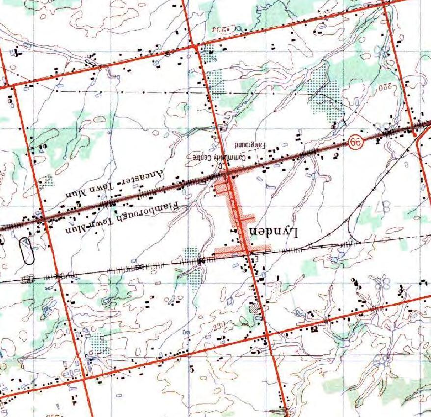
278

279
280 Table 1 Groundwater Bacteriological Results - FDL01 Date Sampled FDL1 (L-5) (Raw Water) Total E.Coli HPC ODWS* 0** 0** 500** City of Hamilton Preliminary GUDI Evaluation, Lynden Municipal Well w:\609\ \planning\data\tbl 1 Lynden FDL01(L-5) bacter data.xls Stantec Consulting Ltd. Project No.: Page 1 of 7
281 Table 1 Groundwater Bacteriological Results - FDL01 Date Sampled FDL1 (L-5) (Raw Water) Total E.Coli HPC ODWS* 0** 0** 500** City of Hamilton Preliminary GUDI Evaluation, Lynden Municipal Well w:\609\ \planning\data\tbl 1 Lynden FDL01(L-5) bacter data.xls Stantec Consulting Ltd. Project No.: Page 2 of 7
282 Table 1 Groundwater Bacteriological Results - FDL01 Date Sampled FDL1 (L-5) (Raw Water) Total E.Coli HPC ODWS* 0** 0** 500** City of Hamilton Preliminary GUDI Evaluation, Lynden Municipal Well w:\609\ \planning\data\tbl 1 Lynden FDL01(L-5) bacter data.xls Stantec Consulting Ltd. Project No.: Page 3 of 7
283 Table 1 Groundwater Bacteriological Results - FDL01 Date Sampled FDL1 (L-5) (Raw Water) Total E.Coli HPC ODWS* 0** 0** 500** City of Hamilton Preliminary GUDI Evaluation, Lynden Municipal Well w:\609\ \planning\data\tbl 1 Lynden FDL01(L-5) bacter data.xls Stantec Consulting Ltd. Project No.: Page 4 of 7
284 Table 1 Groundwater Bacteriological Results - FDL01 Date Sampled FDL1 (L-5) (Raw Water) Total E.Coli HPC ODWS* 0** 0** 500** City of Hamilton Preliminary GUDI Evaluation, Lynden Municipal Well w:\609\ \planning\data\tbl 1 Lynden FDL01(L-5) bacter data.xls Stantec Consulting Ltd. Project No.: Page 5 of 7
285 Table 1 Groundwater Bacteriological Results - FDL01 Date Sampled FDL1 (L-5) (Raw Water) Total E.Coli HPC ODWS* 0** 0** 500** City of Hamilton Preliminary GUDI Evaluation, Lynden Municipal Well w:\609\ \planning\data\tbl 1 Lynden FDL01(L-5) bacter data.xls Stantec Consulting Ltd. Project No.: Page 6 of 7
286 Table 1 Groundwater Bacteriological Results - FDL01 Date Sampled FDL1 (L-5) (Raw Water) Total E.Coli HPC ODWS* 0** 0** 500** Number of Samples: Exceedences: % of Exceedences: 2% 0% 0% Minimum: Maximum: Notes: *Ministry of Environment, Ontario Drinking Water Objectives, August 2000 ** MOE Criteria for Distribution water quality presented for reference purposes only. Does not apply to raw water samples. Cells left blank were not analyzed 2 Parameter exceeds ODWS distribution water quality criteria. City of Hamilton Preliminary GUDI Evaluation, Lynden Municipal Well w:\609\ \planning\data\tbl 1 Lynden FDL01(L-5) bacter data.xls Stantec Consulting Ltd. Project No.: Page 7 of 7
287 Table 2 Raw Water Quality General Chemistry Results - FDL01 Sample Location: FDL01 FDL01 FDL01 FDL01 FDL01 Sample I.D: MOE Raw Treaded Sampled By: Ontario Drinking Units MOE Reference Job Number: Water Sample Date: Standards 10-Jun-97 Dec Feb Sep Feb-01 Metals Aluminum 0.1 OG mg/l < 0.03 < Antimony n/v mg/l - - < < Arsenic IMAC mg/l < < < Barium 1.0 MAC mg/l Beryllium n/v mg/l < < Bismuth n/v mg/l < 0.1 < Boron 5.0 IMAC mg/l Cadmium MAC mg/l < < Calcium n/v mg/l Chromium 0.05 MAC mg/l < < Cobalt n/v mg/l < < Copper 1.0 AO mg/l Cyanide - Total n/v mg/l - - < < < Iron 0.30 AO mg/l < Lead 0.01 MAC mg/l < < < Magnesium n/v mg/l Manganese 0.05 AO mg/l Mercury n/v mg/l < < < Molybdenum n/v mg/l < 0.01 < Nickel n/v mg/l < Potassium n/v mg/l < 0.9 < 0.9 Reactive Silica n/v mg/l Selenium 0.01 MAC mg/l - - < < < Silver n/v mg/l < < Sodium 20 MOH/200 AO mg/l Strontium n/v mg/l Thallium n/v mg/l < 0.11 < Tin n/v mg/l < 0.01 < Titanium n/v mg/l < Uranium 0.02 MAC mg/l < < Vanadium n/v mg/l < < Zinc 5.0 AO mg/l General Chemistry Alkalinity (as CaCO3) OG mg/l Ammonia (as N) n/v mg/l < Chloride (as Cl) 250 AO mg/l Nitrate (as N) 10 MAC mg/l < 0.15 < 0.03 < 0.03 Nitrite (as N) 1 MAC mg/l < 0.15 < 0.03 < 0.03 Total Kjeldahl Nitrogen as N n/v mg/l - - < Sulphate 500 AO mg/l Fluoride n/v mg/l Dissolved Organic Carbon (DOC) 5.0 AO mg/l < Anion Sum n/v mg/l Bicarbonate(as CaCO3, calculated) n/v mg/l Carbonate (as CaCO3), calculated) n/v mg/l Cation Sum n/v meq/l Hardness (as CaCO3) OG mg/l Ion Balance nv % Langeliers Index at 20 C nv na Langeliers Index at 4 C nv na Saturation ph at 20 C nv Std. Units Saturation ph at 4 C nv Std. Units Total Dissolved Solids 500 AO mg/l ºC n/v µs/cm ph AO Std. Units Colour 5 AO TCU 5 - < 5 < 5 < 5 Turbidity 1.0(MAC) NTU Notes: Ministry of the Environment, Ontario Drinking Water Standards (ODWS), (June, 2003) nv no guideline available AO Aesthetic Objective that relates to either the taste, odour or appearance of water IMAC Interim Maximum Acceptable Concentration (IMAC) MAC Maximum Acceptable Concentration (MAC) OG Operational Guidelines which usually relates to municipal water treatment 85 Parameter exceeds MOE ODWS 98 Parameter exceeds Medical Officer of Health (MOH) City of Hamilton Preliminary GUDI Evaluation, Lynden Municipal Well w:\609\ \planning\analysis\data\table 2 FDL01 Inorganic chemistry.xls Stantec Consulting Ltd. Project No.: Page 1 of 1
288 TECHNICAL MEMORANDUM Date: October 4, 2007 To: Chris Shrive, City of Hamilton Copies: Gary Scott; Muin Husain; Alicia Fraser; From: Derek Brunner Project No.: MA MA Subject: Evaluation of Alternatives for Potential Well Locations 1. Background In the summer of 2002 the City of Hamilton developed a Comprehensive Water Servicing Master Plan for the Lynden Rural Settlement Area (Servicing Master Plan). The Plan considered the need for additional water supply to the Rural Settlement Area (RSA) and compared various general methods of meeting the requirement of the future RSA. One of the alternatives identified was to drill a new municipal supply well to provide this extra water and also to provide redundancy when combined with the existing well (FLD01). As such, a Schedule C Class Environmental Assessment (EA) was initiated, part of which is to examine alternative locations for the placement of a new well. This technical memorandum briefly reviews the site locations identified in the XCG (2006) report, and evaluates a sixth alternative based on the same criteria. 2. Geology / Hydrogeology The regional geology in the Lynden area consists of surficial deposits of glaciolacustrine sands with some silt of variable thickness. MOE well records and borehole logs indicate that there is a thin veneer of sands and silts overlying a clay till aquitard at least 30m thick. Sand and gravel deposits underlie the till and form a regional aquifer. Dolostone bedrock of the Lockport formation lies below the sand and gravel aquifer. It is believed that the bedrock is a source of hydrogen sulphide, which makes it undesirable for a drinking water supply. Locally, the till layer has been estimated at up to 50m in thickness, and the underlying gravel aquifer ranges from less than a meter to 5m thick. 3. Well Location Criteria Five potential locations for municipal supply wells were investigated by XCG (2006). As part of this study, a number of criteria were provided to determine which location is most suitable for a new well. These criteria include: Probability of new well being capable of supplying greater than 5 L/s Proximity to Lynden Proximity to distribution system City owned land MARKHAM 600 Cochrane Drive, Suite 500, Markham, Ontario L3R 5K3 Tel.: (905) Fax: (905) H:\6333\HydroG\Tech Memo - Site Selection\Evaluation of Alternatives for Potential Well Locations.doc
289 Technical Memorandum Page 2 Potential for GUDI Predicted Intrinsic susceptibility index Well interference potential Physical constraints Potential impacts on surface water bodies Water quality A description of each of these criteria is included in Table 3-1 (XCG, 2006). 4. Potential Well Locations The report by XCG (2006) identified five potential locations for a municipal supply well for the Community of Lynden. In addition to these five locations, a sixth potential location was identified in August 2007 on land that was owned by the City of Hamilton. This location has been designated as Alternative F for the purposes of this report. A brief discussion of the alternatives is presented below. Alternative F is discussed in more detail in the same format as the XCG (2006) report. The available alternatives are summarized in Table 4-1, which has been revised from Table 6 in the XCG (2006) report. 4.1 Existing Alternatives XCG (2006) described five alternative well locations for potential water supply in the Community of Lynden. They summarized that sites A, B, C, and E were equal in terms of many of the criteria, with site E being preferred due to proximity to Lynden and distance from the existing supply well, which would provide security in the event of aquifer contamination. Location D was ranked the lowest due to physical constraints and lower potential for finding the required 5 L/s. More detailed discussions of each of the alternatives can be found in the hydrogeological investigation by XCG (2006). Locations of the alternatives are shown in Figure Alternative F Site Alternative F is located on the north side of Governor s Road approximately 500m east of the existing production well (Figure 1). This site was chosen partly because the land was owned by the City of Hamilton, the interpreted thickness of the gravel layer, its proximity to Lynden and the distribution system. However, the following section provides a hydrogeological analysis of the Alternative F site Hydrogeological Considerations for Alternative F Site Based on the available information, the gravel aquifer at the location of Alternative F is expected to be between 0-1m in thickness (XCG, 2006), compared with approximately 4m in the vicinity of the existing well (Figure 2). Therefore, an analysis was conducted to assess whether or not an aquifer of 1m or less thickness could provide a sustainable yield of 5 L/s. As part of the assessment, the Theis equation was used with the following assumptions: H:\6333\HydroG\Tech Memo - Site Selection\Evaluation of Alternatives for Potential Well Locations.doc
290 Technical Memorandum Page 3 The transmissivity of the aquifer varies between 196m 2 /day and 244m 2 /day based on the range provided by XCG (2006). Aquifer thickness varied between 0.5 1m as reported by XCG (2006). Storativity for a confined aquifer = 1x10⁻⁴ Required pumping rate = 5 L/s as per the requirement of the system. The maximum drawdown in the pumping well and at distances of 100m and 500m were estimated for a 20-year period (as in the XCG (2006) report). The results are summarized in Table 4-2. The calculations are summarized in Appendix A. Table 4-2 Aquifer Thickness (m) Drawdowns in Proposed Pumping Well for Different Aquifer Thicknesses Transmissivity for 4m Thick Aquifer (m 2 /day) Equivalent Transmissivity for Thinner Aquifer (m 2 /day) Drawdown in 20 years (m) Drawdown at 20 years (m) Drawdown at 500m@ 20 years (m) It should be noted that the transmissivity values were only available in areas where the aquifer was approximately 4m thick. In order to make a proper extrapolation of the potential drawdowns in the location of Alternative F, the transmissivity in the area was normalized to the thickness of the aquifer. It did not appear that this was performed by XCG (2006) when estimating the longterm impacts on nearby private wells. It is possible that for the locations where the aquifer is thin, their calculations may have underestimated the drawdowns. It should also be noted that although the predicted thickness of the aquifer in the area was estimated to be between 0-1m, it is possible that these contours are based only on two points on either side of the site location. Assuming that the proposed production well has a similar available drawdown as the current production well (i.e. between 40-45m), after 20 years an aquifer 0.5 thick would experience drawdowns between m, while a 1m thick aquifer would experience drawdowns between m at the pumping well. The drawdown levels after 20 years at a distance of 100m from the pumping well are estimated to be between m for an aquifer 0.5m thick and between m for an aquifer 1.0m thick. The drawdown levels after 20 years at a distance of 500m from the pumping well are estimated to be between m for an aquifer 0.5m thick and between m for an aquifer 1.0m thick. Based on the information in the XCG (2006) report, most of the private wells screened in the gravel in the area have available drawdowns of over 30m. It should be noted that if the aquifer pinches out in any direction, drawdowns in the pumping well would increase. This should be expected, since two boundaries were encountered during a 24-hour pumping test in December 1984 (Morrison Beatty, 1985) Evaluation of Alternative F Four potential concerns were noted for Alternative F. The limited thickness of the aquifer, predicted by XCG (2006), will have a lower transmissivity, which will lead to greater drawdowns for the same pumping volume. There is also the possibility of encountering an H:\6333\HydroG\Tech Memo - Site Selection\Evaluation of Alternatives for Potential Well Locations.doc
291 Technical Memorandum Page 4 aquifer boundary, which will further increase the drawdowns. The increased drawdowns may cause issues regarding potential interference with private water well users. Alternative F was also evaluated using the criteria described by XCG (2006) in Table 4-1. The site is approximately 2,000m from Lynden, which is the second furthest location of the alternatives. It is also approximately 140m from the distribution system. The potential for GUDI at this site was estimated to be low based on the distance to the nearest surface water body being greater than 100m and the Intrinsic Susceptibility Index (ISI) of nearby wells being greater than 80 (XCG, 2006). It is also likely that the thick clay till will provide an effective buffer against surface water infiltration. The potential for physical constraints was estimated to be low based on ortho-photography and a site visit (i.e. site access). The potential for impact on nearby wells was also estimated to be manageable, based on the predicted drawdowns calculated in the previous section. The potential for impact on surface water bodies was estimated to be low, based on the ISI of wells in the vicinity of the surface water bodies and the thickness of the intervening clay layer. Based on the limited chemical data available from MOE well records, the water quality has a higher probability of being fresh if screened in the gravel aquifer. 5. Recommendations Based on the hydrogeological assessment, this site has the potential to provide a sustainable yield of 5 L/sec with the following assumptions: The aquifer is 1m thick or greater. The aquifer transmissivity and storativity values at the proposed location are similar to those in the thicker portions of the aquifer. No boundary effects are encountered. 5.1 Comparison with Other Alternatives An evaluation was conducted for Alternative F against each of the defined criteria from XCG (2006) and compared with the other wells. Alternative F compares favourably with the other alternatives with respect to potential to meet the required demand, low GUDI potential, low predicted ISI, no physical constraints, low potential impact on surface water bodies, and probability of water quality. This alternative does not compare favourably with the preferred alternatives A and E with respect to distance to Lynden and the distribution system and with potential impacts to nearby wells due to the predicted thickness of the aquifer. However, Alternative F has the strategic advantage of being on land owned by the City of Hamilton. This advantage would allow test well construction immediately without having to undergo the potentially time consuming and expensive process of procuring additional property. In the event that the aquifer in the proposed location is unable to provide the required pumping volumes, it is recommended that the secondary site identified in the XCG (2006) report (Alternative E) be explored further. H:\6333\HydroG\Tech Memo - Site Selection\Evaluation of Alternatives for Potential Well Locations.doc
292 Legend Potential Well Location Watermain Roadway Railway Watercourse Pressure District Boundary 2000 m radius Concession 2 West Weir Road Weir Road D E A B F C Governors Road Field Road Lynden Road Powerline Road km


293 Legend Roads Railway Line Surface Water Body Pressure District Boundary Watermains 2000 m radius D WELL FDL01 A B E C 3 Potential Well Locations Municipal Well FDL01 2 Gravel Unit Thickness (m) ALL POTENTIAL WELL LOCATIONS FOR A NEW MUNICIPAL WELL LYNDEN WELL SITING STUDY CITY OF HAMILTON JULY
294 Table 1 Well Siting Criteria and Evaluation Protocol Criteria Possible Rank Definition of Ranks Desired Rank Ranking Process Rationale Low-Medium-High Low = Pumping rate in surrounding wells is <2.5 L/s High Probability assessed qualitatively based on pumping rate from Satisfy anticipated demand of >5 L/sec. Medium = Pumping rate in surrounding wells is L/s MOE well records in nearby wells and aquifer geology High = Pumping rate in surrounding wells is >5 L/s Probability of new well being capable of supplying >5 L/sec Proximity to Lynden Measured distance - <2,000 metres Measured distance from geographical centre of Lynden Minimize capital, operational and maintenance expenditures. Proximity to distribution system Measured distance - <2,000 metres Measured distance to distribution system Minimize capital, operational and maintenance expenditures. City owned land Yes/No Yes = Land is currently owned by the City Yes Assessed based on map supplied by City of Hamilton Minimize capital expenditures associated with No = Land is not currently owned by the City purchase/lease of new land. Potential for GUDI 1 Low-High Low = >100 m from surface water body Low Potential GUDI zones mapped in Figure 29 based on Terms of Drill well in location that is not potentially GUDI to High = <100 m from surface water body Reference 1 source best possible raw water quality and minimize treatment requirements and costs. Predicted Intrinsic susceptibility index 2 Low-Medium-High Low = >80 Low ISI for each well shown in Figure 28 calculated based on Terms Drill well in location with low ISI to source best Medium = High = <30 of Reference 2 possible raw water quality and minimize treatment requirements and costs. Well interference potential Low-Medium-High Low = >5 m standing water left in closest well assuming maximum predicted drawdown Low Based on predicted drawdown calculated for each well. The predicted drawdown was based on transmissivity values reported in SNC Lavalin Study and the amount of standing water column is reported in MOE well records. Ideal well should have little to no impact on the yield or storage of surrounding wells. Medium = 1 to 5 m standing water left in closest well assuming maximum predicted drawdown High = <1 m standing water left in closest well assuming maximum predicted drawdown Physical constraints Low-Medium-High Low = no apparent physical constraints Low Interpretations made based on air photos and site visits. Medium = possible physical constraints present High = known physical constraints Constraints include visible evidence of buildings, roads, utilities, wetlands, etc. Potential impacts on surface water bodies Low-Medium-High Low = ISI >80 Low Based on intrinsic susceptibility index in wells nearest to the Medium = ISI surface water body and predicted drawdown potential High = ISI <30 Water quality Sulphurous-Mixed- Wells screened in bedrock unit are assumed to be sulphurous Fresh Based on water type listed in MOE well records of nearby wells Fresh Wells screened potentially in overburden/gravel and bedrock units are assumed to have a mixture of fresh and sulphurous water Wells screened in overburden and gravel units are assumed to be fresh with low quality being sulphurous and high quality being fresh. Wells partially screened in bedrock and overburden or gravel units were considered of mixed water quality, as there is potential for sulphurous water being derived from the bedrock. Notes: 1 - GUDI - Groundwater under direct influence of surface water, delineated based on MOE document entitled Terms of Reference, Hydrogeological Study to Examine Groundwater Sources Potentially under the Direct Influence of Surface Water, dated October Intrinsic susceptibility index - Low, medium and high values calculated based on method outlined in MOE Document entitled Groundwater Studies 2001/2002 Technical Terms of Reference, dated November 2002 Minimize capital expenditures and minimal disturbance of the natural environment. Drill well in locations where geology provides protection against direct hydraulic connection to surface water. Drill well in location where water has the highest probability of being fresh with the objective of minimizing treatment requirements and costs /R tbls
295 Table 4-1. Evaluation of Possible Well Locations Evaluation Criteria Evaluation Factor Site Location Description Ranking Potential for Supplying > 5 L/sec Distance to Lynden (m) Distance to Distribution System (m) City Owned Land GUDI Potential Predicted ISI Potential Impact on Nearby Wells Physical Constraints Potential Impact on Surface Water Bodies Probable Water Quality Low / Medium / High < 2000 < 2000 Yes / No Low/High Low / Medium / High Low / Medium / High Low / Medium / High Low / Medium / High Low / Medium / High A South side of Governor's Road, approximately 200 metres west of well FDL01 3 Medium: existing surrounding wells pumping rate = L/sec No Low: > 100m from nearest surface water body Low: >80 Low: standing water left in all surrounding wells after preditced drawdown >=5m Low: no physical constraints observed on air photo or during site visits Low: predicted ISI is Low, drawdwon effect on surface water bodies is predicted to be minimal High: screened in gravel (1.7m or less) unit B South side of Governor's Road, approximately 100 metres east of well FDL01 4 Medium: existing surrounding wells pumping rate = L/sec No Low: > 100m from nearest surface water body Low: >80 Low: standing water left in all surrounding wells after preditced drawdown >=5m Low: no physical constraints observed on air photo or during site visits Low: predicted ISI is Low, drawdwon effect on surface water bodies is predicted to be minimal High: screened in gravel (1.7m or less) unit C South side of Governor's Road, approximately 800 metres east of well FDL01 5 Low: existing surrounding wells pumping rate = < 2.5 L/sec No Low: > 100m from nearest surface water body Low: >80 Medium: standing water left in some surrounding wells after preditced drawdown > 1-5m Low: no physical constraints observed on air photo or during site visits Low: predicted ISI is Low, drawdwon effect on surface water bodies is predicted to be minimal High: screened in gravel (1.7m or less) unit D Along east side of Lynden Road, approximately 750 metres north of Governor's Road 6 Low: existing surrounding wells pumping rate = < 2.5 L/sec <100 <100 No Low: > 100m from nearest surface water body Medium: Medium: standing water left in some surrounding wells after preditced drawdown > 1-5m Low: no physical constraints observed on air photo or during site visits Medium: ISI is predicted to be Medium drawdown effect on surface water bodies is predicted to be minimal (1.7m or less) High: screened in gravel unit E South side of Governor's Road, approximately 750 metres west of well FDL01 2 Medium: existing surrounding wells pumping rate = L/sec No Low: > 100m from nearest surface water body Low: >80 Low: standing water left in all surrounding wells after preditced drawdown >=5m Low: no physical constraints observed on air photo or during site visits Low: predicted ISI is Low, drawdwon effect on surface water bodies is predicted to be minimal High: screened in gravel (1.7m or less) unit F South side of Governor's Road, approximately 500 metres east of well FDL01 1 Medium: existing surrounding wells pumping rate = L/sec Yes Low: > 100m from nearest surface water body Low: >80 Manageable Low: no physical constraints observed on air photo or during site visits Low: predicted ISI is Low, drawdwon effect on surface water bodies is High: screened in gravel predicted to be minimal unit modified from XCG (2006)
296 MEMORANDUM Date: September 19, 2007 To: Copies: From: Project No.: 6333 Subject: 1. Background Chris Shrive, City of Hamilton Alicia Fraser, GENIVAR Lynden Communal Water Supply Future Demand and Alternative Water Source The Lynden RSA is a rural community situated 20 km to the west of the Hamilton City Centre. It is bounded by Governors Road to the south and the railroad tracks to the north, with Main Street/Lynden Road running through the middle of the community. The Lynden RSA is currently composed of 163 lots. It is the City of Hamilton s policy that anyone within the bounds of the current RSA has the option of connecting to the communal water systems. In addition, any property that fronts a water main has the option to connect. In the summer of 2002 the City of Hamilton developed a Comprehensive Water Servicing Master Plan for the Lynden Rural Settlement Area (Servicing Master Plan). The Plan considered the need for additional water supply to the RSA and compared various general methods of meeting the requirement of the future RSA. This report summarises the current and projected demands, as well as, the general water supply alternatives for the meeting water demands of the future Lynden water servicing area. The following information was used to compile this memorandum: - Comprehensive Water Servicing Master Plan for the Lynden Rural Settlement, Totten Sims Hubicki Associates Inc., August Lynden Communal Well Systems Permit to Take Water No. 88-P-2000, April 19, Lynden Communal Well Systems Amended Certificate of Approval No UHJBC, October 31, Lynden Communal Well Systems Pumping Records from , supplied by the City of Hamilton. - Lynden Rural Settlement Area Servicing Categories Map, supplied by the City of Hamilton. 2. Existing Water Supply Facilities Currently, municipal water servicing is supplied by a single groundwater well located to the east of the community on Governors Road. In addition to the well, the municipal system includes a MARKHAM 600 Cochrane Drive, Suite 500, Markham, Ontario L3R 5K3 Tel.: (905) Fax: (905) \\Camrk1dat03\PROJECTS\6333\2.0 Class EA\2.3 Inputs from The City\2.3.1 Background Data from the City beginning June 2013\Re-evaluation of Masterplan (2008)\Alternatives Assessment.doc
297 Memorandum Page 2 storage and treatment reservoir, air stripping, pumping station and associated distribution system. The existing wells operate under the Ministry of the Environment, Permit to Take Water No , which limits the maximum flow rate to 227 L/min or 327 m 3 /day. 3. Water Demand 3.1 Current Demand The Lynden RSA is composed of 163 lots, of those lots 117 are connected to the communal water system. There are also 11 lots that are not part of the RSA but front the watermain that are also connected to the system. Currently there are a total of 128 connections to the existing system. The following table summaries the average and maximum monthly water demands on the Lynden communal water systems between 2005 and Table 1: Average and Maximum Day Demands (m 3 /day) Average Average Maximum Average Maximum Average Maximum Monthly Day Day Day Day Day Day January February March April May June July August September October November December Annual Based on the information presented above the average day demand is m 3 /day with a maximum day of 235 m 3 /day or 1.8 m 3 /day/connection. The Servicing Master Plan reported a maximum day of m 3 /day during the 2000 and 2001 period. The reduction in maximum day between the past three years and the value used in the Servicing Master Plan could be a result of increased prevalence of high efficiency appliances and water conservation initiatives. Given the maximum day demand of 1.8 m 3 /day/connection and the permitted pumping capacity of 327 m 3 /day, the existing station can support a total of 181 connections or 53 additional connections. 3.2 Projected Demand The City of Hamilton is proposing to expand the existing RSA, Figure 1 shows the existing and proposed RSA boundaries, as well as the current connections. The future drinking water source \\Camrk1dat03\PROJECTS\6333\2.0 Class EA\2.3 Inputs from The City\2.3.1 Background Data from the City beginning June 2013\Re-evaluation of Masterplan (2008)\Alternatives Assessment.doc
298 Memorandum Page 3 and associated facility will have to be able to meet the demands assuming all potential connections are made. The long-term total connections would include the connection of all lots within the current RSA, the lots within the proposed RSA expansion and all the lots fronting the water main on Governors Road, in total 225 connections. Based on the historic demands presented in Table 1, it is estimated that each lots uses an average of 0.66 m 3 /day. A maximum day peaking factor of 2.6 was used to determine the maximum day demand, this peaking factor is consistent with the MOE Design guidelines, as well as the historic records demand for the Lynden RAS. The following table summarises the long-term demands. Table 2: Long Term Average and Maximum Day Demands (m 3 /day) Long-Term Connections 195 Average Day Demand per Connection 0.72 m 3 /day Average Day Demand 139 m 3 /day Maximum Peaking Factor 2.6 Maximum Day Demand per Connection 1.86 m 3 /day Long-Term Max Day Demand 358 m 3 /day 4. Project Rational This project addresses water supply and treatment issues arising out of the need to provide drinking water to meet the demands of the future water servicing area and comply with current provincial guidelines, which recommend redundancy within the system. A full analysis of water demand was conducted during the study to confirm water supply and storage requirements as well as treatment requirements. 5. Alternatives Assessment 5.1 Screening Criteria Considering the potential effects arising from the alternative solutions and the nature of the Lynden project, the following evaluation criteria were used in assessing alternative solutions: 1. Socio-Economic Environment. Involving noise, traffic obstruction, existing services and activities, private wells, cultural and heritage sites, aesthetics, adjacent land use and community growth. 2. Natural Environment. Involving the natural environment including natural features, wildlife and aquatic habitats, vegetation and groundwater resources. 3. Drinking Water. Involving water quality, public health water resources, treatability and source water protection. 4. Technical Factors. Involving feasibility, property requirements and restrictions, ease of operations and maintenance, timing and utility conflicts. 5. Legislative Issues. Involving compliance with regional provincial and federal legislation. 6. Costs. Involving lifecycle costs and long-term sustainability of constructed entities. \\Camrk1dat03\PROJECTS\6333\2.0 Class EA\2.3 Inputs from The City\2.3.1 Background Data from the City beginning June 2013\Re-evaluation of Masterplan (2008)\Alternatives Assessment.doc
299 Memorandum Page Review of General Alternative Solutions The following table details the general alternatives under consideration for upgrading the Lynden communal water supply system to meet the demands of the future service and a improve the security of supply. Table 3: General Alternative Solutions Alternative Description Alternative 1 Do Nothing Alternative 2 - Water Conservation/Demand Alternative 3 Limit the Growth of the RSA Alternative 4 Upgrade the Existing Well System Alternative 5 New Groundwater Supply Alternative 6 Connect to an Adjacent System The Do Nothing alternative represents what would occur if none of the alternatives were selected By continuing to implement water conservation measures such as flow metering, encouraging the use of low flush toilets in existing and new developments, toilet replacement, leak detection and undertaking rehabilitation activities. Reduce future water supply needs by limiting the extent, density, type and/or location of future growth. This would involve upgrading the existing facility to from 327m 3 /day to 358 m 3 /day to handle the increased demand, improving the existing water quality and increasing the maximum allowable pumping limit. It has been estimated that the aquifer has a capacity of 560 m 3 /day. Develop a new groundwater well in the Lynden area and construct a new treatment facility. The existing facility would be maintained to provide the system with redundancy, as well as additional capacity. Build a new transmission main and booster station that would connect the Lynden RSA to the adjacent City of Hamilton lake based system. The closest connection is in Dundas, approximately 15km away. 5.3 Summary of the Evaluation of Alternatives The alternatives for upgrading the Lynden communal water supply system were assessed using the criteria presented above. The evaluation of the alternatives is shown in Table Preferred Solution The preferred alternative is to develop and construct a new groundwater supply with associated treatment facility. The following summarises the advantages of this alternative: Fully addresses problem statement. Meets MOE Guidelines by providing redundancy in the water system. Allows for proposed 18-lot expansion the RSA south on Governors Road Allows the connection of 23 additional lots resulting from lot severance within the RSA. Allows for the connection of all lots front the water mains. Provides flexibility and allows for future growth Further study is required to select the best location for siting the new groundwater well and facility, this study in detailed in Evaluation of Alternatives for Potential Well Locations, GENIVAR \\Camrk1dat03\PROJECTS\6333\2.0 Class EA\2.3 Inputs from The City\2.3.1 Background Data from the City beginning June 2013\Re-evaluation of Masterplan (2008)\Alternatives Assessment.doc
300 Memorandum Page 5 7. Next Steps The following outlines the next steps in the preferred alternative selection: Select the preferred location, Commence the drilling program, Perform the hydrogeological testing in concert with the natural science and archaeological evaluation, Once a well site is selected: The evaluation process will be complete, Mitigation measures will be developed, The preferred alternative will be confirmed, Design Options for the treatment facility will be developed based on the site location, topography and water quality from the new well. \\Camrk1dat03\PROJECTS\6333\2.0 Class EA\2.3 Inputs from The City\2.3.1 Background Data from the City beginning June 2013\Re-evaluation of Masterplan (2008)\Alternatives Assessment.doc
301 Lynden Rural Settlement Area Servicing Categories Current Rural Settlement Area Boundary Proposed RSA Boundary expansion (2006 Rural OP) No status for this report Properties currently metered on water system Properties within RSA fronting watermain Properties within RSA not fronting watermain RAILWAY Properties abutting RSA not fronting watermain Properties along Governor s Road fronting transmission MARGARET STREET BARNABUS STREET 100mm diameter watermain 150mm diameter watermain ALBERT STREET WOODHILL RD FIELD ROAD LYNDEN ORPHEUS ST MAPLE STREET MULHOLLAND LANE LYNDEN ROAD HOWARD AVENUE QUEEN STREET UNION STREET PARK STREET LIBERTY STREET GOVERNOR S ROAD N Map Not to Scale August 2007
302 Table 4: Comparison of General Alternatives Consideration Do Nothing Water Conservation Upgrade Existing Well Supply New Groundwater Supply Connection to an Hamilton System Socio-Economic Environment The service area could not be expanded by more than 49 connections No Impacts Increased pumping at existing well could effect Private Wells Service area could be expanded Ability to grow service area Could produce noise during construction and exploration Traffic Obstructions during construction of the main Further archaeological investigation would be required Further archaeological investigation would be required Natural Environment No Impacts Reducing demand preserves the water Increased demand on groundwater Increased demand on groundwater Further Field Investigation would be resource resources resources required Further field Investigation would be required Drinking Water No improvement to water quality No improvement to water quality Would require upgrades to the Potential for improved water quality Improved water quality treatment system to improve water based on the aquifer quality Technical Factors In the event the existing aquifer was compromised an emergency water supply would have to be found or a boil water advisory would be required. In the event the existing aquifer was compromised an emergency water supply would have to be found or a boil water advisory would be required. Existing property would not support an additional well on the property or the expansion of the existing facility. In the event the existing aquifer was compromised an emergency water supply would have to be found or a boil water advisory would be required. The capacity of the hydrogen sulphide removal system must be increased Could require the purchase of land to house the well and treatment facility A new transmission main may be required depending on the location of the new well Would require additional O&M to maintain the two stations Construction of a 15km transmission main through Greenbelt Protected Land The booster station would need to boost the water up the Escarpment Legislative Issues Does not conform with City' policy to provide water service to all RSA lots as well as all lots fronting a distribution main Does not conform with Provincial Guideline requiring multiple groundwater wells Does not conform with Provincial Guideline requiring multiple groundwater wells Does not conform with Provincial Guideline requiring multiple groundwater wells Conforms Does not conform with the Greenbelt Plan 2005, which does not permit extension of Great Lake based water systems into Protected Areas Cost Impacts Summary and Rating of Option Analysis Rating of Option Analysis No Cost Impacts Minimal Cost Moderate Cost High Cost High Cost $0 $20,000 $100,000 $1,500,000 $5,000,000 - Minimum Expansion of the Water - Limits future growth of Water - Cannot extend Great Lake - No system redundancy - Provides redundancy Service Area Service Area based water system - No system redundancy - No system redundancy - Allows for growth of the water service area
303 MEMORANDUM Date: March 10, 2008 To: Copies: From: Project No.: 6333 Subject: Chris Shrive, City of Hamilton Gary Scott, GENIVAR Alicia Fraser, GENIVAR Class Environmental Assessment for the Lynden Communal Water Supply Update to the 2002 Comprehensive Water Servicing Master Plan 1. Introduction The Lynden RSA is a rural community situated 20 km west of Hamilton City Centre. It is bounded by Governors Road to the south and the CN railroad tracks to the north with Main Street/Lynden Road running through the middle of the community. The Lynden Rural Settlement Area (RSA) is currently composed of 163 lots as designated by the approved community plan. In the summer of 2002, the City of Hamilton developed a Comprehensive Water Servicing Master Plan for the Lynden RSA (2002 Master Plan). The purpose of the 2002 Master Plan was to ensure the following: The water system could service those connected to the system, as well as those that could petition to connect based on City of Hamilton Policy; Compliance with Ministry of the Environment Guidelines and City of Hamilton standards; and, Optimization of the security of supply. This memo provides an overview of the 2002 Master Plan, reviews the selected alternative for security of supply and reassesses the current and projected demands for the Lynden water servicing area. The following information was used to compile this memorandum: Comprehensive Water Servicing Master Plan for the Lynden Rural Settlement, Totten Sims Hubicki Associates Inc., August Lynden Communal Well Systems Permit to Take Water No. 88-P-2000, April 19, Lynden Communal Well Systems Amended Certificate of Approval No UHJBC, October 31, Lynden Communal Well Systems Pumping Records from , supplied by the City of Hamilton. Lynden Rural Settlement Area Servicing Categories Map, supplied by the City of Hamilton. MARKHAM 600 Cochrane Drive, Suite 500, Markham, Ontario L3R 5K3 Tel.: (905) Fax: (905) H:\6333\Alternatives Assessment\Alternatives Assessment, March doc
304 Memorandum Page 2 2. Existing Water Supply Facilities Currently, the municipal water system is supplied by a single groundwater well located to the east of the community on Governors Road. In addition to the well, the municipal water system includes a storage and treatment reservoir, pumping station, and associated distribution system. The existing well operates under the Ministry of the Environment, Permit to Take Water No , which limits the maximum flow rate to 227 L/min or 327 m³/day (50 IGPM) Master Plan The 2002 Master Plan considered the existing water servicing area and the present water demand as well as additional future connections. Two scenarios were developed: An interim expansion of the water service area to meet the current permitted capacity of 327 m 3 /day or an estimated 154 connections. The future expansion of the water servicing area to meet the capacity of the aquifer, estimated as 560 m 3 /day or an estimated 260 connections. The 2002 Master Plan considered the following alternatives for the Water Supply and Water Distribution System for the existing Lynden communal water system. Water Supply Alternatives - Do Nothing - Water Conservation /Demand - Upgrade the Existing Well System (Preferred Alternative) - New Groundwater Supply - Connect to an Adjacent System Water Distribution System Alternatives - Do Nothing - Upgrade to Improve Operation/Looping (Preferred Alternative) - Upgrade to Fire Protection - System storage for pressure control The 2002 Master Plan recommended preferred alternatives included upgrading of the existing well system and the distribution system to improve operation of the distribution system through looping. The 2002 Master Plan recommended the following specific upgrades to the Lynden communal water system: Upgrade the existing facility - Replace the well discharge pipe. (Completed) - Replace the well pump. (Completed) H:\6333\Alternatives Assessment\Alternatives Assessment, March doc
305 Memorandum Page 3 - Recalibrate the well sensor. (Completed) - Implement turbidity treatment to reduce raw water turbidity levels. (Completed) - Upgrade well cap and install measuring port. (Completed) - Construct a backup well (Subject of this Assessment) Water efficiency public education. (On Going) Looping of water distribution system. (Completed) Undertake hydrogeological investigation to determine aquifer capacity and local well interference. (Partially the Subject of this Assessment and Partially Future Work) Further assess ability to supply water from the Dundas system. (No longer considered due to the policies within the Greenbelt Act, 2005) Develop wellhead protection strategy. (In Progress) The 2002 Master Plan also recommended that if the water service area were to grow beyond 154 connections and exceed the current permitted capacity of the existing well, further consideration should be given to extending the City of Hamilton system and connecting Lynden. Since 2002 when the Master Plan was developed, the Greenbelt Act (2005) was passed. The Greenbelt Act and the associated Greenbelt Plan identified an area around the Golden Horseshoe and designated it the Greenbelt. The Greenbelt Act ensures the permanent protection of the agricultural land base and the ecological features and functions occurring on this Greenbelt. Lynden is located within the Greenbelt, therefore is subject to the policies included with the Act. In order to limit development in the Greenbelt and protect the Greenbelt from urban sprawl, the policy outlined in Section of the Greenbelt Plan prohibits the connection of settlements within the Greenbelt to a Great Lake based water system. Where settlements do not currently have Great Lake or Lake Simcoe based water and sewage services, extensions to or expansions of existing Great Lake or Lake Simcoe based services to such settlements is not permitted, unless such servicing is required to address failed individual on-site sewage or water services or to ensure the protection of public health where it has been determined by a medical officer of health (or health authority) that there is a public health concern associated with existing services within the settlement. The capacity of the services provided in these circumstances will be restricted to that required to service the affected existing settlement plus the capacity for potential development within the approved settlement boundary as it existed on the date this Plan came into effect. Reference: The City of Hamilton currently obtains its drinking water from the Great Lakes; therefore, the extension of the City system is not permitted. Given this change in policy, the City of Hamilton is proposing the exploration and construction of a backup well and facility to meet the current and future demands of the Lynden water service area as the preferred alternative. 4. Project Rationale This project addresses the need to construct a backup well and associated treatment facility as outlined in the recommendations of the 2002 Master Plan. The new well and associated facility H:\6333\Alternatives Assessment\Alternatives Assessment, March doc
306 Memorandum Page 4 will provide the system with redundancy to ensure a secure supply and will meet the needs of the potential ultimate water servicing areas, which would include all properties able to petition for connection based on the City of Hamilton By-Law No Update to the 2002 Master Plan 5.1 Water Servicing Area The City of Hamilton is proposing to expand the existing RSA, and Figure 1 shows the existing and proposed RSA boundaries. The 2002 Master Plan accounted of the connection of all the lots within the RSA, as well as those abutting the RSA along Governors Road. Since the completion of the Master Plan, the City of Hamilton water servicing policy has been expanded to include the potential connection of the lots along Governors Road abutting the water main. The new backup well and associated treatment facility will be designed to meet the needs of the ultimate potential service area. The ultimate number of connections was calculated by the City of Hamilton and was based on the existing number of lots currently within the RSA in the proposed RSA expansion and fronting the existing water main. The ultimate water servicing area could include a total of 224 connections. 163 properties currently in the RSA, 118 are connected and metered, and 45 are not connected or not metered. 17 properties in the proposed RSA expansion, 3 of which are already connected and metered. 21 properties outside the future RSA boundary but fronting a water main, of which 8 are already connected. 23 severances are allowed for within the RSA or the proposed RSA. The number of severances was estimated based on the number of lots in excess of one acre that could be divided. 5.2 Reassessment of Alternatives The following table summarises the alternatives considered in the 2002 Master Plan for upgrading the Lynden communal water supply system, as well as the updated reason for the selection or rejection of the alternatives based on the current conditions and requirements. H:\6333\Alternatives Assessment\Alternatives Assessment, March doc
307 Memorandum Page 5 Alternative Description 2007 Revised Conclusion Do Nothing The Do Nothing alternative represents what would occur if none of the alternatives were selected. Did not meet the requirements of the RSA and considered in Master Plan Water Conservation /Demand Upgrade the Existing Well System New Groundwater Supply Connect to an Adjacent System Implement water conservation measures such as flow metering, encouraging the use of low flush toilets in existing and new developments, toilet replacement, leak detection, undertaking rehabilitation activities. Upgrading the existing facility to meet the Ministry of the Environment requirements. The upgrades would include treatment to reduce the treated water turbidity, replacement of the pump and well cap and construction of a backup well with increased capacity. Develop a new groundwater supply from an alternate groundwater source in the Lynden area and construct a new treatment facility. Build a new transmission main and booster station that would connect the Lynden RSA to the adjacent City of Hamilton lake based system. The closest connection is in Dundas, approximately 15km away. Did not meet the requirements of the RSA and considered in Master Plan Selected Alternative in Master Plan and remains Selected Alternative with increased capacity As in the 2002 Master Plan still found to be not economic and provided greater disruption during construction Considered for Long-term Expansion but no longer feasible due to the restriction of the Greenbelt Act, Water Demand Master Plan Demands The 2002 Master Plan based the water system demands on the 2000 and 2001 metered water readings; the following figure from the Master Plan compares the sum of the metered readings to the pumping records from the station. Figure 1: Water Consumption: Average Day Consumed and Average Day Pumped (Ref: 2002 Master Plan Figure 2.1) H:\6333\Alternatives Assessment\Alternatives Assessment, March doc
308 Memorandum Page 6 The metered readings did not correlate to the amount pumped from the station. One recommendation of the 2002 Master Plan was to further investigate this discrepancy. Since this time, the City of Hamilton has recalibrated the flow meter and the pumping records more closely correlate to the meter readings collected in 2000 and The Master Plan estimated the maximum day demand based on the pumping records as m 3 /day, and the average and maximum day demand based on the meter readings as 177 m 3 /day and 222 m 3 /day, respectively Current Demand Since 2002, seven new connections have been made to the system, totalling 128 connections. Based on an estimated 3.2 people per household, there are 410 people currently connected to the water system. This assessment considered the average and daily pumping rates from the station for the last seven years. The monthly average day pumping rates from the station were plotted for each year from 2000 to 2006 shown in Figure 2. The monthly average day demands for 2000 and 2001 do not correspond to the demands from 2002 to The demands from 2002 to 2006 do show a similar trend to the average day meter readings presented in Figure 1 and recorded in the 2002 Master Plan. The pumping records from 2002 to 2006 do show higher demands than the metered readings of 2000 and 2001, this is most likely a result of leaks in the system that are not recorded as part of the meter readings and additional connections being made over time. Figure 2: Average Day Demands 2000 to 2006 H:\6333\Alternatives Assessment\Alternatives Assessment, March doc
309 Memorandum Page 7 Industry standards suggest using the last three full year of record for calculating the existing system demand, in this case, 2004 to 2006 were used to calculate the average day demand and the maximum day demand. The following table summaries the average and maximum monthly water demands on the Lynden communal water systems between 2004 and Table 2: Average and Maximum Day Demands (m 3 /day) Average Average Maximum Average Maximum Average Maximum Monthly Day Day Day Day Day Day January February March April May June July August September October November December Annual Based on the information presented above, the average day demand is m 3 /day or 252 L/cap/day with a maximum day of 235 m 3 /day or 573 L/cap/day Projected Demand It is the City of Hamilton s policy that anyone within the bounds of the current RSA has the option of connecting to a communal water system. In addition, any property that fronts a water main has the option to connect. Given the maximum day demand of 1.8 m 3 /day/connection and the permitted pumping capacity of the existing well of 327 m 3 /day, the existing system can support a total of 181 connections or 53 additional connections. The proposed well supply and associated facility will have to be able to meet the demands of all potential connections permitted under the existing City policy, assuming no additional expansion to the RSA. The long-term total connections would include the connection of all lots within the current RSA, the lots within the proposed RSA expansion and all the lots fronting the water main on Governors Road, in total 224 connections. Based on the current demands, it is estimated that each lot uses 252 L/cap/day, with a maximum day of 573 L/cap/day. The following table summarises the long-term demands assuming a total of 224 connections. H:\6333\Alternatives Assessment\Alternatives Assessment, March doc
310 Memorandum Page 8 Table 2: Long Term Average and Maximum Day Demands Long-Term Connections 224 Total Population Served 717 Average Day Demand per Capital 252 L/cap/day Average Day Demand 181 m 3 /day Maximum Day Demand per Capital 573 L/cap/day Long-Term Maximum Day Demand 411 m 3 /day 6. Conclusion Upon review of the 2002 Master Plan existing conditions and the projected demands, it was found that there have been no significant changes that would change the recommendations of the 2002 Master Plan. The 2002 Master Plan recommendation to upgrade the existing well system is still the preferred alternative. Further study is required to select the best location for siting the new groundwater well and facility, this study in detailed in Evaluation of Alternatives for Potential Well Locations, GENIVAR Next Steps The following outlines the next steps in the preferred alternative selection: Select the preferred location. Commence the drilling program. Perform the hydrogeological testing in concert with the natural science and archaeological evaluation. Once a well site is selected: The evaluation process will be complete. Mitigation measures will be developed. The preferred alternative will be confirmed. Design options for the treatment facility will be developed based on the site location, topography, and water quality from the new well. H:\6333\Alternatives Assessment\Alternatives Assessment, March doc
311 CITY OF HAMILTON HAMILTON, ONTARIO REPORT ON INSPECTION AND REPAIRS TO THE LYNDEN WATER TREATMENT FACILITY AERATION AND DISINFECTION RESERVOIR CELLS ASI Group Project E20279 Submitted July 9, 2009 ASI Group Ltd. St. Catharines, Ontario, Canada
312 TABLE OF CONTENTS 1.0 INTRODUCTION BACKGROUND System Design PRELIMINARY SITE INVESTIGATION CLEANING, INSPECTION, REPAIR AND DISINFECTION General Site Aeration Cell Cleaning & Inspection Cleaning Inspection Aeration Cell Valves, Headers and Pipes Disinfection Cell Cleaning & Inspection Cleaning Inspection Disinfection Cell Valves, Headers and Pipes Pump Wells Repairs Baffle Curtains Vertical Turbine Pump Casing Valve Extension Rods Pipe Hanger Concrete Repair Disinfection and Decontamination RECOMMENDATIONS FOLLOW UP DIVE INSPECTION LIMITATIONS i
313 LIST OF FIGURES Figure 1: Lynden WTF... 2 Figure 2 Layout of the Lynden WTF...4 Figure 3: Exterior access to the aeration cell. Note residue under gasket material (bottom left corner), possible seepage (behind ladder) and corrosion (staining) of the exposed rebar...6 Figure 4: Concrete erosion along the edge of the pump well outer wall in the aeration cell by the baffle support hardware....8 Figure 5: Porous concrete in wall separating pump well from aeration cell....9 Figure 6: Tear in a baffle curtain removed from the aeration cell...10 Figure 7: Aeration header and baffle curtain support. Note the erosion spots in the floor located below the aeration nozzles...11 Figure 8: Isolation Butterfly valve from adjacent pump well. Note valve stem extension has now been replaced with stainless steel Figure 9: Pump No. 1 casing; note the two holes and surface texture of the casing Figure 10: Vertical pump casing repair using clamp on sealing collar...17 Figure 11: Pipe clamp support, showing the delaminating carbon steel...18 Figure 12: New stainless steel support detail...19 Figure 13: Disinfection Cell Hatch Riser and Flashing...22 LIST OF APPENDICES APPENDIX I: APPENDIX II: APPENDIX III: APPENDIX IV: Drawings Confined Space Entry Inspection Sheets Baffle Curtain Specifications Video Inspection Work Sheets and DVDs ii
314 CITY OF HAMILTON HAMILTON, ONTARIO REPORT ON INSPECTION AND REPAIRS TO THE LYNDEN WATER TREATMENT FACILITY AERATION AND DISINFECTION RESERVOIR CELLS ASI Group Project E20279 July 9, INTRODUCTION ASI Group Ltd. (ASI) was retained by the City of Hamilton, Ontario (Hamilton) in early May 2009 to perform a detailed survey and infrastructure assessment of, replace the aging baffle curtain in, and clean and disinfect the two (2) reservoir cells (aeration and disinfection) at the Lynden Water Treatment Facility (WTF). Work to be completed included a preliminary condition assessment and repairs to each of the two (2) cells, with one (1) cell taken out of service at any time. The second cell was to function as a reservoir to distribute trucked (municipal) potable water to the users of the Lynden WTF. The City provided drawings of the existing facility for review prior to the start of work at the site, and allowed for a maximum of two (2) weeks (fourteen (14) working days) to complete all tasks. The specific scope of work proposed included, < Dewater, enter and inspect the cell(s); < Remove the aging baffle curtains and hardware. Inspect all hardware for wear and replace as necessary; < Provide and install new baffle curtains, consistent with the original design; < Wash/clean the reservoir cell and remove all debris and residual water for disposal at a municipal wastewater treatment plant (WTTP, Dundas and/or Woodward Ave.); < Survey and assess the condition of the infrastructure in each cell, including the concrete, seals, hardware, piping, aerator header pipes and nozzles, valves, pumps, chlorine solution line piping, etc. < Disinfect the reservoir cell following cleaning and installation of new baffle curtains; and, < Complete and submit a report on the findings of the site inspection and reservoir rehabilitation program. The present report presents a summary of the findings of the site work, an assessment of the condition of the system, and ASI Group Ltd. P.O. Box 2205, 250 Martindale Road, St. Catharines, ON, Canada L2R 7R8 Tel Fax
315 CITY OF HAMILTON ASI Group Project E2279 Report on Inspection and Repairs to the Lynden Water Treatment Facility July 9, BACKGROUND recommendations for future work to improve the reliability and operability of the Lynden WTF. The Lynden WTF provides water from a single well supply to approximately one hundred and sixteen (116) user connections in the nearby village of Lynden. The WTF is located at 3630 Highway #99 (Old Governors Road) in the City of Hamilton. Access Hatch to Cells Figure 1: Lynden WTF The City previously identified a need to enter, clean and inspect the condition of the two (2) reservoir cells, and replace the aging baffle curtains. The condition of the existing valves, pumps, aeration headers and disinfection solution lines was unknown, and ASI was requested to inspect and assess the condition and report any findings to the City. The City provided an outage window of fourteen (14) days, beginning on May 25, 2009 at 0800h, for the completion of all tasks. The City provided a Certified and Licensed Operator at all times during the outage to monitor the level of potable water in the pump reservoir(s) and the free chlorine disinfectant residual in the system and feed water. Potable water for the users of the Lynden system was provided by two (2) water haulers contracted directly by the City. One (1) truck was on stand by at all times on site. 2
316 CITY OF HAMILTON ASI Group Project E2279 Report on Inspection and Repairs to the Lynden Water Treatment Facility July 9, System Design The Lynden WTP consists of a single well feeding a dual reservoir system piped for operation in series to provide aeration (oxidation) for removal of hydrogen sulphide (H 2 S) and other contaminants, and disinfection of the aerated water (using free available chlorine, FAC). The two (2) cells are below grade with the top partially covered by the floor of the treatment facility. Access to the reservoir cells is through two (2) raised access hatches located outside of the building and fitted with locking lids sealed with an elastomeric gasket. Each hatch is secured using a bolted down checker plate on top to further prevent unauthorized access as well as aid in preventing rain water from entering the cells via the hatch lid. (See Figure 1) The reservoir cells are identical in size, but mirror images in layout. Water from the well may be directed to either cell by proper valve arrangement, and both cells are fitted with submerged aeration header pipes and nozzles. The WTF is normally operated with the western cell (cell 1) providing aeration while disinfection is completed in cell 2. It was anecdotally noted the valves have been more or less left in the same position for the majority of the time since the retrofitted station was commissioned. Each cell has baffle curtains of identical dimensions (one (1) narrow and two (2) wider fabric baffles) anchored at the top and bottom edges, and along one (1) side. The cells are hydraulically connected by a single valve (356 mm, or 14 inch). There are two (2) pump wells located below the floor of the treatment building. Access to the pump wells is by two (2) hatches located in the main pump room covered with checker plate fixed by hex bolts. The facility is kept locked at all times to prevent unauthorized access. A single vertical turbine pump is provided in each pump well, and feed to the pump wells is controlled by three (3) 300 mm (12 inch) butterfly valves one (1) feeding into each pump well from the adjacent reservoir, and one (1) connecting the two pump wells to each other. The general arrangement is shown in Figure 2 (taken from City of Hamilton Lynden Governor s Road Pump Floor Plan Drawing M1, prepared by Thorburn Penny Consulting Engineers (1994)). 3
317 CITY OF HAMILTON ASI Group Project E2279 Report on Inspection and Repairs to the Lynden Water Treatment Facility July 9, 2009 Figure 2 Layout of the Lynden WTF. 4
318 CITY OF HAMILTON ASI Group Project E2279 Report on Inspection and Repairs to the Lynden Water Treatment Facility July 9, PRELIMINARY SITE INVESTIGATION A preliminary site visit took place on April 28, Four (4) staff members from ASI visited the Lynden facility to conduct a preliminary site review and assess the access, equipment condition and state of repair prior to completing the site work. A pole-mounted camera was used to take a look inside the two (2) reservoir cells and make preliminary observations as to the anchoring method for the existing baffle curtains, and the condition of the FAC solution lines and interconnecting valve between the cells. The camera assembly was disinfected using a 200 mg/l solution of FAC consistent with the requirements of AWWA Standard C-652. The site visit was led by Mr. Walter Furry of the City, and lasted approximately two and one half (2½) hours. 4.0 CLEANING, INSPECTION, REPAIR AND DISINFECTION 4.1 General Site The facility was kept locked and in a state of generally good repair. There was evidence of corrosion of metallic piping and valves as a result of the corrosive atmosphere prevalent at the site, and it was expected that corrosion would be commonly found during the inspection of the two (2) reservoir cells. The gasket material under the reservoir cell access hatches was found to be worn and compacted, with evidence of dirt and debris beneath the gasket material (see Figure 3). There was evidence of seepage, and potential infiltration of surface water/runoff, at the seam where the raised hatches meet the original reservoir top slab (see Figure 3). The ends of the steel rebar exposed during the installation of the hatches showed evidence of corrosion and local staining of the concrete. 5

319 CITY OF HAMILTON ASI Group Project E2279 Report on Inspection and Repairs to the Lynden Water Treatment Facility July 9, Aeration Cell The site work commenced at 0800h on May 25 th The aeration cell work was to be completed first, allowing the treated water in the disinfection cell to supply the residents of Lynden before trucked water was brought in from another system. The water in the aeration cell was untreated, and contained no residual disinfectant. The water was pumped using two (2) submersible trash pumps (two (2) inch discharge) to the municipal ditch along Hwy #99. When the water level was reduced to the point where the pumps could no longer operate, the air quality was checked using a portable MSA gas detector and ASI staff entered the cell to begin the physical work. Figure 3: Exterior access to the aeration cell. Note residue under gasket material (bottom left corner), possible seepage (behind ladder) and corrosion (staining) of the exposed rebar. 6
320 CITY OF HAMILTON ASI Group Project E2279 Report on Inspection and Repairs to the Lynden Water Treatment Facility July 9, Cleaning & Inspection Cleaning Inspection The aeration cell contained very little sediment. The sediment present was primarily white or gray with a fluffy appearance. A sample (dilute) of sediment was collected in a one (1) litre polyethylene sample bottle and handed over to the City for analysis, as requested. The results of the analysis performed on this sample, if any, were not available for inclusion in this report. The aeration cell was cleaned following removal of the existing baffle curtains and hardware. A high pressure water spray (potable water) was used to clean and scour all exposed surfaces, including pipes, valves and walls. The accumulated wash water, debris and residual sediment were removed by a vacuum truck and crew. All aqueous waste and waste solids collected were disposed of at the Dundas Wastewater Treatment Plant (WWTP) or the Woodward Avenue WWTP in Hamilton. The concrete walls of the cell were heavily stained (reddish-brown) and discoloured, with a small amount of erosion near to and underneath the corners of the vertical anchor of the baffle curtains (see Figure 4). 7
321 CITY OF HAMILTON ASI Group Project E2279 Report on Inspection and Repairs to the Lynden Water Treatment Facility July 9, 2009 Figure 4: Concrete erosion along the edge of the pump well outer wall in the aeration cell by the baffle support hardware. The concrete floor area immediately below the aeration nozzles closest to the access hatch appeared to have worn unevenly. It is possible the combination of aeration/abrasion leading to a belief the air and high sulphur content are eroding the concrete in this area. The concrete wall separating the adjacent pump well from the aeration cell was observed to be leaking a substantial amount of water from the pump well to the aeration cell as a result of the hydrostatic differential pressure. This situation may be reversed at certain times, leading to the possible infiltration of untreated water to the distribution system (see Figure 5, and refer to the video provided in the appendices). Approximately 200 mm to 250 mm of treated water collected in the aeration cell overnight following the initial pressure washing and vacuum cleaning of the cell. 8


322 CITY OF HAMILTON ASI Group Project E2279 Report on Inspection and Repairs to the Lynden Water Treatment Facility July 9, 2009 Figure 5: Porous concrete in wall separating pump well from aeration cell. The baffle curtains were in relatively good condition; however, there was wearing damage noted on all baffle curtains, particularly adjacent to the anchored sides. The narrow baffle curtain had two (2) large tears in the fabric, making its operational effectiveness questionable (see Figure 6). 9

323 CITY OF HAMILTON ASI Group Project E2279 Report on Inspection and Repairs to the Lynden Water Treatment Facility July 9, 2009 All three (3) curtains were removed from the cell, and accurate measurements taken for fabricating the replacement curtains. All three (3) curtains were anchored at the ceiling and along the floor using 50 mm stainless steel flat bar and hardware, including wedgestyle anchors set into the concrete of the reservoir walls. Figure 6: Tear in a baffle curtain removed from the aeration cell Aeration Cell Valves, Headers and Pipes The final dimensions of the baffle curtains, and material specifications, are provided in the appendices. All piping in the aeration cell was found to be in good repair and condition. The stainless steel air headers exhibited only a small amount of surface corrosion. 10

324 CITY OF HAMILTON ASI Group Project E2279 Report on Inspection and Repairs to the Lynden Water Treatment Facility July 9, 2009 Figure 7: Aeration header and baffle curtain support. Note the erosion spots in the floor located below the aeration nozzles The air nozzles appeared to be slightly occluded with particulate matter prior to washing, but the material was removed during the cleaning and the nozzles appeared to be in good condition. The valve connecting the two (2) reservoir cells was heavily corroded on the surface of the face, but the butterfly disc itself and the seats were clear of debris. The valve closed with a little effort, and sealed well it did not leak or permit water to transfer between the cells throughout the site work. The valve connecting the aeration cell to the pump well was corroded on the face of the flange, and the stem extension. The face of the butterfly valve and seat were free and clear of any large debris, corrosion, marks, etc. Once repairs and disinfection were completed the valve was operated (closed) to begin work on the adjacent disinfection cell; however, upon closing the valve extension rod fractured making repairs necessary. 11

325 CITY OF HAMILTON ASI Group Project E2279 Report on Inspection and Repairs to the Lynden Water Treatment Facility July 9, 2009 Figure 8: Isolation Butterfly valve from adjacent pump well. Note valve stem extension has now been replaced with stainless steel. 4.3 Disinfection Cell Work on the disinfection cell began at 0800h on June 2 nd after the aeration cell was returned to duty and was used to supply potable water for the system users, and the disinfection cell was taken out of service. A large portion of the water in the disinfection cell was pumped over to the aeration cell, and the remaining volume was de-chlorinated using sodium bi-sulphite (aqueous solution of 38wt% bisulphite) prior to discharge to the municipal ditch using a submersible trash pump Cleaning & Inspection Cleaning There was considerably more sediment found in the disinfection cell compared to the aeration cell. Approximately 10mm of material was dispersed more or less evenly over the concrete floor of the cell, consisting of clumps and flakes of black material. A sample was collected in a one (1) litre polyethylene taken and handed over to the City of Hamilton for analysis, as requested. 12
326 CITY OF HAMILTON ASI Group Project E2279 Report on Inspection and Repairs to the Lynden Water Treatment Facility July 9, Inspection Disinfection Cell Valves, Headers and Pipes The disinfection cell was cleaned following removal of the existing baffle curtains and hardware. A high pressure water spray (potable water) was used to clean and scour all exposed surfaces, including pipes, valves and walls. The accumulated wash water, debris and residual sediment were removed by a vacuum truck and crew. All aqueous waste and waste solids collected were disposed of at the Dundas Wastewater Treatment Plant (WWTP) or the Woodward Avenue WWTP in Hamilton. The disinfection cell has a small 50mm channel cut into the floor leading from a small sump located below the access hatch in the North Western corner of the cell to the middle. The channel was coated with what appeared to be an epoxy based coating and appeared to be in good condition (no cracks noted, and the material was not peeling away from the concrete substrate). The interior concrete surfaces of the cell were generally in good condition. No infiltration of water was noted during the inspection. The condition of the concrete in the disinfection cell appeared better than that in the aeration cell less local erosion, and no wearing near to the edges of the baffle curtain supports were evident in the disinfection cell. A small area where the surface of the concrete had eroded away exposing a section with a heavy aggregate concentration - similar to the area found to be seeping in the aeration cell - was located just below the cross connection pipe on the disinfection reservoir side. The finding indicates an area in the cell structure which may have an inherent weakness; however, this area was not noted to be seeping at the time of the inspection. Little to no corrosion was found on the aeration pipe headers, and only minor surface discolouration was noted. The majority of the PVC tubes from the aeration headers were undisturbed from their original locations, with the exception of two (2) pipes found off of their mounts. The existing PVC pipes were replaced easily on their mounts to address the issue. 13
327 CITY OF HAMILTON ASI Group Project E2279 Report on Inspection and Repairs to the Lynden Water Treatment Facility July 9, Pump Wells The cast iron butterfly isolating valve located at the back of the cell was corroded heavily on the face of the flange and the valve stem extension. The face of the disc and seals were found more or less free of debris and corrosion, very similar to the identical valve in the aeration cell. The valve seated firmly and did not permit passage of any water from the working pump well adjacent to the disinfection cell for the duration of the site work. The original baffle curtains in the disinfection cell did not have any tears/rips, and there was very little of the wearing damage of the kind observed on the curtains from the aeration cell. The difference in the condition of the baffles between the two (2) cells was attributed to the comparatively small amount of turbulence present in the disinfection cell (no aeration, laminar flow). One (1) main pipe support for the 100mm main discharge pipe was severely corroded, with pieces of the support easily removed by hand like the layers of an onion. The chlorine solution line headers and injection point were found to be in a good state of repair. The line and injector were cleaned by hand during the outage. ASI was informed by the City that one (1) of the main pumps was not providing sufficient pressure at normal water flows. The lack of back up for distribution pumping introduced a complication in one pump well could not be taken out of service for physical inspection and cleaning during the outage. A three (3) person crew of commercial divers entered the pump well on May to inspect the pump and pump well; the other pump well remained in service. The diver and all associated equipment were disinfected following the requirements of AWWA Standard C-652 prior to entering the wet well. The notes from the dive inspection indicate a hole in the casing of at least 18mm was discovered, with the heavily corroded condition of the casing implying the existence of more holes was possible. 14
328 CITY OF HAMILTON ASI Group Project E2279 Report on Inspection and Repairs to the Lynden Water Treatment Facility July 9, 2009 On June 3 rd the water level in the pump well was pumped down, and a closer inspection of the damaged casing was performed. Heavy scaling was found on the submersed side of the pump casing; however, this was easily removed using a putty scraper. A second (6mm) hole was found approximately 10cm from the first hole once the encrustation of scale was removed. The surface of the casing was heavily pitted and corroded over a large area, but noted to be more or less intact apart from the two (2) penetrations already identified. Holes Figure 9: Pump No. 1 casing; note the two holes and surface texture of the casing. The valve connecting the two (2) pump wells was visually inspected. The valve body is located in the adjoining pump well; however, when the valve was firmly closed it was observed the valve was leaking water around the seat at a rate of approximately 0.5 l/s. 4.4 Repairs Baffle Curtains All baffle curtains were removed from the two (2) cells under the approved scope of work. New curtains for both cells were fabricated by R.L. Sopers Inc. based on dimensions taken from the curtains removed from the aeration cell. 15
329 CITY OF HAMILTON ASI Group Project E2279 Report on Inspection and Repairs to the Lynden Water Treatment Facility July 9, Vertical Turbine Pump Casing No dimensional drawings of the older curtains were located during the planning of the work, and direct measurements were the most expedient means of accurately determining the size of the curtains. All fabric baffle curtains were manufactured of 8130 XR-3 vinyl coated canvas material, certified and tested to NSF Standard 61 for use in drinking water systems. The curtains were installed using 50mm stainless steel flat-bars and anchors in the same manner as the original baffles. The newer curtains, which include perimeter seams fitted with rope inserts to provide better grip and handling, are made of a heavier material than the old curtains, and substantially more robust. Three (3) new baffle curtains were installed in each of the two (2) reservoir cells. A stainless steel sealing collar was installed over the two (2) holes to repair the defects found in the pump casing. A wheel brush was used to clean the surface around the two (2) holes prior to installing the collar. The surface of the casing was heavily pitted and corroded, and the entire assembly should be replaced in the near future. The chamber was then pressure washed following the installation of the collar, and the accumulated wash water and debris was removed using a vacuum truck in a manner visually to that employed for cleaning the reservoir cells. The pump and well chamber were disinfected using a methodology consistent with the requirements of AWWA Std. C-652 prior to returning the pump to full operation status. 16
330 CITY OF HAMILTON ASI Group Project E2279 Report on Inspection and Repairs to the Lynden Water Treatment Facility July 9, 2009 Figure 10: Vertical pump casing repair using clamp on sealing collar Valve Extension Rods The valve stem extension rods for both of the isolating butterfly valves that connect the treatment cells and their respective pump wells failed when they were operated by the City. The fractures occurred around the same location for each valve stems, approximately where the top of the water met the rod. The valve on the aeration side was actuated using a two (2) inch nut secured to the valve stem via three (3) or four (4) set screws. These screws had come loose following the connecting rod failure, and the entire assembly including the nut, rod and socket were removed as one (1) complete unit. The nut on the valve stem in the disinfection cell remained in place when the rod failed and was not removed. No key way could be found on either valve stem, which makes reliable future operation of the valve difficult. 17
331 CITY OF HAMILTON ASI Group Project E2279 Report on Inspection and Repairs to the Lynden Water Treatment Facility July 9, Pipe Hanger The two (2) valve extensions were repaired, replacing the existing carbon steel rods (1¼ thin walled tubing) with thicker walled stainless steel. The two (2) inch square nuts on both the valve stem and on the top end of the extension, as well as the mating socket(s), were found to be in good shape and were reused. A new stainless steel pipe hanger was installed on the main discharge inside the disinfection cell. The hanger consisted of a stainless steel U-Bolt and angle iron. Figure 11: Pipe clamp support, showing the delaminating carbon steel 18
332 CITY OF HAMILTON ASI Group Project E2279 Report on Inspection and Repairs to the Lynden Water Treatment Facility July 9, 2009 Figure 12: New stainless steel support detail Concrete Repair 4.5 Disinfection and Decontamination The erosion and subsequent leaking noted in the wall separating the aeration cell and the adjacent pump well was repaired by a contractor hired directly by the City. The repair was effected using a combination of NSF Std. 61 certified epoxy and hydraulic cement. A copy of the material safety data sheets for the grout and accelerant are provided in the appendices. The repair appears to have worked. No further seepage could be seen coming from the repair. The entire area around the repaired section was washed, all residual material on the floor around the repair was scraped by hand, and the area cleaned using a vacuum truck prior to disinfection of the cell. A boot tray filled with a disinfectant solution (minimum concentration 200 mg/l as free available chlorine) was used to safeguard against contamination of the reservoir cells. Any person entering the cells was required to disinfect their footwear using this tray before entering the cell. 19
333 CITY OF HAMILTON ASI Group Project E2279 Report on Inspection and Repairs to the Lynden Water Treatment Facility July 9, 2009 All disinfection was performed following the cleaning and repair work completed in each cell. Disinfection followed the methodology as stated under AWWA Std. C , which reads, and where, and a solution of 200 mg/l available chlorine shall be applied directly to the surfaces of all parts of the storage facility that would be in contact with water when the storage facility is full to the overflow elevation, the chlorine solution may be applied with suitable brushes or spray equipment. The solution shall thoroughly coat all surfaces to be treated, including the inlet and outlet piping, and shall be applied to any separate drain piping such that it will have available chlorine of not less than 10 mg/l when filled with water. Overflow piping need not be disinfected. The disinfected surfaces shall remain in contact with the strong chlorine solution for at least 30 min, after which potable water shall be admitted, the drain piping purged of the 10mg/L chlorinated water, and the storage facility then filled to its overflow level. Following this procedure and subject to satisfactory bacteriological testing and acceptable aesthetic quality, the water may be delivered to the distribution system. ASI used only sodium hypochlorite tested and certified to NSF Std. 60 in preparing of the 200mg/l solution. The solution was prepared in batches using a 320 l (72 IG) vessel, and was applied using a small pump and garden hose. Personal protection equipment for the entrant performing the disinfection duties consisted of a rain suit, rubber boots, gloves, and a full Niosh face mask designed for use with chlorine gas. A All disinfection equipment (hoses and nozzles) was allowed to sit in the solution for a minimum of thirty (30) minutes before being lowered into the cells. All surfaces, including all piping and the newly installed baffle curtains inside each cell, were thoroughly sprayed with the chlorine solution. Over 640 litres (144 IG) of the disinfectant solution was 20
334 CITY OF HAMILTON ASI Group Project E2279 Report on Inspection and Repairs to the Lynden Water Treatment Facility July 9, 2009 consumed in the disinfection process of each cell; a further 320 litres (72 IG) was used in disinfecting the pump well. Thirty (30) to ninety (90) minutes following the initial spraying the cells were filled with trucked potable (municipal) water. Samples were taken by the City for analysis. Once the samples were analyzed and found to be clear of any bacteriological contamination, the cells were brought back into service. All microbiological samples were tested and reported by laboratories operated by the City. Reports were provided to the City s contact, who informed the ASI Project Manager of the results and the path forward. There were no samples collected following disinfection of any component which did not meet acceptable microbiological standards. 5.0 RECOMMENDATIONS The butterfly valves in each of the cells that isolate the cells from their respective pump well seem to be in fairly good condition. It seemed to take little effort to actuate the valves once the extensions had been replaced. The 300 mm (12 inch) butterfly valve that connects the two cells took a considerable amount of effort to close, as did the smaller valve that connects the two (2) pump wells. This may be attributed to the fact that these valves are rarely exercised in the normal operating process for the WTF. This was apparent with the four (4) inch butterfly isolating valve on the inlet line from the well to the aeration cell, which had to be replaced at the start of the site work due to the valve having completely seized. The air quality around and inside the facility consists of high H 2 S concentration and there is a significant amount of condensation on and around the process piping inside the facility. ASI recommends the City implement and adhere to an aggressive valve exercise program where the valves are actuated at least once every six (6) months to prevent further valve seizing. 21
335 CITY OF HAMILTON ASI Group Project E2279 Report on Inspection and Repairs to the Lynden Water Treatment Facility July 9, 2009 Staining evident where the rebar had penetrated out from the concrete may be indicative of some surface water seeping through the flashing located around the exterior of the riser sections that make up the hatch. The flashing around the hatches has separated from the risers, and it appears this separation is providing a flow path into the reservoirs. (See Figure 13) ASI recommends the flashing be repaired immediately to prevent the possibility of contamination of the reservoir. ASI also recommends the City replace the gaskets on the underside of the chequered plates to help prevent any infiltration into the cells. Figure 13: Disinfection Cell Hatch Riser and Flashing The existing patch repair on the pump casing seems to be holding. ASI stresses this repair is a temporary fix, and recommends the City replace the pump casing (or pump) at its earliest convenience. ASI recommends the City increase the cleaning frequency of the disinfection cell while closely monitoring the condition of the aeration cell. The constant agitation generated in the aeration cell prevents the majority of the solids from settling in the aeration cell; however, they accumulate in the disinfection cell. A more stringent cleaning schedule will reduce the probability of accumulated solids in the disinfection cell entering and contaminating the drinking water 22
336 CITY OF HAMILTON ASI Group Project E2279 Report on Inspection and Repairs to the Lynden Water Treatment Facility July 9, 2009 distribution system, such as if the blower in the disinfection cell was inadvertently switched on. The baffle curtains in the cells reduce the mobility and access of a conventional vacuum truck; whereas a more stringent cleaning schedule will allow the use of smaller hand held wet/dry shop vacs capable to remove any settled solids. The baffle curtains should not be subjected to increased wear, and should remain viable and operable for a period of not less than ten (10) to fifteen (15) years if operation of the WTF is stable and flows do not fluctuate significantly. 6.0 FOLLOW UP DIVE INSPECTION A second inspection by a three (3) person commercial dive crew was completed on June 22, The purpose of the inspection was to determine if the valve which connects the two (2) pump wells was leaking and/or damaged as suspected by the City based on a combination of residual chlorine concentration and wet well level fluctuations. The divers entered the reservoir cell at 09:30h following standard disinfection practices (AWWA Std. C-652) to inspect the condition of the valve in question. The valve was manually closed by the diver, and the set screws connecting the valve stem extension to the actuating arm were tightened. The action of the valve was confirmed by visual observation, and a fine sediment test was used to monitor for any leakage around the valve seat. The valve was found to be in good working order, with no leakage detected by the diver. The diver exited the reservoir cell and entered the pump well at approximately 09:50h. The diver inspected the connecting valve between the two (2) pump chambers, and used hand tools to ensure the valve was fully closed and seated. The action of the valve was confirmed by visual observation, and a fine sediment test was used to monitor for any leakage around the valve seat The valve was found to be in good working order, with no leakage detected by the diver. 23
337 CITY OF HAMILTON ASI Group Project E2279 Report on Inspection and Repairs to the Lynden Water Treatment Facility July 9, 2009 The pump well water level was pumped down below the invert to confirm the ability of the valve to hold water at 10:30h. No leakage was observed, and the valve was found to be in good working order. 7.0 LIMITATIONS The conclusions and recommendations (where offered) presented in this assessment report are based, in part, on visual observations of the site and attendant structures, interviews conducted and records reviewed. Our conclusions cannot and are not extended to include those portions of the site, structures or records which were not reasonably available, in ASI s opinion, for direct observation. Only those areas which were capable of being observed and were reasonably obvious to ASI personnel, or which have been identified to ASI by the City of Hamilton or other parties can be reported on. It should be noted that ASI is an engineering and operational organization and, therefore, the contents of this report should not be interpreted as providing legal advice, opinions or interpretations. No other warranties or representations, either expressed or implied, are made as to the professional services provided under the terms of our Contract, or the conclusions presented. The conditions at the site were assessed, within the limitations set out above, having due regard for applicable Regulations and procedures as of the date of the inspection, as well as original design drawings and reports where available. The site history included obtaining information from third parties and employees or agents of the City. No attempt has been made to verify the accuracy of any information provided, unless specifically noted in our report. This report is for the sole use of the party to whom it is addressed unless expressly stated otherwise in the report or contract. Any use which any third party makes of the report, in whole or the part, or any reliance thereon or decisions made based on any information or conclusions in the report is the sole responsibility of such third party. ASI accepts no responsibility whatsoever for damages or loss of any nature or kind suffered by any such third party as a result of actions taken or not taken or decisions made in reliance on the report or anything set out therein. 24
338 APPENDIX I MSDS SHEETS
339 APPENDIX II DIVE LOGS AND FIELD REPORTS
340 APPENDIX III BAFFLE CURTAIN SPECIFICATIONS

341 APPENDIX IV VIDEO OF WATER SEEPING THROUGH PUMP WELL WALL
342 ESTIMATION OF WELL YIELD PROPOSED MUNICIPAL WELL 3618 GOVERNORS ROAD LYNDEN, ONTARIO Submitted to: City of Hamilton Public Works Department Infrastructure and Source Water Planning Section Environment and Sustainable Infrastructure Division 77 James Street North, Suite 400 Hamilton, ON, L8R 2K3 Submitted by: AMEC Environmental & Infrastructure A division of AMEC Americas Limited 505 Woodward Avenue, Unit 1 Hamilton, Ontario Canada L8H 6N6 September 30, 2011 Project Number: TB111049
343 TABLE OF CONTENTS PAGE 1.0 INTRODUCTION WORK PROGRAM SITE DESCRIPTION Topography Drainage Physiography Soils GEOLOGY HYDROGEOLOGY WATER SUPPLY Pumping Test Monitoring Well Response to Pumping... Error! Bookmark not defined. 8.0 WATER QUALITY ANALYSES CONCLUSIONS CLOSURE... 8 LIST OF TABLES Table 1 Summary of Bacteriological and Chemical Analyses LIST OF FIGURES Figure 1 Site Location Figure 2 Aerial Photograph showing Well Locations and Site Features Figure 3 Hydrograph of Groundwater Levels at FDL 02 (Temporary Casing) Figure 4 Semi-log Plot of Drawdown and Recovery at FDL 02 (Temporary Casing) Figure 5 Hydrograph of Groundwater Levels during Constant RateTesting (Final Well FDL 02 & Monitoring Well LM-09) Figure 6 Semi-log Plot of Drawdown and Recovery during Constant Rate Testing (Final Well FDL 02 & Monitoring Well LM-09) LIST OF APPENDICES Appendix A Bacteriological and Chemical Analyses Appendix B Water well records and borehole logs Appendix C AMEC Statement of Limitations i
344 City of Hamilton Public Works Department TB Hydrogeological Investigation Estimation of Well Yield for Proposed Municipal Well 3618 Governors Road, Lynden, Ontario September 30, INTRODUCTION AMEC Earth & Environmental, a division of AMEC Americas Limited ( AMEC ), was retained by the City of Hamilton (the Client ) to conduct a hydrogeological investigation to estimate the yield of a new water supply well which, if found suitable, will be used as a source of potable municipal water for the Rural Settlement Area of Lynden. The water well is to be located at 3618 Governors Road, Lynden, Ontario (hereafter referred to as the Site ) (Figure 1). The site is approximately 41 acres (16.7 Ha) and is primarily agricultural field with an existing pump house facility, located on the south side of Governors Road (Figure 2). The purpose of this hydrogeological investigation is to assess the capacity of the newly constructed water well. The work carried out for the investigation was completed in accordance with AMEC s proposal (ref. no. TB-P11061E), dated July 7, Authorization to proceed with the work was provided by Mr. Mike Bingham via on July 15, WORK PROGRAM The work program for this investigation comprised the following tasks: Clearing of underground locates; Monitoring of drilling and completion of the water well FDL 02 (TW-1); A step test carried out at FDL 02, at two pump rates of 2 L/sec; 4 L/sec, including recording of water levels using an automatic pressure transducer and manual water level readings; Chemical and microbiological analysis of water obtained from the subject well; Preparation of a report presenting the findings of the drilling and installation of FDL 02, step testing, and chemical analyses. Prior to the completion of the water well, three test boreholes were drilled by the City of Hamilton with one of the test boreholes completed as a monitoring well (LM-09), which were supervised by Mike Bingham of the City. In addition Mike Bingham performed the final step test at 6 L/sec on the completed water well. 3.0 SITE DESCRIPTION The Site is located in the Rural Settlement Area of Lynden, as part of the amalgamated City of Hamilton (Figure 1), on the south side of Governors Road. Lynden Road is situated approximately 1.4 km to the west of the site and Field Road is situated 1 km to the east. The surrounding area is primarily agricultural, with residential and farming properties located along Governors Road and in the settlement of Lynden. Currently, the site consists primarily of fallow field an existing pump house building at the entrance to AMEC Earth & Environmental A Division of AMEC Americas Limited 505 Woodward Avenue, Unit 1 Hamilton, Ontario Canada L8H 6N6 1
345 City of Hamilton Public Works Department TB Hydrogeological Investigation Estimation of Well Yield for Proposed Municipal Well 3618 Governors Road, Lynden, Ontario September 30, 2011 the Site. The existing pump well is on the west side of the pump house, with two existing monitoring wells installed to the west of the entrance driveway. The newly constructed FDL 02 is located approximately 115 meters to the rear (south) of the existing building (Figure 2). 3.1 Topography The site is located within the Norfolk Sand Plain (Chapman and Putnam, 1984), characterized as a flat-lying area above and to the west of the Niagara Escarpment. In the vicinity of the site, the topography is low-lying in the northern half of the property, with a bedrock high forming a low ridge, rising several meters above the surrounding plain. Elevation in the vicinity of the site is on the order of 225 to 230 masl (National Topographic Database (Canvec) data, 2010). 3.2 Drainage Based on a review of topographic maps and air photographs, and direct observation at the site, the drainage in the vicinity of the site is generally south and east towards the Niagara Escarpment. An unnamed creek flows along the eastern edge of the site property, draining into Dunmark Lake approximately 6 km to the south. 3.3 Physiography The area of the present study is situated within the Norfolk Sand Plain Physiographic Region of Chapman and Putnam (1984). Within the Norfolk Sand Plain, the highest elevations are generally found adjoining the Niagara Escarpment where recessional moraines have been deposited by the ice lobe occupying the Lake Ontario basin. A portion of the Waterdown Moraine forms a low ridge, roughly parallel to the Niagara Escarpment which rises to the south. 3.4 Soils The soils within the vicinity of the site are a fine-textured mixture of Grimsby sandy loam and Alberton silty clay loam (Presant, et al., 1965). Overburden on the rock near the Niagara Escarpment is generally less than 50 feet (15 m) thick, increasing in thickness towards the southwest (Chapman and Putnam, 1984). In the vicinity of the site, the overburden thickness is generally on the order of 50 to 55 meters thick. According to borehole logs from LM and LM (the existing onsite monitoring wells), the overburden consists of predominantly clay and silt down to a depth of approximately 40 m, followed by an upward fining sequence of fine sand, sand and gravel of approximately 15 m thick, with dolostone bedrock at approximately 55 meter below ground surface (mbgs) (borehole logs, SNC Lavalin, 2003). AMEC Earth & Environmental A Division of AMEC Americas Limited 505 Woodward Avenue, Unit 1 Hamilton, Ontario Canada L8H 6N6 2
346 City of Hamilton Public Works Department TB Hydrogeological Investigation Estimation of Well Yield for Proposed Municipal Well 3618 Governors Road, Lynden, Ontario September 30, GEOLOGY Bedrock in the vicinity of the site is composed of Middle to Lower Silurian age dolostone of the Guelph and Lockport-Amabel Formations. The southern half of the site property overlies the dolomite of the Guelph Formation, with the northern half of the site overlying the Lockport-Amabel (OGS, 2011), which forms the cap rock of the Niagara Escarpment. This formation is primarily dolostone, with minor limestone, chert and shale (AquaResource, 2009). The Lockport Formation is considered to be a relatively good aquifer, with variable permeability due to the presence of higher porosity vugs and chemical dissolution leading to karstification. FDL 02 possibly lies within a local bedrock high (bedrock was not proven at 52.1 mbgs), in comparison to the deeper bedrock encountered at LM at 55 mbgs. Overburden encountered at the site is composed of fine textured sand to silty sand, and clays with varying degrees of silt. As noted, the site property falls within the Norfolk Sand Plains, which consists of high permeability glaciolacustrine shallow water and deltaic sediments deposited during the Late Wisonsinan glaciation. The area is also influenced by lower permeability clays and silts of glaciolacustrine deep water sediments, and the silty Halton Till extending to the east of the site (OGS, 2003). 5.0 HYDROGEOLOGY In southwestern Ontario, groundwater is found in both overburden and bedrock sources. The Lockport-Amabel aand Guelph Formations provide an important regional aquifer of good quality fresh water for both rural and municipal water supplies. Wells completed in the overburden often draw water from deposits such as the sands and gravels of glaciolacustrine outwash materials (Singer, et al., 2003). The pump well FDL-02 penetrates lower permeability fine-grained silts and clays which act as aquitard in the area. The well is completed in a sand and gravel unit, likely outwash material, which is the likely water producing zone. Later sections discuss the well s capacity and quality of water produced by this layer. 6.0 WATER SUPPLY Three 2 (50 mm) trial boreholes were drilled by Durl Hopper Ltd. ( Hopper ) in July, 2011 (Figure 2). The supervision of the test boreholes were undertaken by Mike Bingham of the City of Hamilton. The trial borehole at location TW-1 (depth of 51.2 mbgl (168 )) was selected as the new water supply well FDL-02, and was increased to a temporary 6 (150 mm) casing installation for step testing. The screened interval extended from 50.1 mbgs to 48.9 mbgs (164.5 to feet). The well was developed AMEC Earth & Environmental A Division of AMEC Americas Limited 505 Woodward Avenue, Unit 1 Hamilton, Ontario Canada L8H 6N6 3
347 City of Hamilton Public Works Department TB Hydrogeological Investigation Estimation of Well Yield for Proposed Municipal Well 3618 Governors Road, Lynden, Ontario September 30, 2011 by air lifting and flushing for a total of 6 hours, with return water remaining brown-grey in colour. Hopper estimated the well s production rate at 50 US GPM. Following step testing with the temporary casing, the well was reamed out to a diameter of 12 and advanced a further three foot to 52.1 mbgs (171 ) with permanent steel screen emplaced at a depth of 51.5 mbgs to 48.4 mbgs (169 to 159 feet) with an internal diameter of 8. The well was subsequently developed for just under eight hours with the water running clear on completion. The second trial borehole (TW2) was selected for the installation of a piezometer (Well LM-09), with the screen set at 54.6 mbgs to 51.5 mbgs (179 to 169 feet), the installation of which was supervised by Mike Bingham from the City of Hamilton. The well records for both boreholes are given in Appendix B. A drilling log for the pumping well based on the records of Mike Bingham of the City of Hamilton is given in Appendix B. 6.1 Step Testing Temporary casing In order to assess the potential water supply capacity from FDL 02, a step test was carried out on the subject well on July 28, The test consisted of two steps; the first step was conducted at a rate of 2 litres per second (L/sec, or 32 US GPM) for a duration of 30 minutes, followed by 30 minutes of recovery. The second step started at 4 L/sec (63 US GPM), but reduced to approximately 3.2 to 3.4 L/sec (51 to 54 US GPM) for a total of 106 minutes, with recovery to static levels recorded for approximately 10 minutes. A third step of 6 L/sec (95 US GPM) was not attempted. A submersible Grundfös 5 horsepower pump, rated for 60 US GPM in a 2 well at 142 depth, was set with the intake at 48.8 mbgs (160 ft bgs). At the time of initiation of the step test the static water level was at 15.2 meters below top of casing (mbtoc). Water levels were monitored automatically at 30 second intervals by a transducer in the pumping well, and manual readings were collected using a water level meter in order to monitor the progress of the test. Flow rates were monitored by Hopper using an orifice weir during pumping in order to monitor the rate of pumping, as well as to determine that the total water takings remained below 50,000 litres. As noted, the static water level was measured at 15.2 mbtoc prior to starting the pump. During the initial step at 2 L/sec, the water level drew down to 22.6 mbtoc within 3 minutes, and then stabilized in the range of 22.6 to 22.8 mbtoc for the remainder of the step period. From the flow monitoring results, the flow rates measured during the step were 1.96 to 2.02 L/sec (31 to 32 US GPM). Recovery to static levels after the first step took approximately 2 minutes. The second step proceeded following recovery of the first step with an initial target of reaching 4 L/sec (63 US GPM). Water levels drew down to 32 mbtoc within 3 minutes of the pump being turned on and drew down to 48.2 mbtoc by approximately 10 minutes. To prevent the water level dropping below the AMEC Earth & Environmental A Division of AMEC Americas Limited 505 Woodward Avenue, Unit 1 Hamilton, Ontario Canada L8H 6N6 4
348 City of Hamilton Public Works Department TB Hydrogeological Investigation Estimation of Well Yield for Proposed Municipal Well 3618 Governors Road, Lynden, Ontario September 30, 2011 pump intake, the rate of drawdown was reduced to around 3.2 to 3.4 L/sec (51 to 54 US GPM). For the remainder of the step, the flow rate was adjusted to maintain an average rate of 3.3 L/sec. At this rate drawdown was close to stabilising, reaching a level of 47.7 mbtoc, or a maximum drawdown of 32.5 meters at the end of the step. In total, less than approximately 35,700 litres of water were pumped from the well during the step test. Water levels at FDL 02 during the step test period are displayed graphically in Figure 3. Figure 4 shows drawdown and recovery (plotted as drawdown) for the pump well on a semi-logarithmic scale. Of note is the slight recovery in the second step at around 10 minutes. This is a response the pumping rate being reduced from 4 to around 3.3 L/sec. The difference of the recovery and drawdown phase of the second step test (Figure 4) is likely due to this change in pumping rate. Analysis of the second test drawdown data of the pumped well suggests a transmissivity of the order of m 2 /d using Jacob s approximation for a single well test (Kruseman, G.P. & de Ridder, N.A., 1991). The step testing indicates that with the temporary borehole construction, pumping rates of 3 to possibly 3.5 L/sec are attainable. 6.2 Constant Rate Test Permanent Casing A final constant rate test was undertaken by Mike Bingham of the City of Hamilton on the completed pumping well on the 16 th August. The test was run for two hours at an average rate of 6.6 L/s (104 US GPM) with a total volume pumped of approximately 48,000 L. The test was monitored by two loggers, one in the pumping well and another in the new monitoring well (LM-09). A slight adjustment of the pump rate occurred approximately at 1½ hours into the test. The results of the constant rate test are shown in Figures 5 and 6. At the time of initiation of the test the static water level was at mbtoc in the pumping well. Following the adjustment in the pumping rate, the drawdown in the test well stabilised at mbtoc (a drawdown of 1.6m). Drawdown in the well was recorded at just under 0.5 (from a static water level mbtoc to a stabilized level of mbtoc). In both pumping well and monitoring well, the drawdown is relatively rapid, but modest in magnitude. The early time of both the drawdown and recovery curves (Figure 6) are irregular (the recovery reversal suggests flow back from the pump after switch off). An analysis of the aquifer test is difficult because the test does not show a typical smooth drawdown curve. However, a rough analysis using the Jacob approximation (Kruseman, G.P. & de Ridder, N.A., 1991) on the data from the monitoring well suggests the transmissivity of the sands and gravels at the base of the clay being of the order of 100s m 2 /d. AMEC Earth & Environmental A Division of AMEC Americas Limited 505 Woodward Avenue, Unit 1 Hamilton, Ontario Canada L8H 6N6 5
349 City of Hamilton Public Works Department TB Hydrogeological Investigation Estimation of Well Yield for Proposed Municipal Well 3618 Governors Road, Lynden, Ontario September 30, 2011 The dramatic increase in performance relative to the well with the temporary casing can be attributed to: increase in diameter of the well; improved borehole development; improved screen on the borehole; an increase of length of screened section of the well open to the sands and gravels from 4 to 10. The results from the constant rate test show that the new pumping well is capable of pumping at a rate of 6 L/s. 7.0 WATER QUALITY ANALYSES Water samples were obtained from the pumped well during Step 2 (temporary casing installed), after approximately 30 minutes of pumping and at approximately 10 minutes prior to terminating the step. The samples were obtained from the end of the discharge line. The samples were submitted for analysis to Exova Accutest in Ottawa. The samples were analyzed for the parameters listed in Schedules 23 and 24 of O. Reg. 170/03 and for standard microbial parameters E coli and Total Coliforms, nitrate, nitrite, lead, sodium, fluoride, chloride, sulphide and DOC. AMEC also measured the ph, temperature, conductivity, turbidity and ORP of the groundwater prior to each sampling event, using a Horiba U22 water analyzer. Results of the analyses are summarized in Tables 1 and 2 below, with full results presented in Appendix A. During well development, it was noted that initially the water was cloudy, but during step testing and sampling, the water remained clear. The water was noted to have a fairly strong odour of sulphide gas, which persisted throughout the pumping period. Table 1: Summary of Water Quality Parameters Step 2: 30 minutes Elapsed Time Step 2: 95 minutes Elapsed Time Step 2: 105 minutes Elapsed Time Temperature ( C) ph Parameters Conductivity (µs/cm) Turbidity (NTU) ORP (mv) AMEC Earth & Environmental A Division of AMEC Americas Limited 505 Woodward Avenue, Unit 1 Hamilton, Ontario Canada L8H 6N6 6
350 City of Hamilton Public Works Department TB Hydrogeological Investigation Estimation of Well Yield for Proposed Municipal Well 3618 Governors Road, Lynden, Ontario September 30, 2011 Table 2: Summary of Bacteriological and Chemical Analyses FDL 02 (Temporary Casing) Parameter Units ODWQS a TB TB Jul :30 PM 28-Jul :45 PM Microbiology E. coli CFU/100 ml ND 0 0 Total Coliforms CFU/100 ml ND 2 2 O. Reg. 170 Schedule 23 - Inorganic Antimony mg/l < < Arsenic mg/l < Barium mg/l Boron mg/l Cadmium mg/l < < Chromium mg/l Mercury mg/l < < Selenium mg/l 0.01 NR NR Uranium mg/l 0.02 <0.001 <0.001 O. Reg. 170 Schedule 24 (Selected Results) Benzene mg/l < < Chloride mg/l Dissolved Organic Carbon mg/l Fluoride mg/l Hydrogen Sulphide mg/l Lead mg/l 0.01 <0.001 <0.001 N-NO 2 (Nitrite) mg/l 1.0 <0.10 <0.10 N-NO 3 (Nitrate) mg/l 10.0 <0.10 <0.10 NO 2 + NO 3 as N mg/l 10.0 <0.10 <0.10 Sodium mg/l Trichloroethylene mg/l < < a O. Reg. 169/03 Ontario Drinking Water Quality Standards < means less than the MRL (method reporting limit); guideline exceedances are noted in RED. Exceedances were noted for hydrogen sulphide and barium, and bacteria (as Total Coliforms) were detected. Other parameters showed no further exceedances. 8.0 CONCLUSIONS AMEC Earth & Environmental A Division of AMEC Americas Limited 505 Woodward Avenue, Unit 1 Hamilton, Ontario Canada L8H 6N6 7
351 City of Hamilton Public Works Department TB Hydrogeological Investigation Estimation of Well Yield for Proposed Municipal Well 3618 Governors Road, Lynden, Ontario September 30, 2011 A new pumping well was installed at Lynden Road, completed in the basal sands and gravels Step testing was undertaken on a new pumping well (Well FDL 02). Two of the steps were undertaken with the well at 6 diameter and temporary casing. For the temporary borehole completion, drawdown was of the order of 7.5 m during the first step (2 L/sec) and during the second step (3.3 L/sec average) increased to 16.8 m within the first several minutes of the pump being turned on, and continued dropping to a maximum drawdown of 32.5 m. Recovery was also relatively quick, reaching pre-pumping static levels within ten minutes of the pump being shut off. The results from the final step test (6.6 L/sec average) with the completed 8 well extended further into the sands and gravel show that the well is easily capable of sustaining pumping rates at 6 L/sec as stabilised drawdowns are approximately 1.5 m after 2 hours of pumping. Bacteria were detected in the well when sampled with the temporary completion. However, other parameters such as Nitrates and Nitrites and all tested anthropogenic organic compounds did not exceed Ontario Drinking Water Quality (ODWQ) guidelines, suggesting little anthropogenic contamination of the site. Hydrogen sulphide and Barium also exceeded the ODWS. It is possible that the detect for bacteria is associated with cross-contamination from the temporary casing. Further chemical testing is recommended on the completed 8 production well. 9.0 CLOSURE We trust that the information provided in this report is sufficient for your purposes. Should you should have any questions regarding this submission, please contact the undersigned at The report is subject to AMEC s standard terms and conditions that are provided in Appendix C. Prepared by: Reviewed by: Rachel McLean, B.Sc., P.Geo. Project Geoscientist Martin Shepley, D.Phil., P.Geo. Senior Hydrogeologist AMEC Earth & Environmental A Division of AMEC Americas Limited 505 Woodward Avenue, Unit 1 Hamilton, Ontario Canada L8H 6N6 8
352 City of Hamilton Public Works Department TB Hydrogeological Investigation Estimation of Well Yield for Proposed Municipal Well 3618 Governors Road, Lynden, Ontario September 30, 2011 REFERENCES AquaResource Inc., Integrated Watershed Report - Grand River Watershed, Final Report. Prepared for Grand River Conservation Authority. 211 pages, plus appendices. Chapman, L.J. and D.F. Putnam, The Physiography of Southern Ontario, Third Edition, Ontario Geological Survey Special Volume 2, Ministry of Natural Resources. Kruseman, G.P. and N.A. De Ridder, Analysis and Evaluation of Pumping Test Data. ILRI Publication 47, Wageningen, The Netherlands. Ontario Geological Survey, Surficial geology of Southern Ontario; Ontario Geological Survey, Miscellaneous Release--Data 128. Ontario Geological Survey, : scale bedrock geology of Ontario; Ontario Geological Survey, Miscellaneous Release---Data 126-Revision 1. Presant, E.W., Wicklund, R.E., and Matthews, B.C., The Soils of Wentworth County, Report No. 32 of the Ontario Soil Survey. Soil Research Institute Branch of the Ontario Department of Agriculture, and the Ontario Agriculture College. Singer, S.N., C.K. Cheng, and M.G. Scafe, The Hydrogeology of Southern Ontario, 2 nd ed. Environmental Monitoring and Reporting Branch, Ministry of Environment, Toronto, Ontario. SNC Lavalin, Hamilton Groundwater Study Lynden. Project # Borehole logs only. AMEC Earth & Environmental A Division of AMEC Americas Limited 505 Woodward Avenue, Unit 1 Hamilton, Ontario Canada L8H 6N6 1
353 !!!!!!!!!!!!!!!!!!!!!!!!!!!!!!!!!!!!!!!!!!!!!!!!! 04 August 2011 C:\Documents and Settings\rachel.mclean\Desktop\[GIS_Work]\TB Lynden Water Plant\_MAPS\Figure 1 Site Location.mxd !!!!!!!!!!!!!!!!!!!!!!!!!!!!!!!!!!!!!!!!!!!!!!!!!!!! PRIVATE ROAD B R A N T F O R D LYNDEN ROAD MARGARET STREET BARNABAS STREET ALBERT STREET ORPHEUS STREET MAPLE STREET MULH OLLAND LANE POWER LINE ROAD WEST CONCESSION 2 WEST HOWARD STREET Lynden LYNDEN ROAD PRIVATE ROAD A GOVERNORS ROAD GOVERNORS ROAD INDIAN TRAIL LYNDEN ROAD F L A M B O R O U G H PRIVATE ROAD WOODHILL ROAD Study Area (Subject Property) POWER LINE ROAD WEST !!!!!!!!!!!!!!!!!!!!!!!!!!!! FIELD ROAD A N C A S T E R FIELD ROAD A UNION STR 230 E ET JERSEYVILLE ROAD WEST !!!!!!!!!!! HYDROGEOLOGICAL INVESTIGATION LYNDEN WATER PLANT 3618 Governors Road, Lynden, Ontario ÃÆ ÃÆ Figure 1 Site Location Legend Railway U.G. Gas line! Power Transmission Line Building Footprint Waterbody Wetlands Vegetation Park / Sportsfield Golf Course QEW PU S LI N C H K IT C H E N E R O A K V I L LE C A MB R ID G E WI L MO T Cambridge B U R L IN G TO N 6 N O R T H Flamborough D U MF R I E S FL A M B O R O U G H Burlington Dundas D U N D A S St. Hamilton HA M ILTO N George Stoney PAR I S A N C A S T E R Creek 5 Paris Ancaster 403 G L A N B R O O K 403 B R A N T F O R D O N O N D A G A 6 Burford 24 I. R. WE S T Caledonia LI N C O LN O A K L A N D I. R. ÃÆ ÃÆ ÃÆ ÃÆ Source: National Topographic Database Canvec Data, 040P01 tile, 1: nominal scale.!!!!!!!!! Meters ² ,200 ÃÆ Conditions encountered in the field may be different from the interpreted information presented on this figure. Project # TB Date: August 2011 Client: City of Hamilton ÃÆ ÃÆ ÃÆ 407 Drawn by: RM Checked by: SG Revision No.: 2 UTM NAD 83 Zone 17N 1:30,000 AMEC Earth and Environmental a Division of AMEC Americas Limited 505 Woodward Ave. Hamilton, ON L8H 6N6
354 HYDROGEOLOGICAL INVESTIGATION LYNDEN WATER PLANT 3618 Governors Road, Lynden, Ontario ERI L3 SRL L1 GOVERNORS ROAD ERI L1 SRL L2 LM LM &< A LM-09 FDL-02 (TW-1) &< Figure 2 Aerial Photograph showing Well Locations and Site Features Legend Wells &< Existing Pump Existing Monitoring Well &< Pump Monitoring Test Well Seismic Survey Lines Study Area Railway U.G. Gas line! Power Transmission Line Waterbody Study Area (Subject Property) September 2011 C:\Documents and Settings\rachel.mclean\Desktop\[GIS_Work]\TB Lynden Water Plant\_MAPS\Figure 2 Aerial Photo showing Site Property.mxd ERI L PUSLINCH KITCHENER OAKVILLE CAMBRIDGE WILMOT Cambridge BURLINGTON 6 NORTH Flamborough DUMFRIES FLAMBOROUGH Burlington Dundas DUNDAS St. Hamilton HAMILTON George Stoney PARIS ANCASTER Creek 5 Paris Ancaster 403 GLANBROOK 403 BRANTFORD ONONDAGA 6 Burford 24 I.R. WEST Caledonia LINCOLN OAKLAND I.R. ÃÆ ÃÆ ÃÆ ÃÆ ÃÆ ÃÆ ÃÆ Source: National Topographic Database Canvec Data, 040P01 tile, 1: nominal scale. Conditions encountered in the field may be different from the interpreted information presented on this figure. Project # TB Date: September 2011 Client: City of Hamilton ÃÆ ÃÆ ÃÆ Meters ² Drawn by: RM Checked by: SG Revision No.: 2 UTM NAD 83 Zone 17N 1:5,000 AMEC Earth and Environmental a Division of AMEC Americas Limited 505 Woodward Ave. Hamilton, ON L8H 6N6
355 Figure 3: Hydrograph of Groundwater Levels at FDL 02 during Step Testing (Temporary Casing) Pump ON Step 1 Step 2 (2 L/s) (~ 3.3 L/s) Pump OFF Pump ON Pump OFF FDL 02 (SN# K4687) FDL 02 MWLs 210 Gro oundwater Eleva ation (masl) PW-1 transducer out of water Note: Top of casing elevation estimated at 225 masl Date AMEC Earth and Environmental TB111049
356 D Figure 4: Semi-log Plot of Drawdown and Recovery at FDL 02 during Step Testing (Temporary Casing) 0 5 Step 1 END (30 min) Step 2 END (162 min) FDL 02 Drawdown (Step 2L/s) FDL 02 Step 1 DD MWLs PW-1 Step 1 Recovery FDL 02 Step 1 Recovery MWLs 10 FDL 02 Drawdown (Step 4L/s) FDL 02 Step 2 DD MWLs FDL 02 Step 2 Recovery FDL 02 Step 2 Recovery MWLs 15 Drawdown (m m) PW-1 transducer out of water during Step 2 (after 4 min ET) Log [Elapsed Time (min)] AMEC Earth and Environmental TB111049
357 Figure 5: Hydrograph of Groundwater Levels during Constant RateTesting (Final Well FDL 02 & Monitoring Well LM-09) 12.0 Pump ON Pump OFF FDL-02 (TW-1) LM-09 (TW-2) 13.0 Ground dwater Level (m mbtoc) Likely flow rate adjustment 18.0 Note: Manual water levels not available during test. Date AMEC Earth and Environmental TB111049
358 Figure 6: Semi-log Plot of Drawdown and Recovery during Constant Rate Testing (Final Well FDL 02 & Monitoring Well LM-09) Pump OFF (127 min) FDL-09 (TW-1) Drawdown FDL-09 (TW-1) Recovery LM-09 (TW-2) Drawdown LM-09 (TW-2) Recovery 0.4 Drawdown (m) Likely flow rate decrease (81min ET) Log [Elapsed Time (min)] AMEC Earth and Environmental TB111049
359 APPENDIX A BACTERIAL AND CHEMICAL ANALYSES TB Appendix A
360 Table A1: Summary of Microbiological, Organic and Inorganic Parameters FDL 02 (Temporary Casing) TB TB Parameter Units ODWQS a 28-Jul :30 PM 28-Jul :45 PM Microbiology E. coli CFU/100 ml ND 0 0 Total Coliforms CFU/100 ml ND 2 2 O. Reg. 170 Schedule 23 - Inorganic Antimony mg/l < < Arsenic mg/l < Barium mg/l Boron mg/l Cadmium mg/l < < Chromium mg/l Mercury mg/l < < Selenium mg/l 0.01 <0.01 <0.01 Uranium mg/l 0.02 <0.001 <0.001 O. Reg. 170 Schedule 24 - Inorganic Chloride mg/l Dissolved Organic Carbon mg/l Fluoride mg/l Hydrogen Sulphide mg/l Lead mg/l 0.01 <0.001 <0.001 N-NO 2 (Nitrite) mg/l 1.0 <0.10 <0.10 N-NO 3 (Nitrate) mg/l 10.0 <0.10 <0.10 NO 2 + NO 3 as N mg/l 10.0 <0.10 <0.10 Sodium mg/l O. Reg. 170 Schedule 24 - Organic Alachlor mg/l < < Aldicarb mg/l <0.005 <0.005 Aldrin + Dieldrin mg/l < < Atrazine + N-dealkylated metabolites mg/l < < Azinphos-methyl mg/l 0.02 <0.002 <0.002 Bendiocarb mg/l 0.04 <0.002 <0.002 Benzene mg/l < < Benzo(a)pyrene mg/l < < Bromoxynil mg/l < < Carbaryl mg/l 0.09 <0.005 <0.005 Carbofuran mg/l 0.09 <0.005 <0.005 Carbon Tetrachloride mg/l < < Chlordane (Total) mg/l < < Chlorpyrifos mg/l 0.09 <0.001 <0.001 Cyanazine mg/l 0.01 < < Diazinon mg/l 0.02 <0.001 <0.001 Dicamba mg/l 0.12 <0.001 < ,2-Dichlorobenzene mg/l 0.2 < < ,4-Dichlorobenzene mg/l < < Dichlorodiphenyltrichloroethane (DDT) + metabolites mg/l 0.03 < < ,2-dichloroethane mg/l < < TB Appendix B
361 Table A1: Summary of Microbiological, Organic and Inorganic Parameters FDL 02 (Temporary Casing) TB TB Parameter Units ODWQS a 28-Jul :30 PM 28-Jul :45 PM 1,1-Dichloroethylene (vinylidene chloride) mg/l < < Dichloromethane mg/l 0.05 <0.004 < ,4-Dichlorophenol mg/l 0.9 < < ,4-Dichlorophenoxy acetic acid (2,4-D) mg/l 0.1 <0.001 <0.001 Diclofop-methyl mg/l < < Dimethoate mg/l 0.02 < < Dinoseb mg/l 0.01 <0.001 <0.001 Diquat mg/l 0.07 <0.005 <0.005 Diuron mg/l 0.15 <0.01 <0.01 Fluoride mg/l Glyphosate mg/l 0.28 <0.01 <0.01 Heptachlor + Heptachlor Epoxide mg/l < < Lead mg/l 0.01 <0.001 <0.001 Lindane (Total) mg/l < < Malathion mg/l 0.19 <0.005 <0.005 Methoxychlor mg/l 0.9 < < Metolachlor mg/l 0.05 < < Metribuzin mg/l 0.08 < < Monochlorobenzene mg/l 0.08 < < Nitrate (as nitrogen) mg/l 10 <0.1 <0.1 Nitrite (as nitrogen) mg/l 1 <0.1 <0.1 Nitrate + Nitrite (as nitrogen) mg/l 10 <0.1 <0.1 Paraquat mg/l 0.01 <0.005 <0.005 Parathion mg/l 0.05 <0.001 <0.001 Pentachlorophenol mg/l 0.06 < < Phorate mg/l < < Picloram mg/l 0.19 <0.005 <0.005 Polychlorinated Biphenyls (PCB) mg/l < < Prometryne mg/l < < Simazine mg/l 0.01 < < Temephos mg/l 0.28 <0.01 <0.01 Terbufos mg/l < < Tetrachloroethylene (perchloroethylene) mg/l 0.03 < < ,3,4,6-Tetrachlorophenol mg/l 0.1 < < Triallate mg/l 0.23 <0.001 <0.001 Trichloroethylene mg/l < < ,4,6-Trichlorophenol mg/l < < ,4,5-Trichlorophenoxy acetic acid (2,4,5- T) mg/l 0.28 <0.001 <0.001 Trifluralin mg/l < < Vinyl Chloride mg/l < < a Total toxic equivalents when compared with 2,3,7,8-TCDD (tetrachlorodibenzo-p-dioxin). b This standard is expressed as a running annual average. Tables show results received as of date of issuance of report. TB Appendix B
362 EXOVA ACCUTEST REPORT OF ANALYSIS Client: AMEC Earth & Environmental Niagara Report: N Merrittville Hwy, Unit 5 Report Number: Date: Thorold, ON Date Submitted: L2V 4Y6 Attention: Mr. Randall Secord Project: Lynden P.O. Number: Chain of Custody Number: Matrix: Groundwater LAB ID: GUIDELINE Sample Date: Sample ID: TB TB ODWQS O. Reg Schedule 23/24 PARAMETER UNITS MRL TYPE LIMIT UNITS Chloride mg/l AO 250 mg/l Dissolved Organic Carbon mg/l AO 5 mg/l Fluoride mg/l MAC 1.5 mg/l Hydrogen Sulphide mg/l AO 0.05 mg/l N-NO2 (Nitrite) mg/l 0.1 <0.10 <0.10 MAC 1.0 mg/l N-NO3 (Nitrate) mg/l 0.1 <0.10 <0.10 MAC 10.0 mg/l NO2 + NO3 as N mg/l 0.1 <0.10 <0.10 MAC 10.0 mg/l Sodium mg/l AO 200 mg/l Antimony mg/l < < IMAC mg/l Arsenic mg/l <0.005 <0.005 IMAC mg/l Barium mg/l MAC 1 mg/l Boron mg/l IMAC 5 mg/l Cadmium mg/l < < MAC mg/l Chromium mg/l MAC 0.05 mg/l Mercury mg/l < < MAC mg/l Selenium mg/l 0.01 <0.01 <0.01 MAC 0.01 mg/l Uranium mg/l <0.001 <0.001 MAC 0.02 mg/l MRL = Method Reporting Limit INC = Incomplete AO = Aesthetic Objective OG = Operational Guideline MAC = Maximum Allowable Concentration IMAC = Interim Maximum Allowable Concentration Comment: : H2S MRL elevated due to turbidity of sample. Arsenic MRL elevated due to matrix interference. Samples were subcontracted for Se analysis : H2S MRL elevated due to turbidity of sample. APPROVAL: Lorna Wilson Methods references and/or additional QA/QC information available on request. Inorganic Lab Supervisor Colonnade Road, Ottawa, ON, K2E 7Y Vansickle Road, St. Catharines, ON, L2R 6P7 1 of 1 Results relate only to the parameters tested on the samples submitted.
363 EXOVA ACCUTEST REPORT OF ANALYSIS Client: AMEC Earth & Environmental Niagara Report: N Merrittville Hwy, Unit 5 Report Number: Date: Thorold, ON Date Submitted: L2V 4Y6 Attention: Mr. Randall Secord Project: Lynden P.O. Number: Chain of Custody Number: Matrix: Groundwater LAB ID: GUIDELINE Sample Date: Sample ID: TB TB PARAMETER UNITS MRL TYPE LIMIT UNITS Organochlorine Pesticides (OCPs) & PCBs Aldrin ug/l <0.006 <0.006 Dieldrin ug/l <0.006 <0.006 Aldrin + Dieldrin ug/l <0.012 <0.012 a-chlordane ug/l <0.006 <0.006 g-chlordane ug/l <0.006 <0.006 Oxychlordane ug/l <0.006 <0.006 Chlordane (Total) ug/l <0.018 <0.018 op-ddt ug/l <0.006 <0.006 pp-ddd ug/l <0.006 <0.006 pp-dde ug/l <0.006 <0.006 pp-ddt ug/l <0.006 <0.006 Dichlorodiphenyltrichloroethane (DDT) + Metabolites ug/l <0.024 <0.024 alpha-bhc ug/l <0.006 <0.006 beta-bhc ug/l <0.006 <0.006 delta-bhc ug/l <0.006 <0.006 Endosulfan I ug/l <0.006 <0.006 Endosulfan II ug/l 0.02 <0.02 <0.02 Endrin ug/l <0.006 <0.006 gamma-bhc (Lindane) ug/l <0.006 <0.006 Heptachlor ug/l <0.006 <0.006 Heptachlor epoxide ug/l <0.006 <0.006 Heptachlor + Heptachlor Epoxide ug/l <0.012 <0.012 Lindane (Total) ug/l <0.005 <0.005 Methoxychlor ug/l <0.024 <0.024 Polychlorinated Biphenyls (PCBs) ug/l 0.1 <0.1 <0.1 CHLOROPHENOLS 2,3,4,6-tetrachlorophenol ug/l 0.5 <0.5 <0.5 2,4,6-trichlorophenol ug/l 0.5 <0.5 <0.5 2,4-dichlorophenol ug/l 0.5 <0.5 <0.5 MRL = Method Reporting Limit INC = Incomplete AO = Aesthetic Objective OG = Operational Guideline MAC = Maximum Allowable Concentration IMAC = Interim Maximum Allowable Concentration Comment: Samples were subcontracted for Triazine analysis. Methods references and/or additional QA/QC information available on request. APPROVAL: Mina Nasirai Organic Lab Supervisor Colonnade Road, Ottawa, ON, K2E 7Y Vansickle Road, St. Catharines, ON, L2R 6P7 1 of 3 Results relate only to the parameters tested on the samples submitted.
364 EXOVA ACCUTEST REPORT OF ANALYSIS Client: AMEC Earth & Environmental Niagara Report: N Merrittville Hwy, Unit 5 Report Number: Date: Thorold, ON Date Submitted: L2V 4Y6 Attention: Mr. Randall Secord Project: Lynden P.O. Number: Chain of Custody Number: Matrix: Groundwater LAB ID: GUIDELINE Sample Date: Sample ID: TB TB PARAMETER UNITS MRL TYPE LIMIT UNITS Pentachlorophenol ug/l 0.5 <0.5 <0.5 PHENOXYACID HERBICIDES 2,4,5-trichlorophenoxyacetic acid (2,4,5-T) ug/l 1 <1 <1 2,4-dichlorophenoxyacetic acid (2,4-D) ug/l 1 <1 <1 Bromoxynil ug/l 0.5 <0.5 <0.5 Dicamba ug/l 1 <1 <1 Dinoseb ug/l 1 <1 <1 Picloram ug/l 5 <5 <5 CARBAMATES Aldicarb ug/l 5 <5 <5 Bendiocarb ug/l 2 <2 <2 Carbaryl ug/l 5 <5 <5 Carbofuran ug/l 5 <5 <5 TRIAZINE & RELATED HERBICIDES Alachlor ug/l 0.5 <0.5 <0.5 Atrazine ug/l 0.01 <0.01 <0.01 De-ethylated atrazine ug/l 0.01 <0.01 <0.01 Atrazine + N-dealkylated metabolites ug/l 0.01 <0.01 <0.01 Cyanazine ug/l 0.03 <0.03 <0.03 Metolachlor ug/l 0.01 <0.01 <0.01 Metribuzin ug/l 0.02 <0.02 <0.02 Prometryne ug/l 0.25 <0.25 <0.25 Simazine ug/l 0.01 <0.01 <0.01 ORGANOPHOSPHOROUS PESTICIDES Azinphos-methyl ug/l 2 <2 <2 Chlorpyrifos ug/l 1 <1 <1 Diazinon ug/l 1 <1 <1 Diclofop-methyl ug/l 0.9 <0.9 <0.9 Dimethoate ug/l 2.5 <2.5 <2.5 Malathion ug/l 5 <5 <5 MRL = Method Reporting Limit INC = Incomplete AO = Aesthetic Objective OG = Operational Guideline MAC = Maximum Allowable Concentration IMAC = Interim Maximum Allowable Concentration Comment: Methods references and/or additional QA/QC information available on request. APPROVAL: Mina Nasirai Organic Lab Supervisor Colonnade Road, Ottawa, ON, K2E 7Y Vansickle Road, St. Catharines, ON, L2R 6P7 2 of 3 Results relate only to the parameters tested on the samples submitted.
365 EXOVA ACCUTEST REPORT OF ANALYSIS Client: AMEC Earth & Environmental Niagara Report: N Merrittville Hwy, Unit 5 Report Number: Date: Thorold, ON Date Submitted: L2V 4Y6 Attention: Mr. Randall Secord Project: Lynden P.O. Number: Chain of Custody Number: Matrix: Groundwater LAB ID: GUIDELINE Sample Date: Sample ID: TB TB PARAMETER UNITS MRL TYPE LIMIT UNITS Parathion ug/l 1 <1 <1 Phorate ug/l 0.5 <0.5 <0.5 Temephos ug/l 10 <10 <10 Terbufos ug/l 0.4 <0.4 <0.4 Triallate ug/l 1 <1 <1 Trifluralin ug/l 0.02 <0.02 <0.02 DIURON & GLYPHOSATE Diuron ug/l 10 <10 <10 Glyphosate ug/l 10 <10 <10 DIQUAT & PARAQUAT Diquat ug/l 5 <5 <5 Paraquat ug/l 5 <5 <5 BENZO (a) PYRENE Benzo(a)pyrene ug/l 0.01 <0.01 <0.01 MRL = Method Reporting Limit INC = Incomplete AO = Aesthetic Objective OG = Operational Guideline MAC = Maximum Allowable Concentration IMAC = Interim Maximum Allowable Concentration Comment: Methods references and/or additional QA/QC information available on request. APPROVAL: Mina Nasirai Organic Lab Supervisor Colonnade Road, Ottawa, ON, K2E 7Y Vansickle Road, St. Catharines, ON, L2R 6P7 3 of 3 Results relate only to the parameters tested on the samples submitted.
366 EXOVA ACCUTEST REPORT OF ANALYSIS Client: AMEC Earth & Environmental Niagara Report: N Merrittville Hwy, Unit 5 Report Number: Date: Thorold, ON Date Submitted: L2V 4Y6 Attention: Mr. Randall Secord Project: Lynden P.O. Number: Chain of Custody Number: Matrix: Groundwater LAB ID: GUIDELINE Sample Date: Sample ID: TB TB ODWQS O. Reg Schedule 23/24 PARAMETER UNITS MRL TYPE LIMIT UNITS TABLE B COMPOUNDS (VOCs) 1,1-dichloroethylene mg/l < < MAC mg/l 1,2-dichlorobenzene mg/l < < MAC 0.2 mg/l 1,2-dichloroethane mg/l < < IMAC mg/l 1,4-dichlorobenzene mg/l < < MAC mg/l Benzene mg/l < < MAC mg/l Carbon Tetrachloride mg/l < < MAC mg/l Dichloromethane mg/l <0.004 <0.004 MAC 0.05 mg/l Monochlorobenzene mg/l < < MAC 0.08 mg/l Tetrachloroethylene mg/l < < MAC 0.03 mg/l Trichloroethylene mg/l < < MAC mg/l Vinyl Chloride mg/l < < MAC mg/l TABLE B SURROGATES Toluene-d8 % bromofluorobenzene % ,2-dichloroethane-d4 % MRL = Method Reporting Limit INC = Incomplete AO = Aesthetic Objective OG = Operational Guideline MAC = Maximum Allowable Concentration IMAC = Interim Maximum Allowable Concentration Comment: Methods references and/or additional QA/QC information available on request. APPROVAL: Mina Nasirai Organic Lab Supervisor Colonnade Road, Ottawa, ON, K2E 7Y Vansickle Road, St. Catharines, ON, L2R 6P7 1 of 1 Results relate only to the parameters tested on the samples submitted.
367 APPENDIX B WATER WELL RECORDS AND BOREHOLE LOGS TB Appendix B
368
369
370
371
 Well 71 MAIN STREET WEST Location Last Name")
372 ,,~ t?ontario Ministry of the Environment Measurements recorded in: o Metric 0 Imperial Well Owner's Information First Name Mailing Address (Street Number/Name) Well 71 MAIN STREET WEST Location Last Name / Orqaruzation CITY OF HAMILTON Address of Well Location (Street Number/Name) 3618 GOVERNOR'S ROAD Well Tag No. (Place Sticker and/or Print Below) A n I/~X Muructpanty HAMILTON I Township ANCASTER I Address Well Record Regu/ation 903 Ontario Water Resources Act Page of ~,----- lowell Constructed by Well Owner Lot 16 Telephone No. (inc. area code) I Concession 1 County/DlstrlctJMuructpahty HAMILTON UTM Coordinates Zone IEastrnq I Northing NAD (39, CitylTownNlliage LYNDEN Munlclpal Plan and Sublot Number Overburden and Bedrock Materials/Abandonment Sealing Record (see instructions on the back of this form) General Colour Most Common Material Other Materials General Description Province Ontario Other Postal Code Depth(miff) From To BROWN TOPSOIL GREY SILT 3 30 GREY CLAY HARD GREY CLAY SILT LAYERS SOFT GREY CLAY FINE SILT SAND LRS GRY-RED CLAY TRACE SAND GREY-BRN FINE SAND SILT GREY-BRN SAND j GRAVEL GREY-GRN GRAVEL BLACK SHALE COBBLES GRADES DOWN -I Depth Set at (miff) From To o Method of Construction CableTool Diamond IR>tary(Conventional) Jettmg o Rotary(Reverse, Drlvmg o Digging o BOring o Air percussion o Other,specify I Annular Space Results of Well Yield Testing Type of Sealant Used Volume Placed Mer test of well Yield.waterwas: Draw Down Recovery (Materia/ and Type) {ni'iff'j Clear and sand free Time WaterLevel Time WaterLevel Other specify (min) (m/ft) (min) (m/ft) BENTONITE GRAVEL If pumpingdiscontinued,giverea~ Static 51 Level NEAT CEMENT GROUT STEP TEST ONLY SILICA SAND PACK 12,1,1I4X1/8 Pump Intake set at (m/ft) I o Public o Domestic o livestock 0 Irrigation o Industnal o Other specify Construction Record - Casina Inside OpenHoleORMatenal Wall Depth (miff) Diameter (Galvanized.Flbreglass. Thickness (cmlin) Concrete,Plastic.Steel) (cmlin) From To STEEL Outside Diameter (cmlin) Construction Matenal (PlasticGatvanzed S STEEL Steel) I-- '- Record - Scr~ SlotNo. 25,45 TW,20 I- Well Use Commercial 0 Not used MJnlclpal 0 Dewatenng Test Hole 0 Monrtonng o Cooling& Air Condrtiomnq Depth (miff) From L To Status of Well 'Wter Supply ReplacementWell Test Hole RechargeWell DewatenngWell o Observationand/or MOnltonngHole o Alteration (construction) o Abandoned lnsufficient Supply o Abandoned Poor Water Qualrty o Abandoned,other specify o Other, specify Water Details Hole Diameter Water found at Depth Kind of Water Fresh Untested Depth (miff) Diameter From To (cmlin) 159 (m/ft) Gas Other specify - o Water found at Depth Kind of Water' Fresh Untested (m/ft) Gas Other, specify Water found at Depth Kind of Water: Fresh Untested (m/ft) Gas I Other, specify Well Contractor and Well Technician Information Business Name of Well Contractor V\lellContractor'slicence No. OUr!Hopper ttd, 26+4 BUSinessAddress (Street Number/Name) RR'7 Province Postal Code BUSiness Address MuniCipality St. Marys Ont. l'i4~ hnnper@c.yg net Bus.TelephoneNo. (inc. area code) Name of 111Technician (Last Name First Name) V\leli&~oe No. Signature ~~ ~~ntractor Date Submrtted I 2~23 I I I Y ~.~ 18t24J2P11 I 147 Pumping rate (I/min / GPM) - 3 ~ ~ IGPM 4 4 Duration of pumping - i---t---t --t---t----t hrs + mm I-----~ Finalwater levelend of pumping (m/ft) If flow1nggive rate (I/min / GPM) Recommended pump depth (m/ft) 100 Recommended pump rate (I/min / GPM) 150lGPM Well production (I/min / GPM) ~~cted? 'ryes No 15 -f I I I Map of Well location Please provide a map belowfollowinginstructionson the back. Comments:., 1\0' \ \ Well owner's Date PackageDelivered Ministry Use Only I Information AudrtNo. package I I I I delvered I DateWork Completed z Yes No 4/1~~1~ I ~ eerved ~~~ ~~~ ~~~~ I~ -L ~~~~ ~~ 0506E ( ) e Queen's Printer fo~o. 200 Ministry's Copy ~ \ \ 3 51
 Well Record the Environment Regulation 903 Ontario Water Resources Act Measurements recorded in: 0 Metric 0 Imperial A1nn7l7 Page of Well Owner's Information")
373 r''r: trontario Ministry of Well Tag No. (P/ace Sticker and/or Print Be/ow) Well Record the Environment Regulation 903 Ontario Water Resources Act Measurements recorded in: 0 Metric 0 Imperial A1nn7l7 Page of Well Owner's Information ---r=== =r== First Name Last Name / Orqaruzation I Address 0 Well Constructed CITY OF HAMILTON by IlVeIlOwner Mailing Address (Street Number/Name) TMunlclpality Province ~tal Code Telephone No. (inc. area code) ~~71~M_A_IN~S_T_R_E_8_WE L-H_A_M_IL_T_O_N ~ O_N LI~I_L8~r_4rL5~1-L-L ~LlJ~ ~_ Well Location Address of Well Location (Street Number/Name) 3618 GOVERNOR'S ROAD County/DlstrlctlM unrcrpahty HAMILTON UTM Coordinates Zone IEastinq I Northing NAD ITownshlp_ ANCASTER Clty/TownNiliage I LYNDEN lmunlclpal Plan and Sublot Number Lot 16, Province Ontario --+ather Concession 1 Postal Code Overburden and Bedrock Materials/Abandonment Sealing Record (see instructions on the back of this form) General Colour Most Common Material Other Materials I Depth (miff) General Description From To BROWN TOPSOIL o 3 ~ GREY SILT ]~ GREY CLAY HARD GREY CLAY SILT LAYERS SOFT GREY CLAY r FINE SILT SAND LRS GRY-RED CLAY TRACE SAND B GREY-BRN FINE SAND SILT GREY-BRN SAND GRAVEL GRADES DOWN GREY-GRN GRAVEL BLACK SHALE COBBLES , Annular Space Results of Well Yield Testing DepthSet at (miff) Type of Sealant Used Volume Placed Aftertest of well Yield,waterwas: Draw Down Recovery From To (Material and Type) (m'lffl gclear and sand free Time \/VaterLevel Time \/VaterLevel + - Other, specify (min) (m/ft) (min) (m/ft) 0 9 BENTONITE GRAVEL -- + Static If pumpingdiscontinued,givereason: NEAT CEMENT GROUT Level SILICA SAND PACK #2,1,l/4X1/8 -- r- + - Pump Intake set at (m/ft) I I Pumping rate (Ilmin I GPM) 3 3 Method of Construction Well Use --- CableTool o Diamond Public o Commercial Not used Duration of pumping IR>tary(Conventional) ojetting o Domestic 0 nicipal Dewatering Rotary(Reverse) DriVing D t.ivestock Test Hole o Monrtorlng hrs + mln 5 5 I- BOring o Digging Irngatlon o Cooling& Air Condrttornnq Finalwater levelend of pumping(m/ft) o Air percussion o Industrial - - o Other specify o Other specify I-- - Construction Record - Casina Status of Well If flowinggive rate (Ilmin I GPM) I Inside OpenHoleORMatenal \/Vall Depth (miff) o \/VaterSupply 'Recommended pump depth (m/ft) - I Diameter (GalvaruzedFlbreglass Thickness o ReplacementWell (cmlin) Concrete.Plastic Steel) (cmlin) From To Test Hole f-- - r-- - -I- - - Recommended pump rate 2 PVC SCH RechargeWell (Ilmin I GPM) I t-- - DewateringWell - o <MselValJonand/or Well production (Ilmin I GPM) MonrtonngHole D Alteration - (Construction) DISinfected? - - r- - o IIYes [J No Abandoned, ' lnsufficientsupply Construction Record - Screen Map of Well Location D Abandoned Poor T Outside Pleaseprovidea map belowfollowingmstructonson the back. Matenal Depth (miff) \/VaterQualrty Diameter 'Plastic GalvanizedSteel) SlotNo. D Abandoned other, (cmlin) From To - - specify 10 PVC o Other specify Water Details Hole Diameter ~yje.,., Water found at Depth Kind of Water' ~resh Untested Depth (miff) Diameter (io\j~~~ ~ From To (cmlin) 169 (m/ft) Gas Other, specify ikt\o4 15 ~ Water found at Depth Kind of Water' Fresh Untested /8 - (m/ft) Gas Other specify Water found at Depth Kind of Water Fresh Untested (miff) Gas Other specify Well Contractor and Well Technician Information Business Name of Well Contractor IWe~tractor's licence No. Durl Hopper Ltd. ~ - Business Address (Street Number/Name) MuniCipality Comments RR#7 Sl Marys Province Postal Code BUSiness Address DoL Jlid1ca t ~ ~L BusTelephone No. (inc. areacode) Name of Wel Tec rucran(last Name, First Name) ~~.l. _,_ ~ delivered \/\Iell Ia No. Signature Mfr v<.,>ntractor Date Submrtted - ~ er1oh,i. [0'\ \ Well owner's IDatePackageDelivered Ministry Use Only Information I Audit No. package I I - Yes DateWork Completed 2~23 /7'f-(,~ I 9f8~0~ 1 I 1 No ~J2r~0111 I R cxved OS06E ( ) e Queen s Pnr;'/l!rTci(S!JI6no 2(:1/ Ministry's Copy. z131640
374 APPENDIX C AMEC STATEMENT OF LIMITATIONS TB Appendix C
375 AMEC EARTH & ENVIRONMENTAL, A DIVISION OF AMEC AMERICAS LIMITED STANDARD TERMS AND CONDITIONS 1) ENTIRE AGREEMENT. Upon authorization by the CLIENT and commencement of performance hereunder, these terms constitute the entire agreement between the parties concerning its subject matter. Any changes or additional conditions proposed by CLIENT are hereby rejected, unless expressly stated in the Agreement or incorporated by a change order. 2) CHANGES. Upon receipt of notice from CLIENT of a change in the scope of the work hereunder, AMEC will promptly notify the CLIENT if there is an impact on the schedule, price or terms of the Agreement. Thereafter, an estimate of any impact on the Agreement will be prepared and submitted to the CLIENT. The parties agree to promptly negotiate and implement changes to the Agreement. CLIENT acknowledges and agrees that its use of any purchase order or other form to procure services is solely for administrative purposes and in no event shall AMEC be bound to any terms and conditions on such form regardless of reference to or signature. CLIENT shall endeavor to reference this Agreement on any purchase order (or any other form), but CLIENT s failure to do so shall not operate to modify this Agreement. 3) SITE INFORMATION AND ACCESS. The CLIENT shall make available to AMEC all relevant information and documents under his control regarding past, present and proposed conditions of the site. The information shall include, but not be limited to, plot plans, topographic surveys, hydrologic data and previous soil and geologic data including borings, field or laboratory tests and written reports. The CLIENT shall immediately transmit to AMEC any new information that becomes available or any change in plans. The CLIENT shall also ensure uninterrupted site access for AMEC throughout performance of this Agreement. 4) PERMITS AND UTILITIES. Unless otherwise stated elsewhere, the CLIENT shall apply for and obtain all required permits and licenses and shall make all necessary arrangements for right of entry to provide AMEC access to the site for all equipment and personnel at no charge to AMEC. The CLIENT shall also provide AMEC with the location of all underground utilities and structures in the exploration area. AMEC is not responsible for location or identification of utilities. 5) PAYMENT AND SUSPENSION. Unless otherwise stated in the Proposal, invoices will be submitted by AMEC either at the completion of the work or on a monthly basis and will be due and payable on the invoice date. Invoices not paid within thirty (30) days of the invoice date shall be subject to a late fee of one and one-half percent (1.5%) per month computed at 31 days from the date of invoice. In addition, any collection fees, legal fees, court costs, and other related expenses incurred by AMEC in the collection of delinquent invoice amounts shall be paid by CLIENT. IN THE EVENT CLIENT DISPUTES ALL OR PART OF AN INVOICE, CLIENT MUST ADVISE AMEC IN WRITING WITHIN FIFTEEN (15) DAYS FROM INVOICE DATE. UNDISPUTED PORTIONS ARE SUBJECT TO PAYMENT WITHIN THIRTY (30) DAYS. AMEC may suspend performance of services under this Agreement if: 1) CLIENT fails to make payment in accordance with the terms hereof, 2) CLIENT becomes insolvent, enters bankruptcy, receivership, or other like proceeding (voluntary or involuntary) or makes an assignment for the benefit of creditors, or 3) AMEC reasonably believes that CLIENT will be unable to pay AMEC in accordance with the terms hereof and notifies CLIENT in writing prior to such suspension of services. If any such suspension causes an increase in the time required for AMEC s performance, the performance schedule and/or period for performance shall be extended for a period of time equal to the suspension period. OWNERSHIP RIGHTS. Any documents produced by AMEC shall be the sole property of AMEC. At the request and expense of the CLIENT, AMEC shall provide the CLIENT with copies of any or all drawings, specifications and other documents prepared by AMEC. 6) STANDARD OF CARE. In the performance of professional services, AMEC will use that degree of care and skill ordinarily exercised under similar circumstances by reputable members of its profession practicing in the same or similar localities. No warranty, either express or implied, is made or intended by this Agreement or by furnishing oral or written reports of the findings. AMEC is to be liable only for damage proximately caused by the negligence of AMEC. The CLIENT recognizes that subsurface conditions may vary from those encountered at the location where borings, surveys or explorations are made by AMEC and that the data, interpretations and recommendation of AMEC are based solely on the information available to him. AMEC will not be responsible for the interpretation by others of the information developed. 7) INSURANCE. AMEC will maintain insurance for this Agreement in the following types: 1) worker s compensation insurance at statutorily required levels, 2) comprehensive general liability (CGL) insurance and 3) automobile liability insurance for bodily injury and property damage. 8) ENVIRONMENTAL LIABILITY. Because CLIENT owns and/or operates the site where work is being performed, CLIENT has and shall retain all responsibility and liability associated with the environmental conditions at the site. Unless specifically identified elsewhere, CLIENT S responsibility and liability includes the handling and disposal of any samples or hazardous materials generated on the site as a result of AMEC s performance hereunder. 9) CONSEQUENTIAL DAMAGES. AMEC shall NOT be responsible for any consequential, incidental or indirect damages. 10) LIMITATION OF LIABILITY. Notwithstanding any other provision of this Agreement, the total liability of AMEC, its officers, directors and employees for liabilities, claims, judgments, demands and causes of action arising under or related to this Agreement, whether based in contract or tort, shall be limited to the total compensation actually paid to AMEC for the services hereunder or $50,000, whichever is less. All claims by CLIENT shall be deemed relinquished unless filed within one (1) year after substantial completion of the services hereunder. 11) DISPUTES. Any dispute arising hereunder shall first be resolved by taking the following steps, where a successive step is taken if the issue is not resolved at the preceding step: 1) by the technical and contractual personnel for each party performing this Agreement, 2) by executive management of each party, 3) by mediation or 4) through the court system of the jurisdiction of the AMEC office that entered into this Agreement. CLIENT hereby waives the right to trial by jury for any disputes arising out of this Agreement. Except as otherwise provided herein, each party shall be responsible for its own legal fees and costs. 12) AUTHORIZATION TO SIGN. The person signing this Agreement warrants that he has authority to sign as, or on behalf of, the CLIENT for whom or for whose benefit AMEC's services are rendered. If such a person does not have such authority, he agrees that he is personally liable for all breaches of this Agreement, and that in any such action against him for breach of such warranty, reasonable legal fees and costs shall be included in a judgment rendered. 13) ASSIGNMENT. Neither party shall assign its interest in this Agreement without the written consent of the other except that AMEC may assign its interest in the Agreement to related or affiliated companies of AMEC without the consent of CLIENT. 14) CHOICE OF LAWS. This Agreement shall be governed by the laws of the province of the AMEC office performing the work. 15) FORCE MAJEURE. Should performance of services by AMEC be affected by causes beyond its reasonable control, including but not limited to: acts of God; acts of a legislative, administrative or judicial entity; acts of contractors other than contractors engaged by AMEC; fires; floods; labor disturbances; unusually severe weather and/or an epidemic; then CLIENT will grant AMEC a time extension and the parties will negotiate an equitable adjustment to the price of any affected services, where appropriate. 16) FIELD REPRESENTATION. Unless otherwise expressly agreed in writing, AMEC shall not be responsible for the safety or direction of the means and methods at the CLIENT s site of contractors or their employees or agents that are not hired by AMEC, and the presence of AMEC at the CLIENT s site will not relieve the contractor of its responsibilities for performing the work in accordance with applicable regulations, or in accordance with project plans and specifications. If necessary, CLIENT will advise any contractors that AMEC s services are so limited. AMEC will not assume the role of prime contractor, principal contractor, constructor, controlling employer, or their equivalents unless the scope of such services are expressly agreed in writing. 17) TERMINATION. This Agreement may be terminated by either party upon ten (10) days written notice to the other. In the event of a termination, Client shall pay for all reasonable charges for work performed and demobilization by AMEC to date of notice of termination. The limitation of liability and indemnity obligations of this Agreement shall be binding notwithstanding any termination of this Agreement. AEE Standard Terms & Conditions Rev 7/09 (CAN-8)

376 XCG File No.: May 4, 2012 INVESTIGATION OF LEAD DETECTIONS AT THE LYNDEN DRINKING WATER SYSTEM Prepared for: CITY OF HAMILTON 700 Woodward Avenue Hamilton, Ontario L8H 6P4 Attention: Andrew Grice Prepared by: XCG CONSULTANTS LTD Bristol Circle, Suite 300 Oakville, Ontario L6H 6Z /R_ _Summary Report
377 Investigation of Lead Detection Lynden Drinking Water System TABLE OF CONTENTS TABLE OF CONTENTS 1. INTRODUCTION STUDY BACKGROUND Existing Conditions Background Information Lead in Drinking Water Chemistry of Lead in Drinking Water Hydrogen Sulphide Review of Hydrogen Sulphide Treatment Processes PRELIMINARY DATA REVIEW Historical Water Quality Data ph, Alkalinity and Hardness Sulphate/Sulphide Turbidity Lead Corrosion indices Review of Engineer's Report Review of Maintenance Data Preliminary Monitoring Program Monitoring Program Results ph, Alkalinity and Hardness Sulphate/Sulphide Turbidity Metals DISCUSSION RECOMMENDATIONS REFERENCES TABLE Table 3.1 Treated Water Turbidity (NTU), 2008 to Table 3.2 Summary of Lead Samples, 2006 to Table 4.1 Monitoring Program Results FIGURE Figure 3.1 Treated Water Turbidity... 6 Figure 3.2 Treated Water Metals... 8 APPENDICES Appendix A Layne Pump Specifications Appendix B Historical Water Quality Data Appendix C Monitoring Program Laboratory Reports /R_ _Summary Report 05/04/12 i
378 Investigation of Lead Detection Lynden Drinking Water System SUMMARY REPORT 1. INTRODUCTION XCG Consultants Ltd. (XCG) was retained by the City of Hamilton (City) to undertake a study to investigate the source of intermittent lead detections in the Lynden drinking water system. High levels of lead in drinking waters arise primarily from corrosion of materials containing lead. There are many different types of corrosion and the form can range from uniform to intense localized attack. Corrosion of water distribution systems leads to two major problems: The failure of the distribution system pipes, resulting in water leakage, and/or loss of hydraulic capacity caused by corrosion by-product build-up; and Undesired water quality changes caused by release of corrosion products into the water, resulting in an increase in metals concentration such as lead and copper, which are released from well pumps, pipes, valves and fittings. The O. Reg. 169/03 maximum acceptable concentration (MAC) for lead in drinking water is mg/l at the point of consumption. Lead sampling must be carried out in accordance with O. Reg. 170/03 under the Safe Drinking Water Act, The regulation outlines sampling requirements for lead based on the residential population served by the drinking water system. Typically lead corrosion tends to be worst in waters with a low ph and low alkalinity. For systems with elevated lead levels, the best approach is replacement of lead-containing materials with non-leaded alternatives or implementation of treatment to reduce lead corrosion. 2. STUDY BACKGROUND 2.1 Existing Conditions The community of Lynden is located approximately 20 km west of the Hamilton downtown core at the junction of Governor's Road and Lynden Road. The water source for the community is groundwater and the serviced population is approximately 375. The Lynden drinking water source consists of one 200 mm diameter, 54.6 meter deep well (FDL01) drilled in The well is located in Part Lot 16, Concession 1, Ancaster at 3630 Governors Road in Lynden. A 200 mm steel casing extends to a depth of 56.6 m and the void space between the steel casing and soil contains cement grout. The well is equipped with a submersible well pump rated at a flow rate of 5.4 L/s at 24 meters TDH. The City has indicated that a Layne well pump was replaced in Reviews of the pump specifications show that pump materials include stainless steel, bronze, and cast iron. Appendix A presents information on Layne pump specifications. The well is located at approximately an elevation of 20.1 meters below grade /R_ _Summary Report 1 05/04/12
379 Investigation of Lead Detection Lynden Drinking Water System SUMMARY REPORT Raw water is pumped into the underground plastic dual-cell chamber. The raw water from the well enters the first cell, in which compressed air is diffused to strip and reduce hydrogen sulphide levels. Disinfection is carried out in the second cell. Each cell contains baffles to provide the required contact time. The water is delivered to the distribution system by two high lift pumps. A second chlorination point is provided at the discharge header to maintain adequate chlorine residual in the distribution system. A turbidity meter is installed on the discharge header to sample and analyze the treated water continuously. 2.2 Background Information Lead in Drinking Water High levels of lead in drinking waters are primarily from corrosion of materials containing lead, such as lead pipes and fittings. In addition to leaching of lead from piping, lead may also enter drinking water through the use of lead pipe jointing compounds and solder joints, the dissolution of lead in brass and bronze plumbing fixtures and the use of lead for valve parts, and fittings in the water treatment plant or distribution system. Brasses are typically metal alloys of copper and zinc, with other minor constituents such as lead. Bronze is a metal alloy consisting mainly of copper however it may contain other alloying agents such as lead, zinc, nickel, and iron. Lead was a common component of distribution systems for many years. The National Plumbing Code of Canada (NPC) allowed lead as an acceptable material for pipes until In 1986, the content of solder was limited to contain 0.2 percent lead under the NPC. In 1990, the NPC officially prohibited lead solders from being used in new plumbing or in repairs to plumbing for drinking water supplies (Health Canada, 2009). The U.S. Safe Drinking Water Act requires that after June 19, 1986 only lead free pipe, solder or flux may be used in the installation or repair of public water systems, or any plumbing in a residential or non-residential facility providing water for human consumption, which is connected to a public water system. Under the Act, lead free means that solders and flux may not contain more than 0.2 percent lead, and pipes, pipe fittings, and well pumps may not contain more than 8.0 percent lead. An additional source of lead could be the impurities in the coatings on galvanized pipe. Galvanized pipes will release zinc, and can also be sources of cadmium and lead. The NPC permitted the use of galvanized steel for plumbing systems until 1980 (Health Canada, 2009). The amount of lead attributable to corrosion by-products in the water depends on a number of factors, including the amount and age of lead bearing materials susceptible to corrosion, the way they were manufactured, how long the water is in contact with the lead-containing surfaces, and how corrosive the water is towards these materials. The corrosivity of water is influenced by a number of factors, including acidity, alkalinity, dissolved solids and hardness. In general, soft acidic waters are more corrosive to lead than hard waters /R_ _Summary Report 2 05/04/12
380 Investigation of Lead Detection Lynden Drinking Water System SUMMARY REPORT Chemistry of Lead in Drinking Water There are several oxidizing agents present in drinking water that can transform metallic lead into one of its oxidized forms. The most common forms are Pb(II) and Pb(IV). The solids of Pb(II) and Pb(IV) that can form vary with the chemical composition of the water and can also have considerable differences in crystallinity, compactness and adherability that will affect oxidation rates and particulate erosion (AWWARF, 1996). Oxygen is one of the most prevalent agents of corrosion. Oxygen enables the formation of Pb(II) and Pb(IV) ions (MOE, 2009). The main drivers of lead corrosion are an increase in dissolved oxygen, a decrease in ph and the complexation of the dissolved plumbic ion (Pb 2+) by carbonate and sulphate. These reactions may also vary with temperature. Free chlorine residual may also have an effect on lead corrosion by acting as the primary oxidant, accelerating the conversion of metallic lead to Pb(II) or Pb(IV). In 2011, the free chlorine ranged from 0.64 to 2.70 mg/l in the treated water and from 0.28 to 2.11 mg/l in the distribution water for the Lynden system. The passivation reduction in corrosion tendency of lead usually results from the formation of a surface film composed of lead carbonate or cerussite (PbCO 3 ), hydroxycarbonate or hydrocerussite [Pb 3 (OH) 2 (CO 3 ) 2 ], plumbacronite [Pb 10 (CO 3 ) 6 (OH) 6 O] or hydroxide [Pb(OH) 2 ], or some combination of these forms (AWWA, 1990). The formation of these compounds depends primarily on ph and dissolved inorganic carbonate (DIC) concentrations. For example, PbCO 3 is favoured at ph near neutral, while Pb 3 (OH) 2 (CO 3 ) 2 and Pb(OH) 2 are favoured at higher phs. Because the equilibrium between Pb 2+ and PbCO 3 tends to govern the distribution of oxidized forms of lead, the solubility of lead increases dramatically as ph decreases below ph 8 (MWH, 2005). The leaching of lead from soldered joints, unlike lead pipe dissolution, has a strong galvanic corrosion component and the effect of water chemistry and treatment strategies on lead uptake from solder is not necessarily the same as for the pipe (AWWA, 1990). 2.3 Hydrogen Sulphide Sulphate occurs naturally in most waters, and the principal forms of sulphur that are of special significance with respect to water quality are organic sulphur, hydrogen sulphide, elemental sulphur and sulphate (AWWA, 1990). Odours associated with water usually result from the presence of decaying organic matter or, in the case of groundwater, the reduction of sulfates by a small group of anaerobic bacteria known collectively as sulfate-reducing bacteria to hydrogen sulphide (H 2 S). The ODWS aesthetic objective (AO) for sulphide in drinking water is 0.05 mg/l as H 2 S. Hydrogen sulphide has a distinct odour similar to rotten eggs, and ingestion of large quantities of hydrogen sulphide gas can produce toxic effects on humans, however it is unlikely to occur due to the unpleasant odour and taste of drinking water containing hydrogen sulphide (MOE, 2006). Hydrogen sulphide can also combine and precipitate heavy metals (Tchobanoglour & Schroeder, 1985) /R_ _Summary Report 3 05/04/12
381 Investigation of Lead Detection Lynden Drinking Water System SUMMARY REPORT Review of Hydrogen Sulphide Treatment Processes Hydrogen Sulphide can be removed by aeration or other chemical oxidation processes. The effectiveness of aeration for the removal of hydrogen sulphide depends on the degree of solubility of the gas in the water and is therefore site-specific. Chemical oxidants that can be used for the removal of hydrogen sulphide include chlorine, potassium permanganate, hydrogen peroxide and ozone. These oxidants may also precipitate other compounds present in the water. One of the main operating challenges associated with hydrogen sulphide removal, particularly when the raw water concentrations are elevated above 1 mg/l, are the presences of elevated levels of turbidity in the finished water due to the formation of elemental sulphur, and the high chlorine dosages needed for hydrogen sulphide oxidation under certain ph conditions. The Lynden raw water data for 2006 to 2011 indicates an average raw water sulphide concentration of 1.9 mg/l with levels ranging from < 0.02 to 3.8 mg/l. In addition, turbidity spikes have been observed at the Lynden facility as outlined in Section indicating that elemental sulphur is likely causing elevated turbidity in the finished water. Given that the sulphur particles are generally colloidal in nature, filtration using catalytic media may be required to address the treated water turbidity issues. 3. PRELIMINARY DATA REVIEW 3.1 Historical Water Quality Data Historical water quality data was provided by the City for review. Appendix B contains the raw, treated and distribution water quality data ph, Alkalinity and Hardness Treated water ph ranged from 8.0 to 8.3 with an average treated water ph of 8.2 between 2006 and The ODWS operational guideline (OG) recommended drinking water ph is between 6.5 and 8.5. The treated water ph at Lynden is within the recommended ODWS OG. The principal objective in controlling ph is to produce a water that in neither corrosive nor produces incrustation. At ph levels below 6.5, corrosion can occur resulting in elevated levels of metals from corrosion of specific types of pipe. At ph levels above 8.5, mineral incrustation and bitter tastes can occur. Based on the data provided by the City, the treated water alkalinity ranged from 91 to 97 mg/l from 2006 to Low alkaline water may accelerate natural corrosion leading to coloured water while high alkaline water may produce scale incrustations on pipes. Alkalinity measurement or adjustment is not required for water treatment systems that do not use coagulation. The hardness in the Lynden system ranged from 46 to 59 mg/l during 2006 and The Lynden water is below the ODQWS OG for hardness between 80 to 100 mg/l. Soft water may result in accelerated corrosion of water pipes /R_ _Summary Report 4 05/04/12
382 Investigation of Lead Detection Lynden Drinking Water System SUMMARY REPORT Sulphate/Sulphide The odour related ODWS AO for sulfide in drinking water is 0.05 mg/l as hydrogen sulphide. Hydrogen sulphide is highly corrosive and undesirable in water supplies because, in addition to the taste and odour issues, it can react with metals and produce black stains on laundered items and black deposits on pipes and fixtures. From the data provided the average raw water sulphide concentration was 1.9 mg/l and the levels ranged from < 0.02 to 3.8 mg/l. Between 2006 and 2011 treated water sulphide levels were typically below 0.02 mg/l, with the exception of sulphide concentrations of 0.9 mg/l and 2.6 mg/l observed on February 5, 2008 and August 14, 2008, respectively. The data indicates that the treatment process at Lynden has a hydrogen sulphide removal efficiency of above 90 percent. Aeration of waters with low levels of hydrogen sulphide, cause the sulfide to oxidize to sulphate. Sulphate levels in the treated water ranged from 24 to 29 mg/l with an average of 27 mg/l. Information regarding sulphate concentrations in the raw water was not provided Turbidity Table 3.1 presents the monthly average and maximum treated water turbidities observed between 2008 and Treated water turbidity daily averages are also shown graphically in Figure 3.1. Table 3.1 Treated Water Turbidity (NTU), 2008 to Month Average Max. Average Max. Average Max. Average Max. January / / February March April May June July August September October / / November / / December / / Notes: / denotes data not obtained /R_ _Summary Report 5 05/04/12
383 Investigation of Lead Detection Lynden Drinking Water System SUMMARY REPORT Treated water turbidity is continuously monitored at the Lynden system. Treated water turbidity ranged from approximately 1.08 to 1.44 NTU in 2008, 1.10 to 1.86 NTU in 2009, and 1.26 to 2.35 NTU in In 2011, the turbidity ranged from 1.37 to 2.86 NTU for the months reviewed. Turbidity spikes of 5 NTU were regularly observed in the treated water. The data presented in Figure 3.1 show an increasing trend for treated water turbidity over the period of 2008 to The O. Reg. 170/03 Annual Report for the Lynden Drinking Water System, 2010 indicated that a total of 52 raw water grab samples were collected and analyzed for turbidity, the results ranged from 0.08 to 0.59 NTU. The raw water turbidity is lower than treated water turbidity. Figure 3.1 Treated Water Turbidity Lead The raw water lead concentrations were typically below mg/l, with the exception of a sample collected in March 2009 which showed mg/l of lead. Based on the limited data, raw water lead concentrations are below the ODWS MAC of 0.01 mg/l /R_ _Summary Report 6 05/04/12
384 Investigation of Lead Detection Lynden Drinking Water System SUMMARY REPORT Treated water lead levels were observed above the ODWS MAC, ranging from < to mg/l during 2006 to Samples collected in the distribution system during the same time period showed lead concentrations ranged from < to mg/l. Exceedances of lead were observed above the ODWS MAC of mg/l during 2008, 2009 and Although below the ODWS MAC, increased lead concentrations were observed during 2007 and The City's extensive lead sampling program from 2006 to 2011 is summarized in the Table 3.2. Appendix B also presents the locations of elevated lead detections in the distribution system between 2007 and Table 3.2 Summary of Lead Samples, 2006 to 2011 # of Samples Collected # of Samples Above the ODWS MAC (1) # of Samples Lead Detections below ODWQS MAC (2) Year Raw Treated Distribution (3) Raw Treated Distribution (3) Raw Treated Distribution (3) / 0 0 / / 0 0 / 3 (50%) 1 (33%) / 0 0 / 3 (60%) 1 (20%) (17%) 6 (5%) 1 (17%) 11 (46%) 56 (47%) / (6%) 3 (4%) % 2 (10%) 6 (7%) 0 1 (5%) 12 (15%) Notes: 1. ODWS MAC of 0.01 mg/l for lead. 2. Lead detection between mg/l. 3. Distribution locations are show in Appendix B. The City's Lynden Well Operating Procedures No.PW-WW-PO-P-011-LWT outlines a process for collecting treated water samples for lead analysis when turbidity levels above 4.9 NTU occur for more than two hours. A review of the data completed by XCG, indicate that at times, elevated treated water turbidity levels correspond with elevated lead levels in the treated and distribution water. Generally, no additional water quality information was collected by the City during lead sampling with the exception of several samples collected between November 2007 and November The data indicated that elevated lead concentrations correspond with slightly elevated concentrations of copper, iron and zinc detected in the treated water. Figure 3.2 compares the average treated water copper, iron and zinc concentrations during periods with elevated lead concentrations versus periods when lead levels were below the detection limits of mg/l. Treated water copper, iron and zinc concentrations were well below the ODWS AO for each parameter. No raw water metals analysis was provided with the exception of lead /R_ _Summary Report 7 05/04/12
385 Investigation of Lead Detection Lynden Drinking Water System SUMMARY REPORT Note: 1. Treated water lead concentration < mg/l data based on samples collected between 2006 to Treated water lead concentration to 0.01 mg/l data based on samples collected during November 2007 to November Figure 3.2 Treated Water Metals Corrosion indices The Langelier Saturation Index (LSI) has been historically used an indicator of the corrosivity of water. The LSI is the most common of the CaCO 3 saturation indices used to predict corrosion in drinking water systems. The corrosion index is based on the assumption that water will be less corrosive if it has a tendency to deposit a CaCO 3 scale on metal surfaces; There are several limitations to the use of corrosion indices and typically they are not recommended as the primary method for determining the corrosivity of water; however they can be used as a tool to predict water corrosivity. A positive LSI has been widely believed to indicate that the water has a tendency to deposit CaCO 3, suggesting noncorrosive water. While a negative LSI indicated under saturation with CaCO 3, or corrosive water. A value of zero indicated saturation with CaCO 3 resulting in a neutral water. The LSI for the Lynden treated water was calculated from the treated water quality data provided by the City. The LSI for the Lynden treated water ranged from to +0.02, with an average LSI of -0.14, indicating that the water is slightly corrosive. Based on the data reviewed there was no relationship observed between the LSI and metal concentrations observed in the treated water /R_ _Summary Report 8 05/04/12
386 Investigation of Lead Detection Lynden Drinking Water System SUMMARY REPORT 3.2 Review of Engineer's Report A review of The Engineer's Report for the Lynden Well System, 2001 was conducted. The report outlines that in 1997, a video inspection conducted by IWS indicated that the well was obstructed by black material in the well but the screen appeared to be clean. The study indicated that impeller wear was present. Physical examination indicated there was corrosion pitting on the surface of the discharge pipe and signs of interior softening at the pump bowl castings. The report recommended that the discharge pipe and pump bowl be replaced. The City indicated that the pump was replaced in The report also indicated that treated water quality met the requirements of O. Reg. 169/03 at the time with the exception of turbidity. The current treatment process increased the turbidity in the finished water to levels that exceed the Ontario Drinking Water Standards. 3.3 Review of Maintenance Data A review of maintenance data provided by the City was conducted. XCG was unable to establish a relationship between elevated lead concentrations and maintenance activities at the Lynden facility. It is recommended that all underground cells be completely covered and sealed to prevent contamination. According to the City all underground cells are completely covered and properly sealed. 3.4 Preliminary Monitoring Program A monitoring program was developed as the first step towards addressing the elevated lead concentrations detected in the City s treated and distribution water. The program was designed to obtain additional water quality information and to evaluate the effects of particulates and flushing times on metal levels. Samples were collected by XCG staff at the pump house and at the existing distribution water sampling taps used by the City located on Liberty Street, Barnabus Street and Margaret Street. For each location, a standard sampling approach was used to minimize the possibility of sampling error. For two of the distribution sampling location, a first draw sample and a ten minute flush sample were collected. For the remaining locations, approximately threeminute flushed samples were collected. In addition, treated water and distribution water samples were collected and processed at the XCG laboratory in Oakville to prepare two sets of samples for each location: one unfiltered sample and one filtered sample (using a 0.45 µm filter). All samples were analyzed at an accredited laboratory. On-site analysis for free and total chlorine residual was also conducted. The results for each site are shown in Figures 4.1. Laboratory results are provided in Appendix C /R_ _Summary Report 9 05/04/12
387 Investigation of Lead Detection Lynden Drinking Water System SUMMARY REPORT Table 3.3 Monitoring Program Results Parameters Units Raw CELL Treated TREATED Distribution System TREATED FILTERED (1) (5) LIBERTY BARNABUS-1 (2) BARNABUS-2 (3) MARGARET-1 (2) MARGARET-2 (3) MARGARET-2 (1) (5) FILTERED Calculated Parameters Calculated TDS mg/l / / Hardness (CaCO3) mg/l / / Inorganics Total Chlorine (4) mg/l / / ph ph / / Dissolved Sulphate (SO4) mg/l / / Sulphide mg/l 2.6 < 0.02 < 0.02 / < 0.02 < 0.02 < 0.02 < 0.02 < 0.02 / Turbidity NTU < / / Alkalinity (Total as CaCO3) mg/l / / Dissolved Chloride (Cl) mg/l / / Nitrite (N) mg/l < 0.01 < 0.01 < 0.01 / < 0.01 < 0.01 < 0.01 < 0.01 < 0.01 / Nitrate (N) mg/l < 0.1 < 0.1 < 0.1 / < 0.1 < 0.1 < 0.1 < 0.1 < 0.1 / Nitrate + Nitrite mg/l < 0.1 < 0.1 < 0.1 / < 0.1 < 0.1 < 0.1 < 0.1 < 0.1 / Metals Aluminium (Al) mg/l < Antimony (Sb) mg/l < < < < < < < < < < Arsenic (As) mg/l < < < < < < < < < < Barium (Ba) mg/l Beryllium (Be) mg/l < < < < < < < < < < Bismuth (Bi) mg/l < < < < < < < < < < Boron (B) mg/l Cadmium (Cd) mg/l < 0.01 < 0.01 < 0.01 < 0.01 < 0.01 < 0.01 < 0.01 < 0.01 < 0.01 < 0.01 Calcium (Ca) mg/l Chromium (Cr) mg/l < < < < < < < < < < Cobalt (Co) mg/l < < < < < < < < < < Copper (Cu) mg/l < Iron (Fe) mg/l < 0.1 < 0.1 < 0.1 < 0.1 < 0.1 < 0.1 < 0.1 < 0.1 < 0.1 < 0.1 Lead (Pb) mg/l < < < < < < < Lithium (Li) mg/l < < Magnesium (Mg) mg/l Manganese (Mn) mg/l < 2 < 2 < 2 < 2 < 2 < 2 < 2 < 2 < 2 < /R_ _Summary Report 10 05/04/12
388 Investigation of Lead Detection Lynden Drinking Water System SUMMARY REPORT Molybdenum (Mo) mg/l Nickel (Ni) mg/l < < < < < < < < < < Phosphorus (P) mg/l < 0.1 < 0.1 < 0.1 < 0.1 < 0.1 < 0.1 < 0.1 < 0.1 < 0.1 < 0.1 Potassium (K) mg/l Selenium (Se) mg/l < < < < < < < < < < Silicon (Si) mg/l Silver (Ag) mg/l < < < < < < < < < < Sodium (Na) mg/l Strontium (Sr) mg/l Tellurium (Te) mg/l < < < < < < < < < < Thallium (Tl) mg/l < < < < < < < < < < Tin (Sn) mg/l < < < < < < < < < < Titanium (Ti) mg/l < < < < < < < < < < Tungsten (W) mg/l < < < < < < < < < < Uranium (U) mg/l < < < < < < < < < < Vanadium (V) mg/l < < < < < < < < < < Zinc (Zn) mg/l < < < < < < < Zirconium (Zr) mg/l < < < < < < < < < < Notes: 1. Samples were collected and filtered using a 0.45 µm filter, filtrate was submitted to laboratory for analysis. 2. Samples were collected following 1 minute of flushing. 3. Samples were collected following 10 minutes of flushing. 4. On-site analysis for free and total chlorine results showed free chlorine ranged from 1.14 to 1.91 mg/l and total chlorine ranged from 1.22 to 2.08 mg/l. 5. Denotes not analyzed /R_ _Summary Report 11 05/04/12
389 Investigation of Lead Detection Lynden Drinking Water System SUMMARY REPORT 3.5 Monitoring Program Results ph, Alkalinity and Hardness Based on the sample collected on December 1, 2011 the raw water ph was approximately 8.0. The treated water samples collected showed a ph of approximately The ph in the distribution system ranged from 8.28 to The water ph at Lynden is within the recommended ODQWS OG between 6.5 and 8.5. The alkalinity in the Lynden system ranged from 92 to 101 mg/l. The hardness ranged between 53 to 58 mg/l in the Lynden system. Hardness at Lynden is below the ODQWS OG of 80 to 100 mg/l Sulphate/Sulphide The raw water sulphide concentration was approximately 2.6 mg/l and treated water sulphide levels were below 0.02 mg/l, indicating that the treatment system is effective for removal of hydrogen sulphide. Sulphate levels in the Lynden system ranged from 24 to 26 mg/l Turbidity Based on the sample collected, the raw water turbidity was below the detection limit of 0.2 NTU. The treated and distribution water turbidities ranged from 0.4 to 0.9 NTU, indicating that the treatment system slightly increases finished water turbidity Metals Raw and treated water metal concentrations were below the ODWS guidelines. Raw water copper concentrations were below the detection limit of mg/l. Copper concentrations ranged from to 0.21 mg/l in the treated and distribution water samples, well below the ODWS OG of 1 mg/l. The raw water sample showed an aluminum level below the detection limit of mg/l. Aluminum concentrations in the treated and distribution samples ranged from to 0.01 mg/l. All other metals concentrations in the raw and treated water were negligible. 4. DISCUSSION The results of the water quality review and monitoring program indicate that: Elevated lead concentration in the Lynden system is not a regular occurrence. The elevated lead incidents have been linked by the City to elevated turbidity present in the treated water. Lead levels above the ODWS MAC of 0.1 mg/l have occurred only sporadically since Turbidity levels are increased by the treatment process for hydrogen sulphide. Raw water turbidity levels are lower than treated water turbidity levels /R_ _Summary Report 12 05/04/12
390 Investigation of Lead Detection Lynden Drinking Water System SUMMARY REPORT It is suspected that the elevated turbidities in the Lynden treated water are caused by the formation of elemental sulphur in the treated water after chlorine disinfection. It is recommended that the composition of particles causing the ongoing elevated turbidities be identified/confirmed; these turbidities are not the ones referred to in the sporadic high turbidity incidents. Hydrogen sulphide, a highly corrosive constituent, is effectively removed by the process of aeration at the Lynden system. Hydrogen sulphide is undesirable in water supplied because, in addition to the taste and odours issues, it can react with metals and produce black stains and black deposits on pipes and fixtures. Based on limited water quality data, elevated lead levels correspond to elevated concentrations of copper, iron and zinc indicating that the source of metals in the treated water may be due to corrosion. All other metals with the exception of lead meet ODWS. Raw and treated water ph is within the ODWQ OG guideline of 6.5 to 8.5. The Langelier Saturation Index for the Lynden treated water ranged from to +0.02, with an average LSI of -0.14, indicating that the water is slightly corrosive. 5. RECOMMENDATIONS Based on the information presented above, the following measures are recommended: During a high turbidity incident, it is recommended that water samples from both cells in addition to raw and treated water samples be collected. All samples should be split, and an unfiltered sample and filtered sample should be prepared and submitted to an accredited laboratory and analyzed for a full water quality scan. The suggested parameters for analysis include, but are not limited to turbidity, ph, alkalinity, hardness, sulphate, sulphide, and metals. During upgrades or new installations, consideration should be given to replace well pump, booster pumps, fittings, and valves containing brass and/or bronze with equivalent stainless steel components in the water treatment plant. In addition, solder containing less than 0.2 percent of lead must be used. A review of well pumps used prior to 2008, including information on well pump impeller condition, reasons for pump replacement, pump material and evidence of corrosion should be carried out. Consider a condition assessment of the existing well pump, including examination of the impeller and any components containing brass or bronze for evidence of corrosion. Regular cleaning of cells to reduce the potential for any settled precipitates to be disturbed and introduced into the treated and distribution water /R_ _Summary Report 13 05/04/12
391 Investigation of Lead Detection Lynden Drinking Water System SUMMARY REPORT 6. REFERENCES American Water Works Association, Water Quality and Treatment, Fourth Edition, American Water Works Association Research Foundation, Internal Corrosion of Water Distribution Systems, Second Edition, Health Canada, Guidance on Controlling Corrosion in Drinking Water Distribution Systems, MWH, Water Treatment Principles and Design, Second Edition, Tchobanoglous, George and Edward D. Schroeder. Water Quality. Reading: Addison-Wesley, USEPA, Revised Guidance Manual for Selecting Lead and Copper Control Strategies, /R_ _Summary Report 14 05/04/12
392 Investigation of Lead Detection Lynden Drinking Water System APPENDICES APPENDIX A LAYNE PUMP SPECIFICATIONS /R_ _Summary Report 05/04/12 A


393
394

395


396


397 N O P R


398 ĞòÉä V


399 N O P Q R N O P Q R
400 = =KK=
401 =KK=
402 NTñJUJNM NTñJUJNT
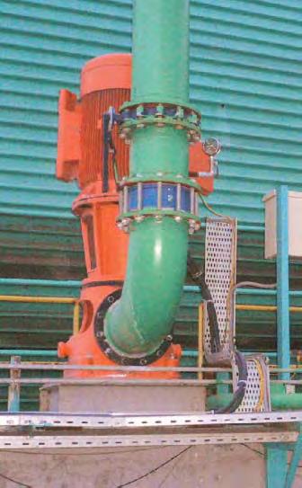

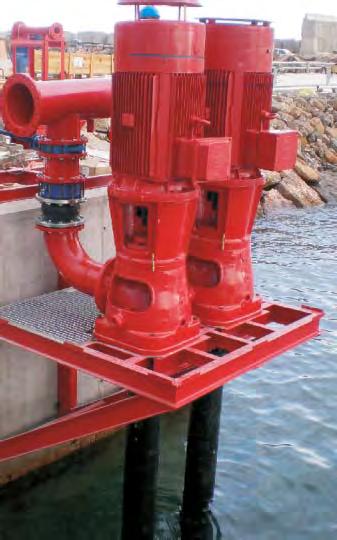
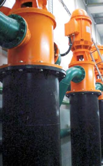
403
404
405
406
407
408 QUALITY OF MACHINERY TU R TURKISH QUM

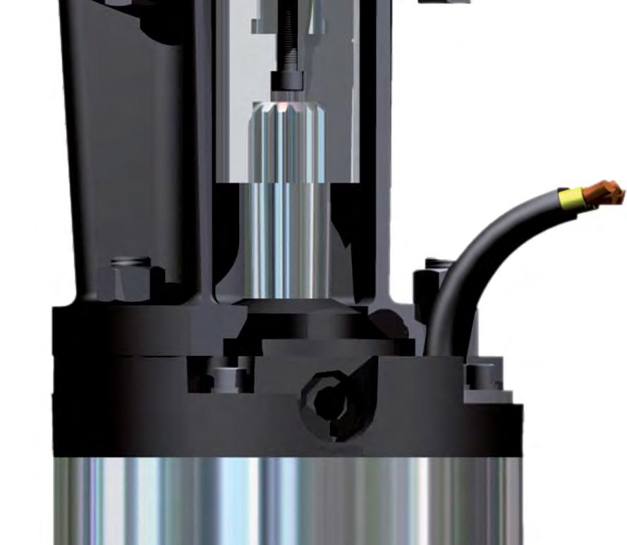
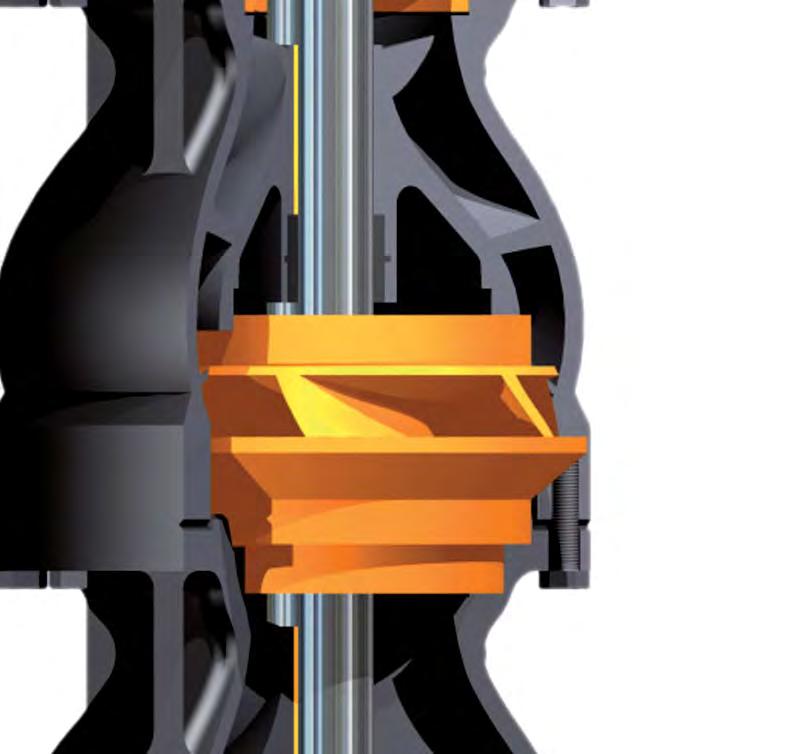
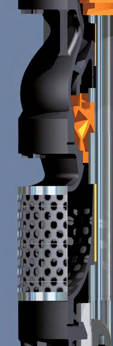


409

410


411
412

413
414
415
416
417
418

419

420 QUALITY OF MACHINERY TU R TURKISH QUM