APPLICATION OF UNDERWATER ACOUSTIC REMOTE SENSING DAM AND IMPOUNDMENT SYSTEM EXAMINATION CASE STUDY EXAMPLES. Kenneth J. LaBry
|
|
|
- Annis Norman
- 5 years ago
- Views:
Transcription


1 APPLICATION OF UNDERWATER ACOUSTIC REMOTE SENSING DAM AND IMPOUNDMENT SYSTEM EXAMINATION CASE STUDY EXAMPLES Kenneth J. LaBry The advanced age of the Dam infrastructure in the United States and the general lack of attention that this infrastructure has received since beginning operation is requiring a comprehensive examination to provide information for evaluation of critical needs and to develop monitoring plans in order to acquire the analytical information for predictive maintenance. The following discussion relates the integrated process used for applying underwater remote sensing techniques and technology to the examination of submerged components of aging dam systems. Case Study 1 Bayou D Arbonne Dam Near Farmerville, LA Fenstermaker, as team lead, was tasked with performing a comprehensive examination and inspection of the dam utilizing innovative technology in underwater acoustic imaging and

2 profiling. To bring an added level of visualization and uniqueness to the project, Fenstermaker combined the data from High Definition Laser Scanning of the superstructure and surrounding land mass environment with the acoustically scanned substructure and water bottom. This resulted in a unique and comprehensive three-dimensional model of the dam system, including water bottom erosion patterns. Key observations during the course of this project were a water flow transiting through the dam spillway structure, indicated by the existence of two small holes in the sediment at the interface of the water bottom and the heel of the dam, and a corresponding high velocity water stream exiting near the lower dispersion blocks downstream and in alignment with the holes in the sediment. Detection of washout holes at the toe of the upstream slabs.


3 Washout holes and correlated high velocity water discharge downstream, from dispersion blocks on the spillway apron. Another key observation was the convoluted erosion pattern which indicated the water flow path over the spillway and through the sluice gates discharging downstream. The channelization had evolved into a deviation far from the design and was threatening the backside of the southern embankment.
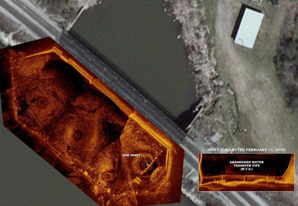
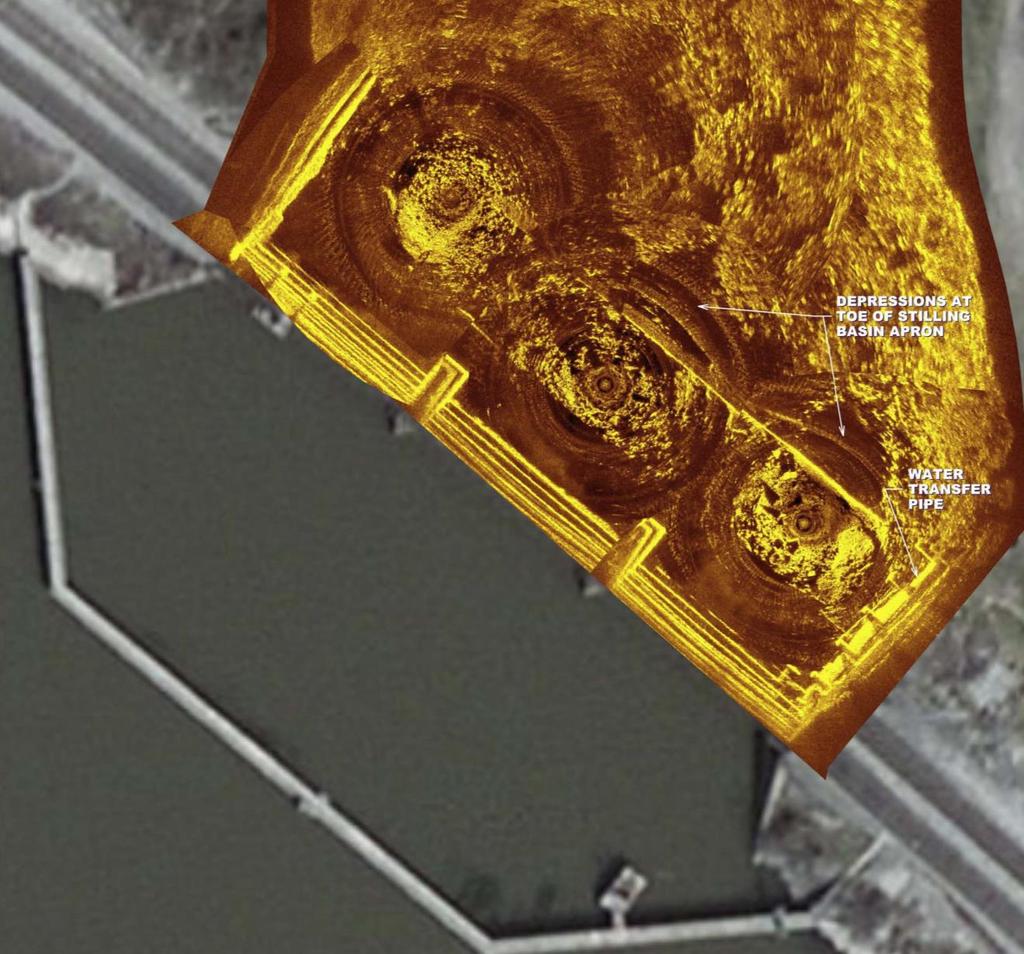
4 Three dimensional composite model of the as-found condition of the D Arbonne Dam and surrounding dam system environment Both of these significant observations provided the owner the information to develop a targeted plan of action for maintenance rehabilitation of the structure. Utilizing underwater acoustic imaging and underwater acoustic profiling in conjunction allows for the qualification and quantification of structural and water bottom abnormalities in a costeffective manner. The production rate of area covered relative to other methods provides a significant cost savings as well as providing a much more extensive and non-subjective data set that can be used for subsequent comparative analysis with future surveys performed in the same manner. The geo-referencing of all acoustic data affords real world displacement measurement along the water bottom and structural surfaces. Case Study 2 Fenstermaker was tasked with performing a comprehensive Underwater Acoustic Imaging examination of Cross Lake Dam, a 100-year-old Dam whose spillway resides beneath a major railroad bridge and also comprises the bridge support substructure. The Dam spillway system contains an abandoned water intake. The lake is the primary water supply for the City of Shreveport, LA. A multi-beam Echosounding study of the entire length of the Dam embankment was also performed in order to map the water bottom surface where the earthen embankment meets the lake bottom. The UAI imagery showed a degrading concrete surface with exposed aggregate throughout the submerged components of the structure, and instances of shallow voids as is typical of aging concrete structures. Also observed was the abandoned steel water transfer pipe penetrating through the concrete spillway, and the adjacent decommissioned pipe which is terminated near the spillway structure on both sides. An inspection of the submerged components of the active water intake approximately one mile from the spillway was also performed, showing debris accumulation and light damage to the intake grates.
5

6