Development of the STORASOL -HTTESS- storage technology
|
|
|
- Darleen Barker
- 5 years ago
- Views:
Transcription

1 Development of the STORASOL -HTTESS- storage technology 1

2 1. High temperature storage systems 2. STORASOL High temperature thermal energy storage 3. Development 4. FAQ (Frequently asked Questions) 2
3 1. High temperature storage systems 2. STORASOL High temperature thermal energy storage 3. Development 4. FAQ (Frequently asked Questions) 3
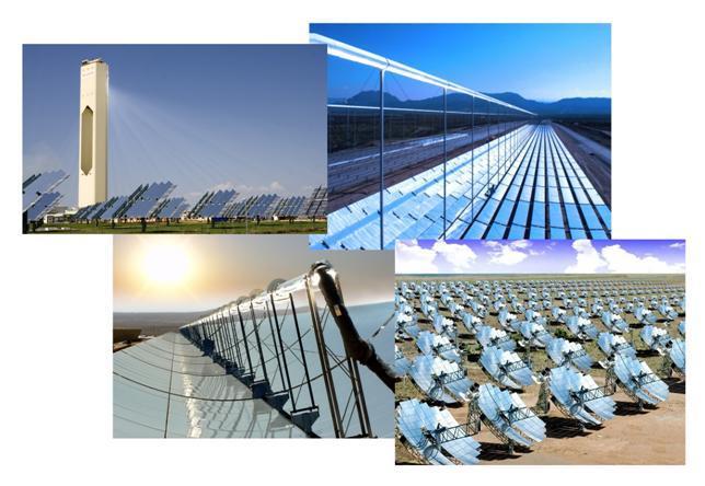
4 1. High temperature storage systems Classification of Thermal Energy Storage Systems (TESS) low temperature approx. < 220 C TESS high temperature approx. > 220 C Following pages show recently developments in storage technology regarding thermal storage systems. water/steam rock etc. Not considered in the following report! short term storages long term storages water/steam storage ceramik Molten salt STORASOL storage (air, rock, sand, ceramik) PCM 4 concrete

5 1. High temperature storage systems Molten salt storage system Molten salt storage of the Andasol Solar-plant in Spain (parabolic trough CSP plant) Molten salt storage systems are currently the only commercially available technology for high temperature. Solar salt is used as Heat storage material up to a temperature of approx. 580 C. The useful temperature range is bounded to approx. 280 C (sufficient distance to solidification temperature range of C). 5

6 1. High temperature storage systems Water/Steam storage (Ruth s storage) Ruth s storage of the PS10 solar tower. When fully charged, the operation will be prolonged by about 1h. Cons: steam accumulator can roll off during discharging only saturated steam, not superheated steam; expensive and therefore not suitable for larger storage capacities. 6

; operational")
7 1. High temperature storage systems PCM storage (Phase Change Material) PCM storage system have a high energy density and cover the area of the evaporation / condensation during charging and discharging very good. Cons: Expensive; limited operating temperatures (depends on choice of material); operational challenges. PCM demonstration plant (DLR, Litoral of Endesa in Carboneras, Spain) 7


8 1. High temperature storage systems Concrete storage system The heat is transferred to the concrete via tubes and the flowing heat transfer medium. In discharging mode the heat is transferred from the hot concrete to the water/steam cycle again. Cons: High pressure losses due to many long lines; Expensive; Concrete must be free from water before use. 8
.")

9 1. High temperature storage systems Ceramic storage Storage consist of ceramic elements which are integrated in a steel tank. The elements are porous, ceramic bricks (Ceramic is a good heat storage medium). Trough these bricks hot air is blown for the intermediate storage of the heat. This technology with the arrangement in the tower basically works as a short-term storage. Cons: operational difficulties in the interaction of the closed air system, the receiver and the heat exchanger; expensive. Solar Tower Jülich, Germany 9
10 1. Hochtemperatur - Speichersysteme STORASOL - HTTESS, developed by enolcon gmbh Hot air is used in an open loop with recuperation heat exchanger as a heat transfer medium. The heat storage medium is gravel, sand, pieces of rock, etc.. The whole system is simple, robust and very cost effective. The possible disadvantage of a higher auxiliary consumption is eliminated by the innovative arrangement of the rock layers, resulting in a lower pressure drop. 10
11 1. High temperature storage systems Overview of the different technologies: Technology Commercial scale Small scale Demoplant Research and development Spez. invest. costs Economical potential for base load applications Molten salt storage + o Ruth s storage PCM storage o + Concrete storage o + Ceramic storage ( ) Sand/Rock storage Thermo-chemical storage o + Fluidized bed storage + + Not mentioned here: enolcon-/storasol - molten metal storage. First prefeasibility studies and patent development has been performed. 11
12 1. High temperature storage systems 2. STORASOL High temperature thermal energy storage 3. Development 4. FAQ (Frequently asked Questions) 12

13 On the basis of market and technology observations of the last few years, combined with the long-term experiences of enolcon`s key people as EPC-contractors and operators of power plants, enolcon has started to look for a thermal storage system which can fulfil the following premises: Economics: Reduction of CSP-electricity price, acceptable costs for other applications Simplicity: Keeping share of innovative new technology low, application of proven components and equipment Time: Commercially available within max. 3 4 years Integration into a consistent HTTESSconcept Fit for Future: No restriction with regard to application for developing technologies (e.g. CSP-Technologies to higher steam temperatures and pressures) Adaptation: Applications possible independent from CSP-technology. Possible use for other applications as well (e.g. pressurized air power plant) Robustness: Easy operation with regard to countries with low level skills and challenging environments 13
14 Functional concept of the HTTESS for CSP-Application/ Overcapacity-Heat: 1. Charging mode Heat storage with storage material Ambient Ambient Air-Airheat exchanger Charging heat exchanger Cooler Fan Condensate to solar field Steam from solar field Ambient Recovery heat exchanger Condenser Preheater evaporator + superheater Feed water Steam to turbine 14
15 Functional concept of the HTTESS for CSP-Application/ Overcapacity-Heat: 2. Discharging mode Heat storage with storage material Ambient Ambient Air-Airheat exchanger Charging heat exchanger Cooler Fan Ambient Condensate to solar field Recovery heat exchanger Condenser Preheater Steam from solar field Optional: Additional firing with Bio- or natural gas evaporator + superheater Feed water Steam to turbine 15
: 1.")

16 Functional concept for the HTTESS for industrial applications (Tertiary/secondary control energy/ excess power): 1. Charging mode Heat storage with storage material Ambient Transmission grid Ambient Air-Air heat exchanger Electrical air heater Fan Ambient Recovery heat exchanger Feed water Steam to turbine or process 16
17 Functional concept for the HTTESS for industrial applications (Tertiary/secondary control energy/ excess power): 2. Discharging mode Ambient Transmission grid Heat storage with storage material Ambient Air-Air heat exchanger Electrical air heater Fan Optional: Additional firing with Bio- or natural gas Ambient Recovery heat exchanger Feed water Steam to turbine or process 17

18 Overview of the functional concept for charging and discharging mode: 18

19 The overall system is based on the STORASOL -thermal storage technology developed by enolcon consists of: - Fan 2. STORASOL High temperature thermal energy storage - air duct + flaps - Heat exchanger - Recovery heat exchanger - Thermal storage and storage material The thermal storage including storage material and the setup of the overall system is a new development, all other components are state-of-the-art. The overall system and the constructional details of the storage vessel are registered to worldwide Patent approval (PCT/EP2011/063453). A following registering to patent approval is concerning a superheater-storage system based on molten metal as heat storage material. 19
20 The enolcon-httess-technology is essentially quite simple. However, during detailed design, several different interconnecting and influencing factors need to be considered. Pressure loss Storage - geometry Storage material Temperature (fluid & particle) Superficial velocity Particle diameter Heat conductivity Height of fixed bed Temperature conductivity Airflow surface Aux. consumpti on Porosity (fixed bed & particles) Storage Capacity 20


21 Enolcon has developed several calculation tools for the design of various applications for High temperature heat storage systems (e.g. calculation methods based on the VDI Wärmeatlas, results and experiences from own demonstration and pilot plants are taken into consideration) 21

22 Example for a calculated temperature curve over time during charging of the storage: 22

23 Example for a calculated temperature curve over time during discharging of the storage: 23
24 Test system TESS001: Construction of a test system in order to confirm calculations and to derive design parameters for next level demonstration plant. Commissioning in octobre 2010, in operation until octobre 2011 Set-up of test system TESS001: 1: side channel blower 2: air heater 3: pitot tube with temperature compensation 4: air channel 5: Valve 6: Thermocouple 7: Pressure sensors 8: Reactor 9: control cabinet 24


25 Main focus of the investigation was:: different storage materials pressure losses reproducibility. TESS001 is capable of different flow directions for charging and discharging operation Heater on Heater off TESS001 before comissioning: charging discharging Test system partly insulated Control cabinet gravel 8/16 as possible storage media: 25
26 Comparison of calculated results with measurements: Dependency of specific pressure loss according to superficial fluid velocity (120 cm reactor-filling) The messurement data fits very well according to the results of the different calculated models! 26

27 The third measurement shows expected results: Temperature of storage material at ~ 400 C Temperature profile in the first 20 cm Temperature profile at 40 cm and 60 cm 27
28 Comparison between calculated model and measurements of test system TESS001: The material specific characteristics were considered in the calculations The average superficial velocity and the inlet temperatures of the reactor for the relevant measurement time range have been considered in the calculations. The influence of the additional thermal heat capacity of the steel structure has not been considered yet. Graphs of the simulations are blue colored. Graph of the Measurements are shown in red/yellow colors. 28
29 Comparison of measurement and calculation in charging operation According model calculation (blue) measurement (red) Measurements fit very well according to the simulated curves! 29


30 2. STORASOL High temperature thermal energy storage Reproducibility of measurements is excellent (Temperature and pressure losses): Comparison of experiments: V & V & V
31 Conclusions derived from TESS 001 operation: a) The measurements give evidence, that the enolcon HTTESS-Concept will work properly. b) The measurements verify the calculations c) There is still a considerable impact by the steel structure that cannot be distinguished easily. d) The characteristic of the curves show a good heat transfer into the chosen storage media. e) The critical parameter pressure loss stays within the expected frame.. f) The measurement values show a very high reproducibility. g) The parameters like heat capacity and heat conductivity can only be very roughly quantified with this test system. 31
 Application in CSP-plants based on direct steam")
 Application as heat storage for superheating in a CSP plant Darstellung der Wärmemenge Q 1 während der Kondensation und Q 2 während der Abkühlung für das Beispiel mit 450 C und 100 bar: d)")
32 Studies and concept analyses: A huge number of studies have been executed in order to evaluate the enolcon- /STORASOL -HTTESS-concept in combination with different applications and tasks. These studies have been executed based on internal research projects as well as on behalf of a power utility and power plant equipment suppliers: a) Application in CSP-plants based on direct steam generation At 100 bar, 450 C: Q 1 /Q bar Q 1 30 bar Q C 330 C 235 C b) Application in CSP-plants based on heat transfer fluids. c) Application as heat storage for superheating in a CSP plant Darstellung der Wärmemenge Q 1 während der Kondensation und Q 2 während der Abkühlung für das Beispiel mit 450 C und 100 bar: d) Application as storage for wind power e) Application as high-temperature heat storage for compressed air energy storage f) Application as heat storage within coal or gas fired plants g) Application as energy storage replacing oil-fired auxiliary boilers. h).. Due to the low investment and mantainacne costes there are a lot of possible applications for the STORASOL -HTTES-Systems. 32
 33")
33 Basic structural design of one large scale module (closed) 33
34 Basic structural design of one large scale module (cutting): 34

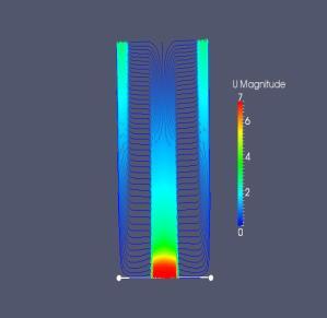
35 Basic air flow for one large scale module (cutting): By creating a huge surface, the air flow speed could be reduced and therfore the pressure loss over the whole system is minimized. 35

:")


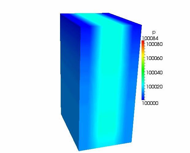
36 2. STORASOL Hochtemperatur - Wärmespeicher Computational fluid dynamics (CFD): optimization of the geometry reduction of the pressure loss, etc. construction of a air flow rig in parallel verification of the CFD-simulations experimental analysis of the air flow etc. 36
37 Basic constructive design of the interconnection of several modules in large scale (closed) The covered area of the enolcon-/storasol -HTTESS-Technology is less compared to other storage systems (e.g. molten salt storage). Due to the modular design, the STORASOL -HTTESS-Technology is very flexible and can be adapted to the special needs of the layout of a large scale plant. 37

38 3D-Desgin of a possible super heater-httess-system; conceptual design with two air exhaust vents. Covered area: ca. 15 x 18 m, approx. height: 5-6 m. Storage module Air-Air heat exchanger Charging and discharging heat exchanger air fan 38


39 Based on the individual needs of the project, the design of the system is adapeted and optimized. Besides a variety of parameter the design is influenced for example by the necessary charging and decharging time interval. 39


40 First small scale demonstration plant of the overall STORASOL -HTTESS-system: At the moment, enolcon is operating a small scale demonstration plant of the HTTESS-system inducing all relevant components. With experimental results on real operational temperatures the applicability and functionality of the system is demonstrated and analyzed. The system contains:: - air fan - Air/Air-heat exchanger - two HTTESS-module in small scale - fittings - measuring device This small scale HTTESS-demonstration plant has a thermal storage capacity of about ca. 10 and 25 kwh,th on a temperature level of up to 550 C. Based on the experienced with this demonstration plant, the design of the large scale demonstration plant is optimized and first operational experiences are made. The commissioning was done in April 2013, first cycles where already successfully made. Meanwhile a lot of know-how and experience has been gained and with the TESS002 B dedicated items to improve the large scale construction are in the focus. 40


41 Engineering, construction and operation of a demonstration plant, where the main parameters and design values will be realised in large scale dimensions (M 1:5 to 1:1). Start of this project was end of year STORASOL will finance the works. The engineering works and the project management will be executed by enolcon. Target of this project is the realisation and the operation of a HTTESS-storage in the capacity level of approx. several 100 kwh th. Key elements of this demostration plant will be the following parameter: High reliability and life time in using proven system components of the conventional energy- and power plant technology Use of storage material with an economical energy density Demonstration as long term storage for temperatures in the range of 400 C to 600 C Operational tests and evaluation of an optimal technical configuration during test operation, the results will be used as basis for later commercial application. Dedication of scale-up parameters for a capacity of up to 100 MWh,th or bigger, allowing large scale commercial application. Optimal Integration in a power plant cycle. Simple and robust construction. 41
42 1. High temperature storage systems 2. STORASOL High temperature thermal energy storage 3. Development 4. FAQ (Frequently asked Questions) 42


43 3. Development Summary of the technical development of the enolcon/storasol - HTTES-System: approx engineering-hours (more than 4,5 man-years) development (techn. calculations, planning, pilot- and demonstration plants, experiments, studies, etc. etc.) several studies for energy utilites and industrial projects construction and operation of a HTTESS-pilot plants construction and operation of an air flow rig construction and operation of a small scale demonstration plant of the overall HTTES-system design for CSP-plant applications computational fluid dynamic simulations several patents registered launch of the STORASOL GmbH operation of TESS002 and TESS002 B design, construction and operation of a large scale demonstration plant starting end of year 2014 (TESS003) 43

44 3. Development Strategic considerations on storage use - experimental works on pilot plant - technical optimization - Fluid dynamics: first simulations - Development and anlysis of possible applications (CAES, Wind, ind. heat, etc.) - market assessment - economical assessment - Experimental works on flow test rig - Construction and experimental works on a first small scale demonstration plant - Optimization on fluid dynamics and whole system - launch STORASOL GmbH - Further development and optimization of the system - Marketing and sales - Construction of the first commercial HTTESS-system Enolcon CSP activity since market- / technology analysis on storage systems (HTTESS) - first enolcon conzept - start development enolcon HTTESS - Engineering/Studies - Patent / Registration - Pilot plant planing, construction - investigation CAES - further simulation concerning fluid dynamics - Cost estimation full scale storage - Construction flow test rig - Construction and experimental works on HTTESS-test rigs - further optimization of the construction - Construction of a first large scale demonstration plant of the HTTESS system 44


 Application: Wind")
45 3. Next steps, further development Enolcon CSP activity since Future Application: adiabatic compressed air energy storage Application: industrial heat and steam generation Future HTTESS-Demonstrator, on going development Application in CSP plants (technology independent) Application: Wind power storage 45
46 1. High temperature storage systems 2. STORASOL High temperature thermal energy storage 3. Development 4. FAQ (Frequently asked Questions) 46
47 4. FAQ (Frequently asked Questions) Following, some frequently asked questions concerning the technology are listed: Question: Answer: What are the reasons for the widely reduced investment costs of the The main difference regarding the investment costs compared to other STORASOL-HTTESS compared to molten salt or battery storage system? energy storage systems is the much cheaper storage material rock/gravel (approx /t compared to e.g. solar salt approx /t). An additional point is the wide use of standard components that can be bought under market conditions (Heat exchangers, fans, storage vessel, etc.). Therefore STORASOL is able to follow a multisourcing strategy reducing costs for the main components. What is the reason for the low operational costs of the STORASOL-HTTESS? The operational costs for the storage systems are mainly depending on the electricity demand of the fan. Based on the innovative arrangement of the storage material (Increasing of the surface area ==>decreasing of the necessary air velocity==>exponential decreasing of the pressure loss) the power consumption of the fan (and therefore the electricity demand) is To what extent the maintenance costs for the STORASOL-HTTESS are to be? The use of relative simple standard components is resulting in low maintenance costs. Based on our experience these costs can be estimated in a range of % of the investment cost of the overall HTTES-system 47
48 4. FAQ (Frequently asked Questions) Question: Answer: What is the reason for the low pressure loss over the rockbed with about 5- This is mainly based on the fact that the air flow after entering the module 15 mbar? flows onto a large surface and is thereby slowed down (from approx m/s to 0,5-1,5 m/s). The relation between pressure drop and flow rate is exponential, resulting in a significantly above average increase of the pressure loss higher speeds. Furthermore, only single modules are charged. The optimization of the flows within the modules as well as the structural design constitutes an essential feature of the STORASOL-system. What is the reason for the use of air in an open cylce instead of using a closed system? What is the role of the Air-/Air-heat exchanger? The use of an open system is based on thermodynamic and practical reasons: cold air from the ambient needs less energy for transport than hot air. Within a closed system additional coolers are necessary in order to handle the charging and discharging mode. (higher investment costs, complex operation). From practical reasons, it is easier to operate a fan with a cold air flow and therefore low temperatures. With the air-/air-heat exchanger the efficiency of the overall HTTES-System is increased by exchanging the not used heat with the incoming air flow. Therefore an optimal utilisation of the available heat is achieved. 48
49 4. FAQ (Frequently asked Questions) Question: Which range of temperature could be achieved by the STORASOL-HTTESS? Why is the STORASOL-HTTESS system not yet available in large scale on the market? Answer: In principal the STORASOL-HTTESS can cover a temperature range of approx C with the current setup (compared to molten salt and solar tower: approx C, molten salt and parabolic trough approx C). Regarding the storage material, the possible temperature range could be extended to temperatures above 1100 C. Recent projects with a high investment volume of more than 100 Mio, including a commercial scale high-temperature storage system, are usually financed by banks. High scale project financing by banks is only possible for projects using exclusively state-of-the-art technology. To reach this status, the construction and successful operation of a demonstration plant is required. With additional positive due-diligence of the technologies (regarding technical functionality and operational capability) it is possible to finance, build and operate the technology in a commercial scale. The STORASOL system is at the moment in the planning phase of such demonstration plant. 49
50 Thank you for your attention! STORASOL GmbH Pleidelsheimer Straße 47 A Bietigheim-Bissingen Tel.: +49 (0)