M/s Malur Effluent Treatment Plant., Malur, Kolar Karnataka
|
|
|
- Penelope Baldwin
- 5 years ago
- Views:
Transcription
1 M/s Malur Effluent Treatment Plant., Malur, Kolar Karnataka South Zonal Office, Bangalore 1 Name/ address of CETP/ company: M/s Malur CETP, Malur Industrial Estate, Malur Kolar, Karnataka 2 Area occupied by CETP (plot area): 6.6 acres (3acres built-up area, 3.6 acresgreen belt) 3 Total no. of staff (including operational & skilled persons): 30 employees (3 shifts/day, 4 operators/ shift) 4 Contact person (Name, Designation, and Contact No, FAX, e mail): 5 Status of CETP: operational or closed (if closed since when): 6 Consent & Authorization: Valid up to: Applied (date of application): 7 Industrial area/estate (s) connected to CETP: Mr. G.V. Gore, Managing Director Cell no , Fax no cetpmalur@gmail.com Partly-Operational The consent under Water and Air Act is valid till The Hazardous waste authorization is valid till KIADB Industrial Area Malur KIADB Industrial Area Narasapur KIADB Doddaballapur KIADB Industrial Area Jigani 8 Type of industries in the connected industrial areas: CETP is receiving effluent from textile processing, food processing waste, pharmaceutical intermediate w/w, Engineering companies. Industrial area/estate Type of industries Number of industries KIADB Industrial Area Malur Food Processing 5 KIADB Industrial Area Automobile engineering 9 Narasapur KIADB Doddaballapur Pharmaceuticals 7
2 KIADB Industrial Area Jigani Pharmaceuticals Number of member industries of CETP: 9 Method of collection of effluent (pipeline/tanker): If collection is by tankers, average No. of tankers/day: Capacity of tankers, m 3 : 10 Details of flow meters (Type, location and operational status): 11 Treatment capacity: MLD / Design flow of CETP: m 3 /hr 12 Wastewater treated: MLD / Average flow reaching CETP m 3 /hr 13 Wastewater if bypassed in CETP from treatment: Flow/volume of wastewater bypassing treatment units in CETP: 14 Treatment units and dimensions (Attach flow chart also): 15 Details of chemicals used: 25 The CETP has 9 tankers. 10,000 liters capacity and 2 tankers of 6,000 L capacity for collection of wastewater 9 tankers/day 9 tankers of 10,000 liters capacity and 2 tankers of 6,000 L capacity The unit has not installed flow meter at the inlet and outlet of CETP. Installed- 140 KLD Actual- 90 KLD No by pass arrangments Enclosed at Annexure - 4 No. Name of chemical Quantity, kg/month 1 Alum Ferrous sulphate Polyelectrolyte 50 4 Caustic Soda 500
3 16 Design parameters & monitoring results (based on composite sample for 08 hours): *All values are in mg/l, except ph Low TDS Stream : Parameters Designed inlet norms SPCB inlet norms Raw effluent after equalization Final outlet Discharge limits (Standards ) ph SS TDS Conductivity BOD COD O & G Nil 10 NH 3-N TKN Phenol Nil - BOD/COD 1: :3.8 - Ratio Cyanide Nil MLSS in mg/l MLVSS in mg/l DO in mg/l SBR High TDS Stream: Parameters Designed inlet norms SPCB inlet norms Raw effluent after equalization Final outlet Discharge limits (Standards ) ph Neutral SS TDS Conductivity BOD >20 - COD O & G ND 10 NH 3-N ND 50 TKN Phenol BOD/COD Ratio Cyanide
4 17 Primary sludge management system: Primary sludge generation rate (m 3 /day or tons/day): Number & capacity of sludge drying beds: Details of any other methods for sludge thickening (filter press/rotary filters etc.) Quantity of sludge stored: Primary sludge disposal- *(Secured landfill or TSDF): *(Co-incineration if any): About 3-4 MT/Annum 02 No. SDB No Sludge is packed in polythene bags and stored in the unit premises and reported that sludge is being disposed to TSDF, Ramky. 18 Excess Biological Sludge Management System: Excess Biological Sludge generation rate: Number and capacity of sludge drying beds: Details of any other methods for sludge thickening (filter press/rotary filters etc.) Quantity of sludge stored: Excess Biological Sludge Disposal: NA 19 Conveyance system for disposal of treated wastewater: Drains/ Pipeline Pipe line with sprinkler 20 Method of Treated wastewater disposal: River/ Land/ Marine/ Others (Specify) Part of the treated effluent is discharged on land for irrigation while part of the effluent after filtration at GAF is used by the workers for domestic purposes. 21 Reject Managment Multiple Effect Evaporator is installed to treat High TDS Effluent 21 Capital cost with breakup of sources of Rs. 4.3 Crores funds: 22 Operational cost: Rs. 30 lakhs/month
5 23 Date of Inspection May 3, Inspected by (Name & Designation): Mrs. H.D. Varalaxmi, EE Mrs. Mahima T, AEE 25 OBSERVATIONS & FINDINGS 1. M/s Malur CETP (unit) formerly known as M/s Eco Engineering Malur is situated at Malur Industrial Estate, Kolar. Reportedly, the unit is treating 90 KLD of effluent against the design capacity of 140 KLD. 2. The unit has 25 member industries from different industrial estates located at Malur, Jigani, Bommasandra, Yelahanka and Doddaballapur. Though unit is located at Malur Industrial Estate, only four industries from Malur Industriasl Estate are sending effluents to this unit. 3. The unit has 9 tankers of 10KL capacity and 2 tankers of 6KL capacity. 4. The unit has not provided any flow meters or flow measuring devices at inlet and outlet of CETP and hence quantity of effluent treated and reused was not available 5. There was no proper conveyance system for conveying sludge from treatment units to sludge drying beds. 6. The unit has two separate treatment system for treatment of high TDS and Low TDS effluent. The unit receives about KLD of HTDS and KLD of Low TDS effluent. Effluent having TDS in the range of mg/l is considered as HTDS while TDS below 1000mg/l is considered as LTDS. On the day of inspection only biodegradable treatment system was in operational. 7. On the day of inspection HTDS treatment system was not operational and the outer wall of MEE and boiler were rusted. Settling tank and sludge drying beds were filled with HTDS effluent. Reportedly, the capacity of HTDS raw effluent storage tank is 120KL. High TDS treatment System: 8. The high TDS effluent after screening is treated in Settling tank by the addition of alum. Supernatant from settling tank after adjusting ph to 7 is evaporated in a 3 stage MEE of 30 KL capacity. The reported Feed rate in MEE is l/hr and MEE is operated for 4-5 days/ week.
6 9. The unit has three boilers (two boilers each of 14,000kg/hr and 8000kg/hr operating on bio-fuel and one boiler of 8000 kg/hr operated on diesel) to produce steam for MEE. 10. MEE condensate is being reused in the boiler. Semi-concentrate is separated into sludge and wastewater in the centrifuge, the supernatant from centrifuge being treated along with low TDS effluent while sludge is being sent to SDB. MEE concentrate is dried in SDB and disposed at Ramky TSDF. Low TDS effluent treatment system: 11. The unit has provided Cooling tower to reduce the temperature for effective treatment in SBR but however it was not operational. 12. Low TDS effluent after screening in both bar screens and fine screens is allowed to settle in a settling tank by the addition of alum. Supernatant from settling tank is treated in Sequential Batch Reactors (SBR). Part of treated effluent is used onland for irrigation within unit premises and part of effluent after treating through sand filter and activated carbon filter is used by workers for domestic purposes. Sludge from settling tank and SBR after drying is disposed to TSDF. 13. Completely dried and semi-solid Sludge generated from the unit is packed in polythene bags and stored in the shed. The shed is not properly floored there is possibility of leaching of hazardous waste into the ground. 14. The unit is equipped with a laboratory within its premises but however no analysis results were available 15. Centrifuge has worn out and was not in operation. 16. Grab samples were collected from HTDS collection tank, HTDS concentrate and SBR and results are as follows: S.No. Parameter High TDS Collectio n tank MEE Concente ration tank Low TDS collection tank Collectio n tank no. 1 Collection tank no. 2 Final Treated Effluent 1 ph EC (µs/cm TSS (mg/l) TDS (mg/l)
7 5 BOD (mg/l) COD (mg/l) Sulphate (mg/l) _ Copper (mg/l) Cadmium (mg/l) Chromium (mg/l) BDL BDL BDL BDL BDL 11 Iron (mg/l) Manganese (mg/l) Nickel (mg/l) Lead (mg/l) BDL BDL BDL BDL BDL 15 Zinc (mg/l) Cobalt (mg/l) Parameter Aeration tank MLSS (mg/l) It is informed that Karnataka State Pollution control Board has not given any concentration limit for receiving effluent from member units From the above result, the treated effluent using for irrigation/plantation was not meeting the standards w,r,t TDS. The MLSS concentration (195 mg/l) in aeration tank also found very less whcich indicates the poor operation. The solid concentration of MEE concentrate (2.5%) stored indicates the poor operation of MEE, the solid concentration was found increased from 1.8 % to 2.5 % which indicates the in adequate treatment system to handle High TDS Effluent. 30 Recommendations w. r. t. specific observations made during inspection: 1. The CETP shall be directed to operate the unit properly and efficiently to achieve the desired standards. 2. The CETP shall be directed to achieve zero discharge by installing tertiary treatment system for Low TDS effluent. 3. The CETP shall be directed to monitor ground water quality of the surrounding area and to submit reports to CPCB/SPCB. 4. Present practice of concentration of High TDS effluent in Multi effect evaporator and separation of solids in centrifuge found inadequate. Hence the CETP shall be directed to install adequate stage of MEE and drier or salt recovery system for efficient treatment of High TDS effluent and to achieve
8 zero discharge. 5. The CETP shall be directed to install electromagnetic flow meter at the MEE feed, MEE condensate, Concentrate and the steam feed. 6. The unit shall be directed to appoint qualified and skilled operator to operate CETP. 7. CETP is receiving effluent from very furthest point, hence KSPCB may be directed to devise a policy so that industries may send their effluent to the nearest CETP. Mahima T. Scientist B H.D. Varalaxmi Scientist C A. Manoharan Zonal Officer


9 Photographs of M/s Malur CETP Fig 1: Process flow diagram of Malur CETP Fig 2: High TDS raw effluent storage tank


10 Fig. 3- High TDS Settling tank tank Fig 4: Conveyance of HighTDS effluent from storage tank to concentrate storage tank Fig 5: MEE Fig 6: MEE concentrate storage tank


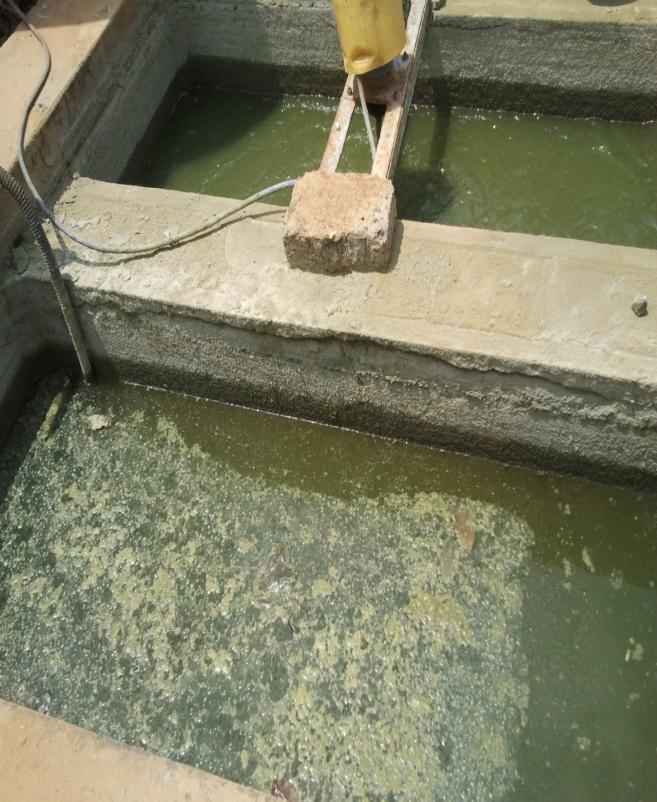
11 Fig 7: Low TDS effluent storage tank Fig 8: Low TDS effluent Fig. 9 - Low TDS effluent Settling tanks
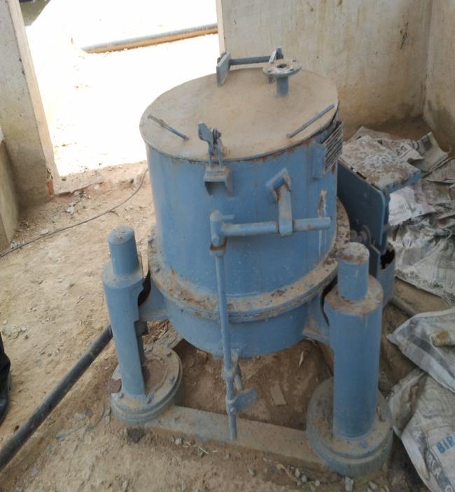
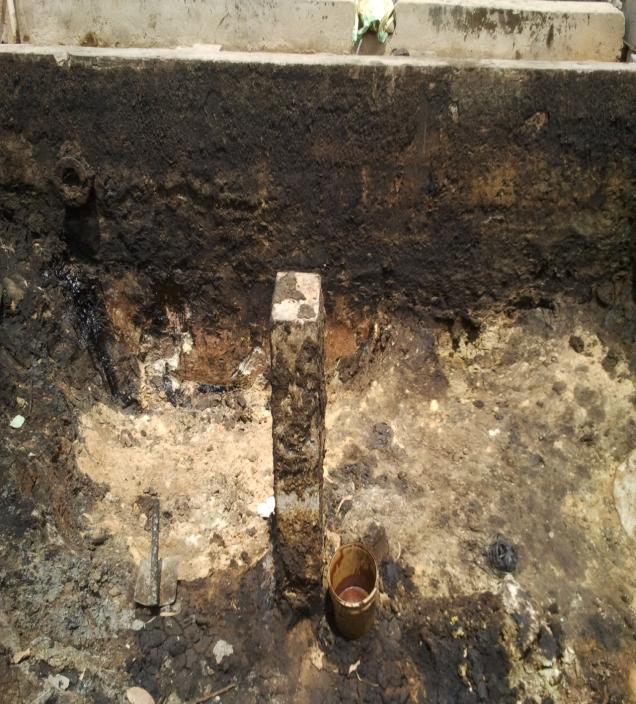
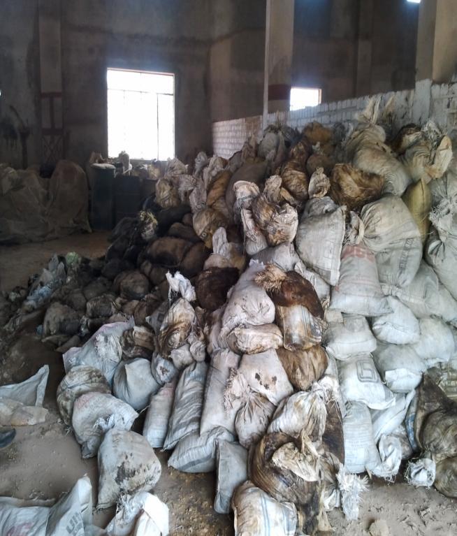
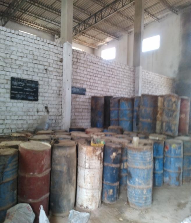
12 Fig 10: Centrifuge Fig 11: Sludge drying bed Fig 12 : Sludge storage shed
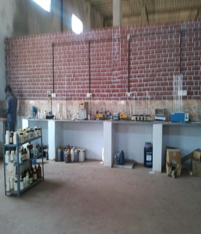
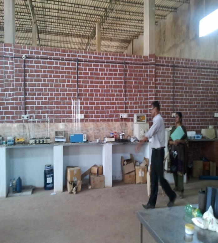
13 Fig 13: Laboratory
14 No. F. Tech/87/CETP-KA/ZOB/ / June 28, 2013 To The Member Secretary, Central Pollution Control Board, Parivesh Bhawan, East Arjun Nagar, Delhi Sub: Performance Evaluation report of M/s Malur Effluent Treatment Plant., Malur, Kolar,Karnataka - regarding. Sir, With reference to above, a performance evaluation report of Common Effluent Treatment Plant (CETP s) at M/s Malur Effluent Treatment Plant., Malur, Kolar, Karnataka was carried out on May 03, The inspection report of the above mentioned CETP is submitted for your kind perusal and further action please Encl : As above Yours faithfully, (A. Manoharan) I./c Zonal Office
15