Development of Post Combustion Capture Technology
|
|
|
- Marion Farmer
- 5 years ago
- Views:
Transcription

1 Development of Post Combustion Capture Technology IEAGHG 1 st Post Combustion Capture Conference, 17 th to 19 th 2011, Abu Dhabi May

2 Doosan Power Systems Vision To be a global leader in delivering advanced clean energy technologies, products and services. 1


3 Part of the Doosan Group Doosan Group Doosan Heavy Industries & Construction Casting and Forging Nuclear Doosan Power Systems Power Plant Construction Desalination Turnover Employees Doosan Group Doosan Heavy Industries & Construction Doosan Power Systems $15 Billion $1.3 Billion $5 Billion* 36,400 5,800* 6,000 *Figures exclusive of DPS data and correct to the end of the financial year for

4 Doosan Power Systems Organisation Doosan Group Doosan Heavy Industries & Construction Doosan Power Systems Boilers Doosan Babcock Turbines Škoda Power Plant Services Doosan Babcock Wind 3
5 Post Combustion Capture Leading Edge Technology

6 HTC Purenergy Overview HTC is the CO 2 Capture technology licensee of the University of Regina, who has specialised in Carbon Capture since HTC s Technology Centre is commercially aligned with Doosan, International Test Centre for CO 2 Capture, and the International Risk Assessment Centre Laboratories for solvent development, materials and process design. CO 2 enhanced oil recovery technical expertise commercialized through subsidiary EHR Enhanced Hydrocarbon Recovery Corp. Smaller scale modular capture systems for SAGD and Heavy Oil consolidated into Calgary based subsidiary HTC CO 2 System Corp. One stop for solvent development, process enhancement and plant Integration 5

7 Doosan Power Systems HTC Purenergy Our Goal To be recognised as the market leader in Post Combustion Carbon Capture technology and application, with proven product leadership to support the Core Power Island EPC product offering throughout the Doosan organisation. An Alliance Global licence agreement signed in 2008 between Doosan Power Systems and HTC Purenergy Technology transfer up to 30 engineers and specialists from Doosan Power Systems seconded to Regina, Saskatchewan. Future Development Doosan and HTC participate in collaborative research with the University of Regina which has some of the most comprehensive carbon capture research and development facilities in the world This enables the latest technological advancements to be provided to our Customers. 6
 High efficiency system Low degradation rates Tailored to meet operating and flue gas conditions Scale-up validated against actual operating data from several plants as large as 800 TPD (with")
 Operating conditions Proper application of numeric modeling tools Patents in place for high efficiency configured to advanced solvent Patents in place for steam side plant integration Optimised")
8 Technology Leaders Advanced Solvent designer (RS family) solvent providing: Low cost commercially available ingredients (~$2.60/kg) High efficiency system Low degradation rates Tailored to meet operating and flue gas conditions Scale-up validated against actual operating data from several plants as large as 800 TPD (with +/- 3% accuracy) Most importantly, scale-up is only achievable through a complete and thorough understanding of: All physical and chemical properties (kinetics, diffusivity, etc.) Operating conditions Proper application of numeric modeling tools Patents in place for high efficiency configured to advanced solvent Patents in place for steam side plant integration Optimised Process Design Heat Integration Reduction in Steam Advanced solvent, advanced process and optimised integration provide maximum customer value 7


9 Test Facilities and Demonstration Projects Facilities & Technology create a winning edge 20+ Years of Demo Industry Leading Scale ITC 1t/day Opened in 2003 Flue gas from natural gas combustion Includes equipment to study corrosion, material selection, solvent degradation and kinetics ERTF, 1t/day Commissioned in 2010 Ability to test wide range of coals and other fuels High degree of flexibility and accuracy to test wide range of Solvents and other modifications Boundary Dam, 4t/day Commissioned in 1987 Dedicated to post-combustion capture since 2000 Captures CO2 from flue gas emitted from lignite-fired boiler Upgraded in 2007 to evaluate advanced process with RS-2 Ferrybridge, 100 t/day Largest PCC demonstration plant in the UK Long-term testing and validation of process and solvent performance Evaluate transient conditions and process control Extensive monitoring planned Performance demonstrated on wide range of fuels and different plant configurations 8
10 Doosan Product Development and Commercialisation Process Technology Status and Scale-up


11 Doosan Power Systems Post Combustion Capture Projects Development Roadmap Target Slipstream 100t/d CO 2 5MW e Ferrybridge Large Demonstration Project (s) Slipstream ~3000t/d CO 2 150MW e Commercialisation Full Scale Plant 10,000t/d CO 2 500MW e 15,000 t/d CO MWe Emissions Reduction Test Facilities 1t/d to 5t/d CO 2 10

12 Demonstration Projects Emissions Reduction Test Facility Emissions Reduction Test Facility (ERTF) Upgrade for PCC Solvent Scrubbing A 160kW t combustion test facility at our R&D Centre in Renfrew, United Kingdom Capable of firing a very wide range of coals or natural gas. Originally constructed to test primary NO x reduction measures, subsequently adapted and upgraded to test secondary NO x reduction measures. Upgraded for oxyfuel operation as part of the OxyCoal-UK: Phase 1 project a collaborative project sponsored by the UK government with industrial and academic participation. 11
 4-off packed bed sections (with multiple solvent feed inlet points) Stripper column 8 NB (DN200) 4-off packed bed")

13 Demonstration Projects Emissions Reduction Test Facility ERTF Solvent Scrubbing Process - Equipment Absorber column 10 NB (DN250) 4-off packed bed sections (with multiple solvent feed inlet points) Stripper column 8 NB (DN200) 4-off packed bed sections Water Wash Column 8 NB (DN200) 1-off packed bed section Heat exchangers Gasketed (plate and frame) Pumps Duties met by triplex diaphragm pumps for high head low flow duties Variable speed drives for efficiency and ease of control 12


14 Boundary Dam Demonstration Plant Technology Demonstration Plant Operating since 1987 Donated to UoR in 2000 Upgraded 2007 Capture capabilities are 4 TPD Operating on lignite fuel Technology demonstration facility for client-specific parameters BDPS CO 2 Capture Plant Performance < 1.1kg steam/ 1 kg CO 2 captured which equates to less then 2.4 GJ/Ton CO 2 Total Capture System equates to ~110 MWe on an 800MWe Minimised impact to existing plant performance Industry leading plant efficiency 13
15 Main Test Campaigns at Boundary Dam CO 2 Capture Demonstration Plant Period Sep 2002 to Nov 2002 Jun 2003 to Aug 2003 Aug 2003 to Dec 2003 Feb 2004 to Aug 2004 Apr 2005 to May 2006 July 2007 to Nov 2007 Nov 2007 to May 2008 Oct 2009 to Apr 2010 Sep 2010 Test Objectives Establishing the baseline operation using MEA solvent Optimum operation & energy and utilities consumptions Operating at reduced reboiler pressure and temperature Optimum lean/rich loading approach and flooding factor Solvent performance using single and mixed amines; mass transfer data at various operating conditions; optimum operation conditions Upgrading the demonstration plant for patented configuration and plate type heat exchangers Simulated NGCC flue gas test using patented configuration and RS-2 EGR (Exhaust Gas Recycling) trials Design parameters of Basin CO 2 capture plant 14

16 Scale-up Experience - Slipstream Flue Gas from Coal Power Plant Simulation of 136 Tonne per day CO2 Capture Plant; One train & standard design configuration; MEA solvent, 16 wt%; CO2 Concentration 12.5 vol% 12 Years in operation; Slipstream flue gas from Coal power plant. Absorber diameter: 2.90 m Stripper diameter: m Solvent & rate: MEA 16 wt%, 159 m3/h 15


17 Scale-up Experience - Slipstream Flue Gas from Coal Power Plant Simulation of 825 Tonne per day CO2 Capture Plant; two trains & standard design configuration; CO2 Concentration 10.8 vol% 32 Years in operation; Flue gas from Coal power plant. Absorber diameter: m Stripper diameter: m Solvent & rate: MEA 20 wt%, m3/h 16

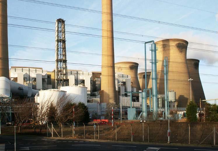
18 Demonstration Projects CCPilot100+ SSE Ferrybridge CCPilot t/day CO 2 PCC Demonstration Plant Post Combustion Capture Demonstration Plant using Doosan Power System s technology 100 t/day slip stream on SSE s Ferrybridge Power Station Largest PCC Demonstration in the UK Funding by the project partners, Scottish & Southern Energy, Vattenfall, Doosan Power Systems, TSB, DECC and The Northern Way. Fast track, for operation during 2011 Two year test programme Lessons learned will be incorporated into future designs Off gas analysis amine carryover and degradation products On-site amine and degradation product atmospheric sampling and analysis University of Leeds 17
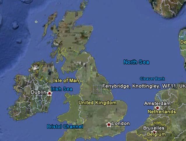
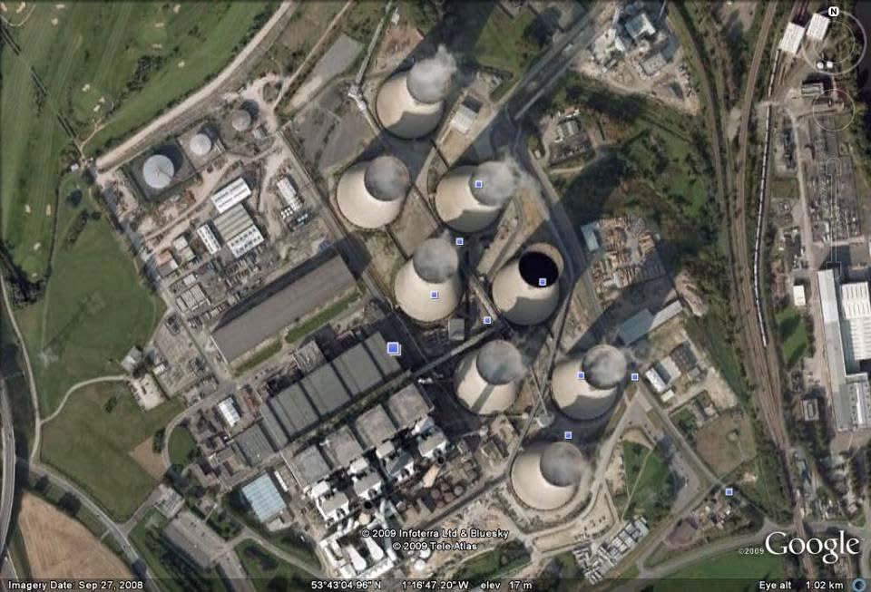
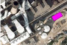
19 CCPilot100+ Project Location 18 Pictures courtesy Google Earth
 100 metric tpd 90% 2.3 x 39 Doosan Power Systems Stripper Column Dimensions (i.dia x height; m) 1.1 x 30.")
20 CCPilot100+ Process Layout and Key Parameters Direct Contact Cooler CO 2 Absorber Polishing FGD CO 2 Stripper Column PCC Design Design CO2 removal efficiency CO2 Absorber Dimensions (i.dia x height; m) 100 metric tpd 90% 2.3 x 39 Doosan Power Systems Stripper Column Dimensions (i.dia x height; m) 1.1 x


21 CCPilot100+ Project Execution Current Status In Construction Absorber Fabrication Simulation Stripper Column Delivery P&IDs 3D Modelling Construction Testing Programme 20

22 Case Study Basin Electric FEED Sized to capture 1.0 MM tons per year of CO 2 from Basin Electric s Antelope Valley Power Plant 3,000 tons per day Treating a ~ 120 MW slipstream Turnkey EPC Scope including: PCC plant, FGD polishing and CO 2 compression and dehydration Key FEED Deliverables: Engineering studies to investigate the integration of the PCCC Plant within the existing AVS and DGC infrastructure Proposed EPC Scope of Work, based upon the final design of the PCC Plant 15% EPC CAPEX and OPEX Estimate Level 2 EPC Project Schedule Project currently deferred by client Basin Electric Antelope Valley Station (in background) and Dakota Gasification Facility (in foreground) 21
 CO2 Absorber Dimensions (dia x height; m) Stripper Column Dimensions (dia x height; m) 1,544,000 lb/hr 90% 9.5 x 14.8 11.8 x 53.3 5.6 x 36.")
23 Basin Electric Process Layout and Key Parameters Polishing FGD Direct Contact Cooler CO 2 Stripper Column Existing Stack Offgas Return CO 2 Absorber PCC Design Gas Flow (lb/hr) Design CO2 removal efficiency DCC Absorber Dimensions (dia x height; m) CO2 Absorber Dimensions (dia x height; m) Stripper Column Dimensions (dia x height; m) 1,544,000 lb/hr 90% 9.5 x x x
24 Basin Electric - Boundary Dam 10-Day Test Run Equivalent Steam Steam (kg/kg) /08/ :02 09/08/ :07 09/09/ :22 09/09/ :27 09/09/ :42 09/10/ :22 09/10/ :27 09/10/ :57 09/10/ :02 09/11/ :12 09/11/ :17 09/11/ :03 09/11/ :02 09/12/ :07 09/12/ :12 09/12/ :02 09/12/ :27 9/13/2010 3:32:24 AM 9/13/ :17:24 AM 9/13/2010 4:17:27 PM 9/13/ :22:27 PM 9/14/2010 4:27:28 AM 9/14/2010 2:17:31 PM 9/14/2010 8:17:32 PM 9/15/2010 2:27:34 AM 9/15/2010 8:37:35 AM 9/15/2010 2:47:37 PM 9/15/2010 9:07:38 PM 9/16/2010 3:17:39 AM 9/16/2010 9:37:40 AM 9/16/2010 3:47:42 PM 9/16/2010 9:52:42 PM 9/17/2010 4:12:44 AM 9/17/ :47:45 AM 9/17/2010 5:42:47 PM 9/20/2010 1:57:16 PM 9/20/2010 8:07:18 PM 9/21/2010 2:12:18 AM 9/21/2010 8:37:20 AM Date/Time Ambient Temp ( C) Prod Steam CO2 Mass Ratio Average Heat Duty AmbientCelcius 23


25 In Summary Doosan utilises process technology that was invented and developed in Canada by UoR and HTC Purenergy, Inc. Doosan and HTC are at the forefront of PCC technology development Doosan has a proven highly efficient process and product which it will guarantee Doosan will undertake full EPC Doosan have available resources and can leverage the historic experience from recent projects to achieve clients goals Low impact, high efficiency, integrated EPC Carbon Capture Solutions 24
26 THANK YOU