Piotr Lampart. New IMP PAN research - renewable energy technologies
|
|
|
- Bertha Skinner
- 5 years ago
- Views:
Transcription

1 ERCOFTAC Spring Festival 2011 Piotr Lampart New IMP PAN research - renewable energy technologies Gdańsk, 12 May 2011

2 SAMPLE IMP PAN / BKEE PROJECTS Model agro-energy complexes in distributed coegeneration of heat and power Key Project of POIG Head Prof. J. Kiciński Advanced technologies for energy production. Task 4. Elaboration of integrated technologies for the production of fuels and energy from biomass, agricultural waste and other waste materials Strategic Programme of NCBiR Head Prof. J. Kiciński The Baltic Sea Bioenergy Promotion Programme INTERREG IV C Border-free energy care NORWEGIAN FINANSE MECHANISM Evnironmet-friendly energy development of communes (gminas) NORWEGIAN FINANSE MECHANISM

3 Aims of the Strategic Programme Elaboration of technologies for the production of biofuels integrated with cogeneration of electric and heat. Elaboration of documentation of a series of distributed energy systems Preparation of demo instalations ready for implementations in energy industry
4 Main research areas Cogeneration of electric energy and heat from biomass/biogas Micro-biogas stations High-temperature gasification of biomass and waste Biomass fermentation to biogas Biorafinery Fuel cells and cogeneration on SOFC Pufirication of biogas and syngas Microgrids Small wind and water turbines, hybrid RES
5 Demo instalation ORC cogeneration complex (0.15MWe) Thermal oil loop 295 o C/235 o C Silica oil loop: - turbine bar/250 o C bar/210 o C - recuperator vapour 210/120 o C, liquid 90/175 o C - preheater 175 o C/250 o C - evaporator o C - condenser - 90 o C - Hot water (summer) 65 o C/45 o C, Medium silica oil


6 Heat station upgrade Closing 3 coal boilers Instalation of a biomass fired ORC system (0.8MWth, 0.15MWe) Installation of a natural gas fired cogeneration system based on two piston engines (3.5MWth, 3.2MWe) Installation of a biomass fired steam cogeneration system (5.2MWth, 2.7 MWe) Modernisation of 1 coal boiler (10MWt)


7 Demo instalation - cogeneration system for a biomass processing factory Gas reactor, Syngas purification system, Piston combustion engine with generator 0.5MW, Heat recovery system for biomass drying.
 Thermal oil loop - 260 o C/200 o C Medium loop (HFE 7100): - turbine - 15 bar/170 o C - 2 bar/130 o C - recuperator vapour 130/80 o C, liquid 70/100 o C - preheater 1 90 o")
8 Demo installation - cogeneration gas / ORC cycle (0.6MWe) Thermal oil loop o C/200 o C Medium loop (HFE 7100): - turbine - 15 bar/170 o C - 2 bar/130 o C - recuperator vapour 130/80 o C, liquid 70/100 o C - preheater 1 90 o C/170 o C - preheater 2 70 o C/85 o C - evaporator o C - condenser - 80 o C - Hot water (summer) 65 o C/45 o C, Medium HFE 7100
9 COGENERATION specific research topics: - Theoretical, numerical and experimental investigations of combustion of low-caloric gases in piston engines and gas turbines - Development of supply and ignition control systems for cogeneration engines fired by low caloric gases - Theoretical, numerical and experimental investigation of poligeneration ORC cycles - Investigation of thermodynamics properties of ORC fluids - Investigation of aerodynamics and dynamics of micro- and mini-scale high-rotation turbogenerators - Investigation of cogeneration cycles based on recovery heat


10 Small wind turbines at IMPPAN Source: P. Doerffer Vertical axis turbine Horizontal axis turbine Main interest 1-3 kw Customer tailored kw W I N D Vertical axis Counter-rotating drums Upwind elements covered.
 4...7 m (28%) spad H = 2...4 m (45%) Innovation Source: A.")
 m sł. wody Flow: Q = (0.")
11 Micro hydro power: Low-head turbines Why small hydro power should be developed? Head structure in Poland - almost 50% are low-head objects, not used m m (15%) m (28%) spad H = m (45%) Innovation Source: A. Adamkowski New blading systems of high a rotation coefficient, Control system for adjustable rotational velocity, New design methods, Optimisation of usage of water resources. Low-head hydro turbine parameters: Head: H = (1.5 4 ) m sł. wody Flow: Q = (0.3 12) m 3 /s Power: P e = (10 350) kw Expected efficiency: η = (75 85)% Rotation coefficient: n SQ = ( )


12 Hybrid RES Energy production systems that draw on two or more energy sources Good points: - Overcome shortages of single source, - Guarantee continuous supply, - Guarantee less fuel consumption and emissions, - HYRES promote RES. Examples: wind turbine / PV / battery, wind turbine / compressor / compressed air tank / gas turbine, wind turbine / PV / diesel engine / battery, PV / PEM, wind farm / hydro pumped-storage, spark engine / electric engine, solar panels / ground heat store / heat pump / air-conditioning, solar panels / biomass boiler. Source: Ashikaga Inst.Tech.
13 Partial admission turbines - Partial admission increases internal efficiency of small turbines - Partial admission introduces strong circumferential non-symmetry of flow parameters in the control stage and is a cause of additional unsteady loads of the rotor blades. - Due to a rapid change of load while entering and leaving the arc of admission, the rotor blades and also blade-fit regions experience higher unsteady mechanical stresses and are more vulnerable to failure. The operation of the partial admission stage gives also rise to excessive low-frequency excitations that may be dangerous for the dynamics of the system of rotor shaft, bearings and supports. Source: P. Lampart, M. Szymaniak

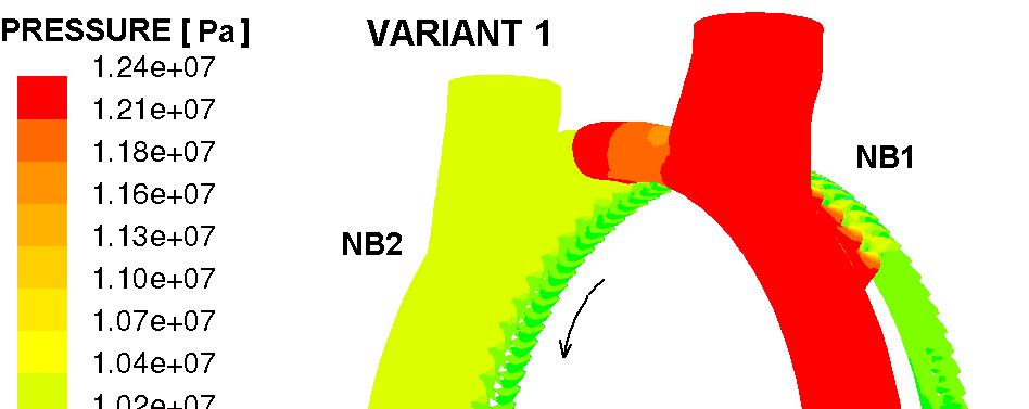
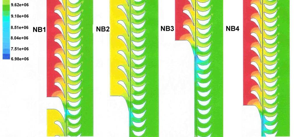
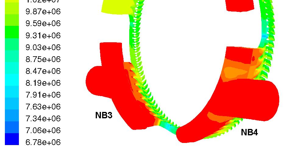
14 Partial admission turbines Instantaneous isolines of static pressure in the control stage cascades

15 Partial admission turbines SINGLE ROTOR BLADE LOAD (2D mid-span)


16 Partial admission turbines EFFECTS OF ROTOR BLADE MISTUNING OR GEOMETRICAL IMPERFECTION Schematic of changes in control stage rotor geometry. Packages of blades with different blade thickness.


17 Tesla type Friction turbines TESLA: n=18 000, SES36, p in = 13,8 bar, T in =400K, G = 0,38 kg/s, P = 1,63 kw Source: P. Lampart K. Kosowski Ł. Jędrzejewski
18 Adaptive control in LP cogeneration turbines Cogeneration of electric energy and heat in heat and power turbines requires application of adaptive control to adapt them to variable operating conditions. The main element of adaptive control is the so-called adaptive stage of flexible geometry located directly downstream of the extraction point. Throttling nozzles (LMZ, ABB-Zamech, Alstom) Source: P. Lampart R. Puzyrewski
19 The effect of adaptive control based on flap nozzles in a group of two LP stages in the case of cogeneration of electric energy and heat. nominal o/p (N): m N = 35.6 kg/s, p N = bar, ζ L-1 = 12%, N L-1 = 3.7MW, ζ L = 20%, N L = 2.8MW; N A m u = 3.6 kg/s, m A = 32 kg/s, p 2A = 0.25 bar, ζ L-1 = 23%, N L-1 = 1.6MW ζ L > 100%, N L = -0.5MW LP part of 60 MW extraction/condensing turbine A A (-1.8 o ) m A = 32 kg/s, p 2A = 0.10 bar, ζ L-1 = 13%, N L-1 = 3.8MW ζ L = 22%, N L = 2.1MW

20 COGENERATION TURBINE PREHEATING at START-UP During start-up from a cold state the metal temperature increases by 500K This is accompanied by elongation of the metal and increase of stresses in the metal Relative elongations of casing and rotor appear. Clearances are reduced. Friction of metal against metal can occur. Frequent changes of heat load and large heating rates lead to increased unsteady stresses, then thermal fatigue and metal cracking Permanent deformations can occur Source: R. Rządkowski P. Lampart
21 HEATING-UP PROCEDURE First phases condensation heat transfer. Dewatering system is open until superheated steam appears at the exit. Subsequent phases convective heat transfer from superheated steam. Measurement of absolute and relative elongations If maximum values are exceeded turbine is shut down CFD CALCULATIONS (PROGRAM FLUENT) Conjugated heat and flow calculations: - within the flow region (blading system, sealings, intercasing chambers, inlet and outlet pipes - model RANS - within the metal region (shaft, inner casing, outer casing, shield) energy conservation equation - boundary conditions no heat flow at the shield Evaluation of surface heat flux to the casing and rotor
 115 min Control valves successive opening Live steam supply.")
22 30 min 60 min Cut-off valve closed Steam supplied to the outlet Saturation temperature T s = o C Film condensation heat transfer Control valves closed Steam supplied to the intercasing space. Live steam at the inlet Convective heat transfer from superheated steam (condensation at the inlet pipe) 115 min Control valves successive opening Live steam supply. Rotational velocity increase Heat transfer from superheated steam

23 30 min IN C0 CTRL ST G1GP C1C2 C3G2 Temperature in the fluid, metal and shield after 30 min of heating [K]


24 60 min IN C0 CTRL ST G1GP C1C2 C3G2 Temperature in the fluid, metal and shield after 60 min of heating [K]


25 135 min IN C0 CTRL ST G1GP C1C2 C3G2 Temperature in the fluid, metal and shield after 135 min of heating [K]


26 Mean surface heat flux during turbine preheating
27 Expansion of shaft and casing (case 3) [mm] Time [min] Relative expansion of shaft (exp.) Absolute expansion of outer casing (exp.) Absolute expansion of shaft (exp.) Absolute expansion of outer casing (calc.) Absolute expansion of shaft (calc.) Relative expansion of shaft (calc.) Relative and absolute expansions of casing and shaft