DLE-H LINEAR ENCLOSURE DISPLACEMENT DIFFUSER WITH INTEGRAL HEAT
|
|
|
- Gilbert Cain
- 5 years ago
- Views:
Transcription

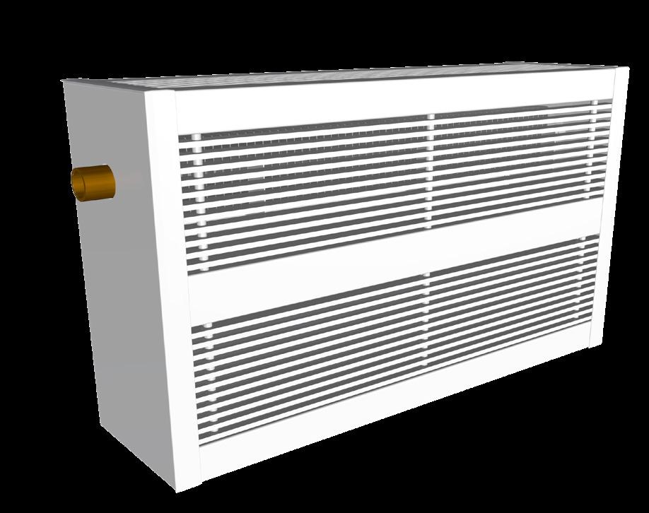
1 LINEAR ENCLOSURE DISPLACEMENT DIFFUSER WITH INTEGRAL HEAT


2 The (DLE-H) uniquely combines natural convective heating with low level displacement cooling into one cabinet enclosure. The heating option is ideal for conditioning the perimeter while still providing superior air quality. The DLE-H is equipped with a fin tube or electric heater that in heating mode allows the unit to pull cool air through the face, warm it, and discharge the air upwards along a cool window similar to a baseboard heater. This helps to eliminate draft and frosting of a cool exterior window. The DLE, with its pencil proof bar grille, is designed to be mounted along the perimeter, sidewalls and even integrated into shelving. Typical applications include classrooms, cafeterias and multi-functional spaces. DLE-H Cooling airflow Heating airflow CONSTRUCTION + + Material Inner Baffle and Mandrel tubes - Aluminum Outer Shell and End Caps - Steel Optional Construction - Aluminum + + Options Blank-off section to cover junctions Ships with protective film on face ETL Certified 120V, 208V, and 240V heater options available SCR or 24VAC heater controller Standard Finishes: B12 White, B15 Grey, B17 Black, and B11 Pure White Optional Finishes: PC12 Prime Powder Coat and B25 color to match 2 For more information visit v001
3 DIMENSIONAL DATA "Z" ENDCAP ADDS 1/1 TO LENGTH "Z" ENDCAP ADDS 1/1 TO LENGTH "Z" ENDCAP ADDS 1/1 TO LENGTH DLE-H DISPLACEMENT DLE-H DISPLACEMENT LINEAR ENCLOSURE LINEAR ENCLOSURE DLE TYPE 25C CORE PENCIL PROOF 0 DEFLECTION. 7/1 SPACING DETAIL A NOM LENGTH - 3/4 IN. (WITHOUT ENDCAPS / SPLICES) NOM LENGTH - 3/4 IN. (WITHOUT ENDCAPS / SPLICES) NOM LENGTH - 3/4 IN. (WITHOUT ENDCAPS / SPLICES) SPLICE FOR "Y" END CONDITION SPLICE FOR "Y" END CONDITION SPLICE FOR "Y" END CONDITION Hydronic Heater Hydronic Heater - Dimensions Hydronic Heater - Dimensions Electric Heater - Dimensions Heater Electric Heater - Dimensions HEATING HEATING 8 1/4 IN. 8 1/4 IN. REF FIN TUBE LOCATION REF FIN TUBE LOCATION 12 1/4 IN. ELECTRIC HEATER 12 1/4 IN. ELECTRIC HEATER INSULATION INSULATION 7/1 SPACING A DISPLACEMENT A 7/1 SPACING 20 IN. DISPLACEMENT 24 IN. 28 IN. 20 INSULATION IN. 24 IN. 28 IN. DISPLACEMENT INSULATION DISPLACEMENT Nominal Size - Hydronic Heater Length (in.) Height (in.) , 20, Nominal Size - Electric Heater Length (in.) Height (in.) , 24, Note: The cooling performance for the hydronic and electric units will be different due to a difference in the heights of the heating sections. v001 For more information visit 3
4 PERFORMANCE DATA Cooling: Electric Heat Option Unit Size L x H [in] 30 x x x x x x x x x x x x 28 Face Total Static Noise Proximity to Outlet [ft] Air Flow Velocity Pressure Pressure Criteria DR 20% Adjacent Zone [cfm] [fpm] [in. w.g.] [in. w.g.] [NC] T = 5 F T = 10 F T = 5 F T = 10 F Performance Notes: 1. Sound and pressure drop tested in accordance with ASHRAE Standard Method of Testing for Rating the Performance of Air Outlets and Inlets. 2. Air flow is in cubic feet per minute, cfm. 3. Pressure is in inches of water, in. w.g. 4. The NC values, sound pressure level, are based on a room absorption of 10 db, re watts and one diffuser. 5. T is the difference between the room air temperature 3½ ft above the floor and the temperature of the supply air. Electric Heating Performance Nom. Length (in.) Heater Output 120V 208V 240V W 375W 500W W 375W 500W W 750W 1000W W 750W 1000W 6. Proximity to outlet is the minimum distance from an outlet to the occupant in order to achieve the listed DR value. 7. Distances closer to the diffuser have a higher DR than the cataloged value. 8. DR is the predicted percentage of people dissatisfied (PPD) due to draft. A value of less than 20 meets the requirements of ASHRAE Standard , Thermal Environmental Conditions for Human Occupancy. 9. Blanks - indicate that the DR is below the specified value at all distances from the diffuser face. Note: The cooling for performance for the hydrnoic and electric units will be different due to a difference in the heights of the heating sections. 10. DR catalog data is presented for an occupant density of 25 people/1000ft 2, which is the default occupancy density for classrooms (ages 5-8) given by ASHRAE For other occupant densities, please refer to the DV Room Designer Software. 11. The Adjacent zone describes the distance from the face of the diffuser and measured 1 in. from the floor, at which the supply air velocity is 50 fpm. 4 For more information visit v001
5 PERFORMANCE DATA Cooling: Hydronic Heating Option Unit Size L x H [in] 24 x x x x x x x x x x x x 24 Face Total Static Noise Proximity to Outlet [ft] Air Flow Velocity Pressure Pressure Criteria DR 20% Adjacent Zone [cfm] [fpm] [in. w.g.] [in. w.g.] [NC] T = 5 F T = 10 F T = 5 F T = 10 F Performance Notes: 1. Sound and pressure drop tested in accordance with ASHRAE Standard Method of Testing for Rating the Performance of Air Outlets and Inlets. 2. Air flow is in cubic feet per minute, cfm. 3. Pressure is in inches of water, in. w.g. 4. The NC values, sound pressure level, are based on a room absorption of 10 db, re watts and one diffuser. 5. T is the difference between the room air temperature 3 ½ ft above the floor and the temperature of the supply air. 6. Proximity to outlet is the minimum distance from an outlet to the occupant in order to achieve the listed DR value. 7. Distances closer to the diffuser have a higher DR than the cataloged value. 8. DR is the predicted percentage of people dissatisfied (PPD) due to draft. A value of less than 20 meets the requirements of ASHRAE Standard , Thermal Environmental Conditions for Human Occupancy. 9. Blanks - indicate that the DR is below the specified value at all distances from the diffuser face. 10. DR catalog data is presented for an occupant density of 25 people/1000ft 2, which is the default occupancy density for classrooms (ages 5-8) given by ASHRAE For other occupant densities, please refer to the DV Room Designer Software. 11. The Adjacent zone describes the distance from the face of the diffuser and measured 1 in. from the floor, at which the supply air velocity is 50 fpm. v001 For more information visit 5
6 Product Improvement is a continuing endeavour at Price. Therefore, specifications are subject to change without notice. Consult your Price Sales Representative for current specifications or more detailed information. Not all products may be available in all geographic areas. All goods described in this document are warranted as described in the Limited Warranty shown at priceindustries.com. The complete Price product catalog can be viewed online at priceindustries.com. Price is a registered trademark of Price Industries Limited Printed in Canada. v001