Thermal Remediation Technology Overview and Practical Applications
|
|
|
- Margaret Short
- 5 years ago
- Views:
Transcription
1 Thermal Remediation Technology Overview and Practical Applications Rhode Island Society of Environmental Professionals Tuesday December 5, 2017 Steffen Griepke Nielsen and John Haas TerraTherm, Inc.
2 Goals / Objectives Provide you with an understanding of thermal remediation, the different heating methods, and where each one fits Learn more about what the technologies are and when to consider thermal Understand the strengths and weaknesses for each technology Provide you with several project profiles 2


3 In Situ Thermal Treatment 1. Size - Many boreholes - More than 5,000 ft 2 - More than 3,000 cy - Deeper than 10 ft 2. Organics, high mass - Source areas - We love CVOCs - Large mass DNAPL - Heavy decontamination 3. Driver Note: Sample composed of silty sand impacted with coal tar. 3


4 Technology Fit vs. Mass/Concentrations NAPL pools Mobile NAPL Ganglia Droplets Adsorbed/dissolved Trace Note: Sample composed of silty sand impacted with coal tar. Concentration Thermal ISCO/ISCR ISB MNA 4

5 Thermal Removal Mechanisms VOCs and Lighter SVOCs 100 C Volatilization and Steam Stripping VOCs = Volatile Organic Compounds SVOCs = Semi-VOCs 5

6 Volatilization and Steam Stripping NAPL And Water Boiling Interpreted mechanism steam and VOC vaporization 6

7 Thermal Removal Mechanisms Physical Displacement of High Boiling Point NAPLs Enhanced with Heating 7

8 Thermal Removal Mechanisms Thermo-Chemical Stabilization of NAPL with Heating Light ends are removed from Diesel Range NAPL at 100 C Typical Soil Chromatogram Before Thermal Treatment Soil Residual Chromatogram After Thermal Treatment 8
9 Thermal Removal Mechanisms Vapor Pressures Increase Exponentially During Heating 9


10 Three Levels of Thermal Treatment 100 C 70 C 325 C Level 2 Treatment at 100 C Level 1 Thermally enhanced NAPL recovery Level 3 Complete COC removal/destruction 10
11 And Then Level 0 was added! Thermally Enhanced Biodegradation At an ISTR Site, heat accelerates dissolution/desorption but also accelerates biodegradation rates of petroleum hydrocarbons and chlorinated solvents. Petroleum - BTEX biodegradation has been shown to triple (3X) from 10 to 20 C and petroleum hydrocarbon biodegradation rates have shown peak degradation rates between 30 and 40 C. Chlorinated Solvents - Up to approximately 40 C, dechlorination rates are expected to double with every 10 C increase in subsurface temperature. Due to: Population Growth Electron Availability (release from organic material) Metabolic Rates/Degradation Rate 11


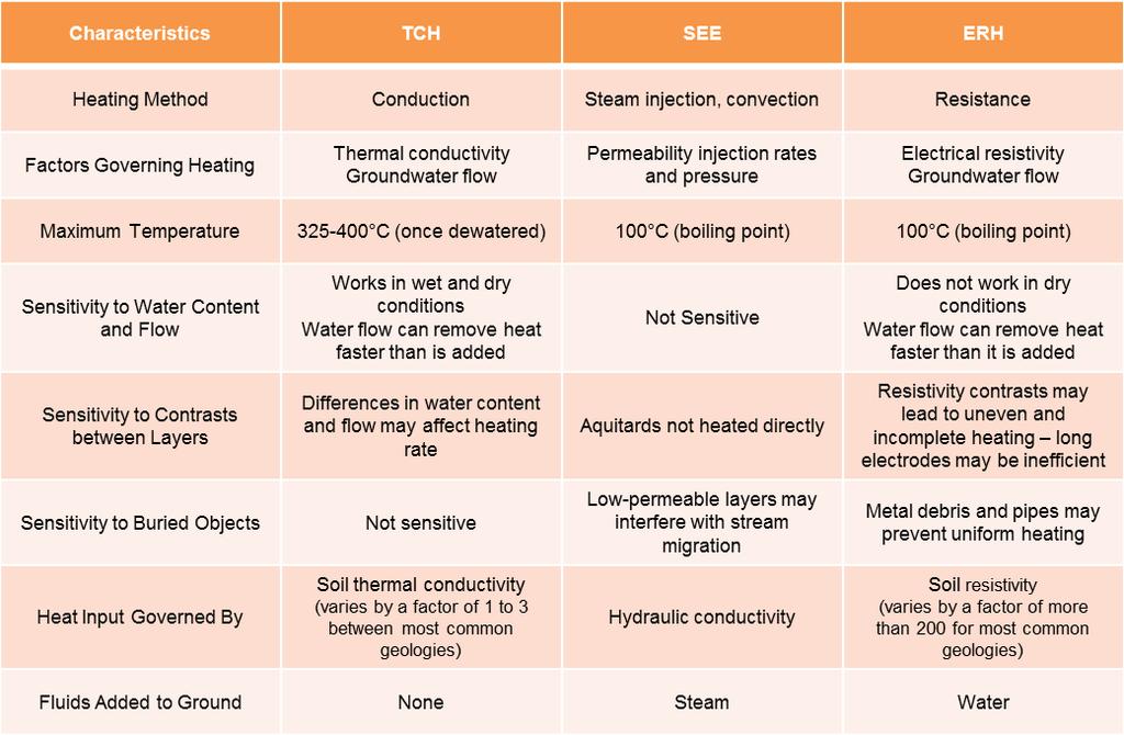
12 Heating Methods For sites with volatile or moderately volatile contaminants particularly in shallow settings. Applicable in permeable sites with significant groundwater flow and for sites with volatile or moderately volatile contaminants. For all sites with low to moderate groundwater flow rates and either Volatile Organic Compounds (VOCs) or Semi-Volatile Organic Compounds (SVOCs). 12
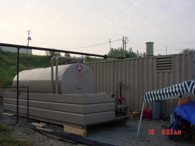
13 Four Step ISTR Process HEAT EXTRACT COOL TREAT Steam COC Vapors Pumpable Fluids SVE MPE Pumps Condensate COC Vapors NAPL POTW GAC/Oxidizer Recycle

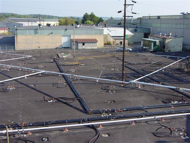
14 Conceptual Model - Typical ISTR System 14
15 Conceptual Model - Typical DNAPL Site Silt GW Sand Plume Sand Silt GW = groundwater 15
16 Thermal Conduction Heating (TCH) Electric Heaters Contaminant Vapors and Steam Rate and Uniformity of Heating Governed by Thermal Conductivity GW Flux < 1 ft/day Varies by a Factor of ~4 TCH + vacuum extraction = In Situ Thermal Desorption (ISTD) 16

17 Electric TCH Heaters 17


18

19 Two Ways to Apply TCH In Place (In Situ) or Aboveground (Ex Situ) IPTD for Ex-Situ Soil Remediation ISTD for In-Situ Source Removal 19

20 HB1100 Heated Box U.S. Patents 8,348,551 and 8,562,252 issued in International patents issued and pending. 20


21 HB1100 Pilot Study Demonstration $ per cubic yard 2,000-12,000 cy sweet-spot 21

22 Example Three-Unit Treatment Scenario Treatment System Box 1 Box 2 SCR Cabinet Soil Box 3 Box lid set aside for load and unload 22
23 Electrical Resistance Heating (ERH) V +/- Contaminant Vapors, Steam, and Liquids V +/- Rate and Uniformity of Heating Governed by Soil Resistivity Varies by a Factor of ~200 Hot Tight Soil Lenses Focus Current Tight Soil Lenses DNAPL 23
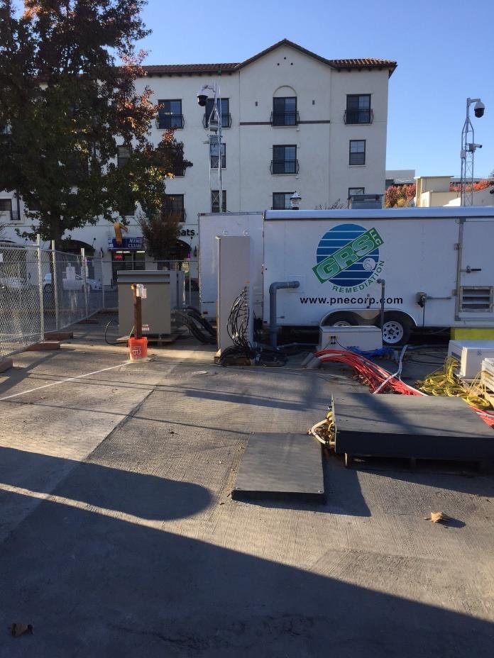
24 ERH Electrode Design Cascade Thermal Services - GRS 24

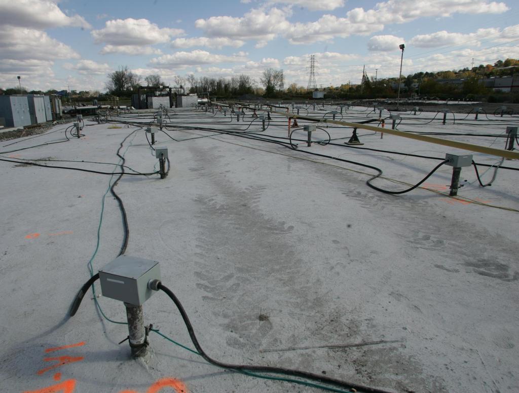
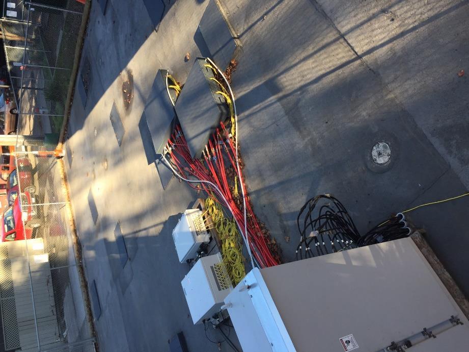
25 ERH Well Field Power Distribution System For Electrodes Electrodes Vapor and Liquid Manifolds 25
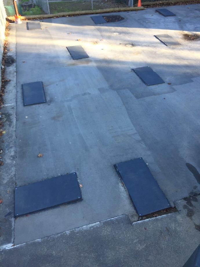
26 Subsurface ERH Well Field 26
27 Steam Enhanced Extraction (SEE) Steam Contaminant Vapors, Steam, and Liquids Steam Rate and Uniformity of Heating Governed by Soil Permeability Varies by a factor of 10 2 to 10 4 K > 5 x 10⁻⁴ cm/sec K = Hydraulic conductivity 27


28 Steam Injection Manifold Important to Regulate and Measure Steam Injection Rates Into Individual Wells/Zones (SteamTech) (NIRAS) 28


29 29


30 SEE Pilot CVOCs and LNAPL Use Outside-In Approach to Minimize Potential For Mobilization of Contaminants Outside of Treatment Zone (after SteamTech) 30
31 ISTR Technologies 31
32 Sometimes One Technology Alone Won t Get The Job Done Contaminant Vapors and Steam GW GW Flux > 1 ft/day 32
33 Combined ISTR Approaches Combined ISTR Technologies TCH-SEE ERH-SEE ERH-TCH ISTR Biodegradation (Heat Enhanced Bio) Post ISTR Bio-polishing Low Temp ISTR Heat Enhanced Bio ISTR Source Enhanced Bio Downgradient Plume 33

34 Combine ISTR Technologies To Match Site Conditions ERH/TCH Combination 34


35 Example ERH-TCH Site 35

36 Example TCH-SEE Site 36

_")
37 Previous Project: SRSNE Superfund Site One of New England s larger hazardous waste sites 1.75 acre TCH project Met goals; 500,000 lbs. mass removed (May 2014 to Feb 2015)_ Demobilization complete 37


38 Previous Project: Silresim Chemical Corp Silresim Chemical Corporation, Lowell, MA COCs: Chlorobenzene, TCE, PCE, BTEX 304 Electrodes in 144 electrode borings 34 VEWs, 77 MPEs, and 55 TMPs Results: Goal was to remove mass Approx 55,565 cy treated over a 49,400 ft 2 area More than 90,000 lbs of COCs removed 38


39 Current Project: Danang Airport, Vietnam $37M Dioxin cleanup underway Confirmatory sampling of Phase 1 Complete Phase 2 Complete 39


40 Recent Project: Former Williams AFB, Mesa, AZ Largest in situ thermal remediation project in the world Treatment volume of approx. 410,000 yd 3, 250 feet bgs >2.6 Million lbs. NAPL removed (406 days in operation) 40
41 What About The Cost? $/cy 100 Complex Simple 10,000 20,000 30,000 40,000 Volume (cy) 41
42 Duration 42

43 Thermal Summary 1. Source zones 2. Significant COC mass 3. Low cleanup targets 4. Remediation driver 5. Bio applications Include the thermal vendor to select the most appropriate thermal technology and approach for your job. 43