DEVELOPMENT ON MICROWIND TURBINE FOR AUTOMOTIVES
|
|
|
- Georgiana Fowler
- 5 years ago
- Views:
Transcription
1 DEVELOPMENT ON MICROWIND TURBINE FOR AUTOMOTIVES *S.Premkumar, **S.Rajakumar *PG student, ** Assistant Professor Department of Mechanical Engineering, Regional centre, Anna University Tirunelveli Region, Tirunelveli, India ABSTRACT In this study, the performance of micro wind turbine in automobile will be completed. Fabrication work will be finished by using composite material of wood to design a blade experimentation.consists an input parameters as a wind speed (m/s),open circuit voltage (V oc ),current (A),voltage(V)and rotor frequency(hz) for the responses such as kinetic energy,mass flow of air, wind power, power coefficient, rotor rotational speed, mechanical angular speed and tip speed ratio(tsr) are considered. This proposed research work is aimed to decrease the fuel consumption and to improve the utilisation of the renewable energy.in this study, design, implementation and power performance analyses of a Micro Wind Turbine (MWT) system a represent.an original Permanent Magnet Synchronous Generator(PMSR)that reduced cogging torque was utilized for the MWT blade.power performance are carried out in different wind ranges.more over, it is used in vehicle interior like Head lamp, Ac, Top light on body vehicle Key Words: Energy, Renewable energy, Wind energy, Micro wind turbine. 1. INTRODUCTION Recently wind turbine energy has become one of the mostly rapidly increasing renewable energy resources. One of the methods for converting electrical energy into wind energy is to use wind turbine (WTs). WTs are manufactured for different sizes and power. According to the IEC standard of the International Electro technical Commission (IEC), WTs are divided into two classes: Small WTs (SWT) and Large WTs (LWT). Commercially manufactured SWTs are analyzed in Three classes: Micro WTs (MWT), Small WTs (SWT)and Small-Medium WTs(SMWT). On account of the installation costs of MWTs. it is basically consists of a generator, 3 blades, a tail, a tower, and electrical equipment. There are two types of blade axes MWTs: VAWTs and HAWTs.The cut-in of a VAWT is lower than that of a HAWT are perpendicular, and the rotation axis is parallel to the direction of wind. There are upwind and downwind types of them. MWTs could be manufactured with gear mechanism and drive drives. Recently, a large number of them have been manufactured with direct drives. 96
2 2. CONCEPTS OF FAN PRESSURES: The flow of air between two zones is due to a pressure difference between the two zones. This pressure difference forces the air to flow from the high-pressure zone to the lowpressure zone. The flow of air through a system requires energy to overcome any static pressure at the entry or outlet of the system. 3. APPLICATIONS OF WIND ENERGY 3.1 Energy-generating wind turbines: Wind turbines are installed to capture the power of the wind and be able to convert it to energy. This can be on a broad scale, such as the wind turbines found on wind farms or can be on a smaller scale, such as individual wind turbines people use to generate power for their home. Companies even want to take advantage of the wind 3.2 Wind-powered vehicles: You ve probably heard about this one recently. A car, powered primarily by wind (using kites), just completed a 3,100 mile journey across Australia. While it wasn t 100% powered by the wind, it was a good example of how cars can also be powered using alternative energies. It used a combination of wind, kite and batteries. In total, it reportedly used about $10-$15 of energy for the entire 3,100 mile journey. 4. DRAG FORCE: In fluid dynamics, drag (sometimes called air resistance or fluid resistance) refers to forces that oppose the relative motion of an object through a fluid (a liquid or gas). Drag forces act in a direction opposite to the oncoming flow velocity. Unlike other resistive forces such as dry friction, which is nearly independent of velocity, drag forces depend on velocity. For a solid object moving through a fluid, the drag is the component of the net aerodynamic or hydrodynamic force acting opposite to the direction of the movement. 4.1 The force on a moving object: The main objective of our project is to convert wind energy into electric energy. By installing this device as shown in figure we can run audio system, mobile charging application, etc. To run any electric system, electric power from a battery or engine power is essential, so by installing this device, we can save the engine power which can be further utilized to run the vehicle which also leads to saving of fuel and/or in turn charge the battery. As shown in Figure, the drag and thrust force acts on a moving vehicle. The drag force can be used for useful electrical energy generation which in turn may either be stored in a battery or used to run a electrical utility. The detailed drawing of a wind energy convertor system converting the drag force of wind into useful electrical power. 97
3 5. BLADE SPEED AND RPM: Proper wheel design must be closely correlated with blade speed sin the total pressure furnished by any wheel is proportional to the square of the Rpm. The hub diameter, pitch, blade angle, number of blades and the deflection of the air stream all depend up on the Rpm of the unit for a given performance; a lower Rpm will require a greater number of blades for the same hub diameter. Still lower Rpm maybe obtained in a higher series with a larger hub diameter since it is necessary that the slowest portion of the blades, which is the portion to the hub, be travelling at sufficient speed and have sufficient surface to accomplish the required performance. As a result, the lower the speed, the large the hub required to achieve the necessary peripheral velocity. In a given wheel under fixed conditions, an increase in Rpm will result on a horse power increase proportional to the cube of the Rpm for this reason, variable speed units cannot be expected to achieve greatly increased airflow without excessive horse power gain 6.ROTOR DIMENSION: The conversion of wind power into mechanical energy has a theoretical limit efficiency of 59.3% using simple fluid dynamics equation. In practice, most current wind turbine operate at an efficiency close to40%.the kinetic power of wind within a certain area can be expressed as: P kinetic =(1/2)A V After the wind to mechanical conversion and the mechanical to electric conversion losses. We are left with the equation: Using an air density of1.23 kg/ma power output of 1.5W a design wind speed of 6m/sand efficiencies of n=0.7 and n=0.4. We obtain an approximate diameter of 20-25cm 7. DESIGN SPECIFICATION: There are many parameters and variables that need to be evaluated and selected prior to the design of a wind turbine rotor. Number of blades: The number of blades does not have a significant impact on the efficiency of a wind turbine. We have chosen a two blade design because of ease of fabrication in order to keep manufacturing costs low. 8. AIRFOIL: The airfoil needs to be optimized in order to have the best Lift/Drag ratio. The Reynolds number is an indicator of the wind speed and the dimensions of the blade and is key in choosing the correct airfoil profile. In our case, the Reynolds number is around25, 0z00. 98
 can be defined as the speed of the tip of the blade divided by the speed of the wind.")
4 Cross-section diagram of blade with shear web Blade weight with respect to blade length, actual data from commercial wind turbine blades. 8.1 TYPES OF AEROFOIL: Asymmetrical aerofoil. Symmetric aerofoil. 9. DESIGN TIP SPEED RATIO: Designing composite wind turbine blades The Tip Speed Ratio (TSR) can be defined as the speed of the tip of the blade divided by the speed of the wind. This value is crucial as it will influence the design of the blade, the operational RPM and the efficiency. Depending on the number of blades of a rotor, each turbine is designed to operate at a particular TSR to obtain maximum efficiency. 99
5 10. DESIGN CHORD AND TWIST: Using simple fluid mechanics, it is possible to demonstrate that the chord length that will optimize lift at each cross-section of the blade is given by : Chord(r)=16πR 2 /9rλ 2 BCl Where: R=Total Radius B=Number of blades λ=design Tip Speed Ratio Cl=Lift coefficient In a similar manner, we can express the optimal twist of the blade at each section of the blade by: β(r)= ATAN( 2R ) α/3rλ Where: R=Total Radius λ=design Tip Speed Ratio α=angle of attack Given an airfoil, the design tip speed ratio is the first parameter that used in a blade design procedure, which is generally taken as 6-8 in modem wind turbines. But the optimum value remains uncertain for different aerofoil shape sand blade numbers. It was has an optimum tip speed ratio of 8.5 while L8-1 has an optimum value of lo in 3-blade turbines.as a higher lift coefficient means a larger lift force, a higher drag coefficient means a larger drag force, a turbine with the aerofoil of a higher lift coefficient and a lower drag coefficient is expected to produce more power with better load conditions. This optimal attack angle, which is equal to the angle of relative wind minus twist angle and pitch angle at all sections when the blade geometry is optimal designed according to the BEM theory, should be used in the design to calculate ideal power coefficient. The BEM theory divide a blade into several sections from root to tip and the total power coefficient is calculated by integrating the power coefficients at these sections, as described in [10]: A Cp = (8It.}) f F sin 2<p( cos <p- A., sin <p)(sin <p+ A., cos o) (I) A, A.~[l- (Cd/C,) cot <p]da.,for a local loss calculation, it is described as Brandt s loss factor, which is a function of the local relative angle and the local tip speed ratio. Here, for the overall power coefficient calculation of an ideal pre-designed blade, it can be referred as follows, where Z is the number of blades, Cp Schmitt s is the theoretical coefficient including whirl pool losses: c, =Cp Schmitt(l-A-. ) (l1-.-84) (2) %d Z A.From the above equations, it can be seen that there is a relationship between the ideal total power coefficient and different tip speed ratios. Given a maximum lift-to-drag ratio, the ideal total power coefficients versus different tip speed ratios can be obtained. From the modified lift and drag coefficients published, for 8809 aerofoil, a maximum lift-to drag ratio of 55.6 occurs at an attack angle of 8, the idealpower coefficients versus different tip speed ratios are plotted 100

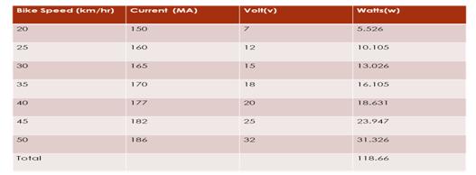
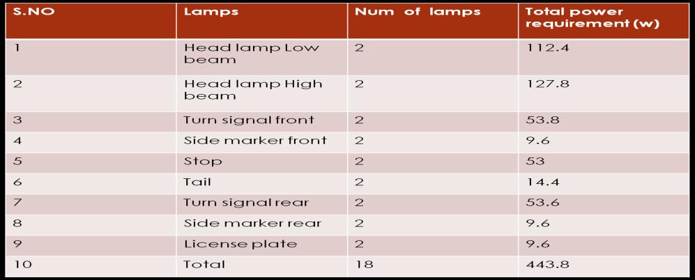
6 TOTAL POWR REQUIREMENT: 101
7 Bike Speed m/s Current ma volt (v) Power(W) CONCLUSION: The work is completed about the theoretical calculation and fabrication work of windenergy. The following results were presented as follows. Mass flow rate of wind and wind force can be calculated. Total power can be calculated by bike speed and power output REFERENCES: [1] Miranda V. Wind power, distributed generation: new challenges, new solutions. Turk J Electro Eng Co 2006; 14: [2] Drusus B, Gogol C. Economic analysis of a wind-battery hybrid system: An application for a house in Gaze, Turkey, with moderate wind energy potential. Turk J Electro Eng Co 2012; 20: 319{333.Computational study on novel circulating aerofoils for use in Magnuswind turbine blades [3]Ahmad Seagate, Iman Samani, Mojtaba Ahmadi-Baloutaki, M. El Haj Assad, Mohamed Gaithc Seifert J. A review of the Magnus effect in aeronautics. Prog Aerosp Sci 2012;55: [4] Reid EG. Tests of rotating cylinders. Flight 1925: [5] Gavalda J, Massons J, Diaz F. Drag and lift coefficients of the Savonius wind machine. Wind Eng 1991;15(5): [6] Ingham DB. Steady flow past a rotating cylinder. Comput Fluids 1983;11(4): [7] Mittal S, Kumar B. Flow past a rotating cylinder. J Fluid Mech 2003;476: