ON SITE ELECTROLITIC PLANT FOR PRODUCTION AND AUTOMATIC DOSING OF SODIUM HYPOCHLORITE
|
|
|
- Cameron Montgomery
- 5 years ago
- Views:
Transcription
1 ON SITE ELECTROLITIC PLANT FOR PRODUCTION AND AUTOMATIC DOSING OF SODIUM HYPOCHLORITE M. Tita St. No. 248b KULA SERBIA Tel/Fax: Web:
2 ABOUT THE COMPANY Sigma was founded in Basic business is production of Hlorogen plants and Automatic Dosing Systems. First Hlorogen plant was produced in and since than it has been constantly improved. Sigma is engaged in engineering, installation and maintenance of on-site automatic systems for disinfection of drinking water. In our offer are also training of workers and remote system monitoring. Our tradition and experience are guaranties for comprehensive service in water disinfection.
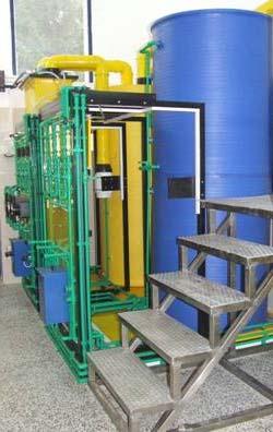
3 WHAT IS HLOROGEN? Hlorogen is device for electrolytic production of chlorine in the form of sodium hypochlorite solution. This production is done on site in absolutely safe way. Since no gaseous chlorine is present, water chlorination is absolutely safe due to system design. For production of sodium hypochlorite solution all that is needed is common salt, softened water and electric energy. Production expenses are up to two times lower compared to gaseous chlorine disinfection, or commercial sodium hypochlorite. The system is easy to use, demands only minimal maintenance and it is fully automated.
4 Plant type HLOROGEN 1000 HLOROGEN PLANT TYPES Capacity (kg/h) 1 Electrolyte Flow (l/h) 100 Current (A) 200 Voltage (V) HLOROGEN HLOROGEN HLOROGEN HLOROGEN HLOROGEN Unlimited capacity Modular Hlorogen Systems are made on request. IN MODULAR CONNECTION WE CAN PRODUCE PLANTS WITH CAPACITI OF 3, 4 OR MORE kg/h 28
5 BASIC OPERATION Water from the pipeline is flows into ion exchange column (4), calcium c and magnesium ions are removed, and on the outlet of the column softened water is obtained. Dosing pump (6) transfers this water to the electrolyzer er where it is mixed with sodium chloride solution transferred from tank (3) by another dosing pump ( tank 3 contains saturated sodium chloride solution). Electrochemical reaction, which results in conversion of sodium chloride into sodium hypochlorite, is taking g place in the electrolyzer cell energized by direct electric current from energetic assembly (35) of the Hlorogen device. Hypochlorite solution is stored in the tank (2).
 into pipeline with water in order of disinfection.")
6 BASIC OPERATION Hydrogen generated by conversion reaction is ventilated in to atmosphere by ventilation system(28). Optimal hypochlorite production is achieved using process control system (36). Sodium hypochlorite solution is injected by membrane dosing pumps(38) into pipeline with water in order of disinfection. Residual chlorine analyzer is connected into regulation circuit with dosing pump and keeps the concentration of residual chlorine in water on the predetermined level. This is providing continuous production of disinfecting agent, automatic a process control and automatic dosing and residual chlorine control. System operation can be monitored through PC (37)

7 COMPONENTS

8 HYDRAULIC BOARD
9 ELECTROL TROLYZER Electrolyzer is the basic, crucial component of Hlorogen device. This component is modular: consists of electrolytic cells connected in series, each cell contains three specially designed cathodes and two Titanium anodes. Precious metal-oxid activated anodes have high ion selectivity and high resistance to corrosion. Several models of the Hlorogen devices are in production using different type of electrolyzer. Capacity range is from 1,2 Kg up to 24 Kg of equivalent chlorine per day. Input solution: : 3% NaCl Chlorine concentration in output solution: : g/l
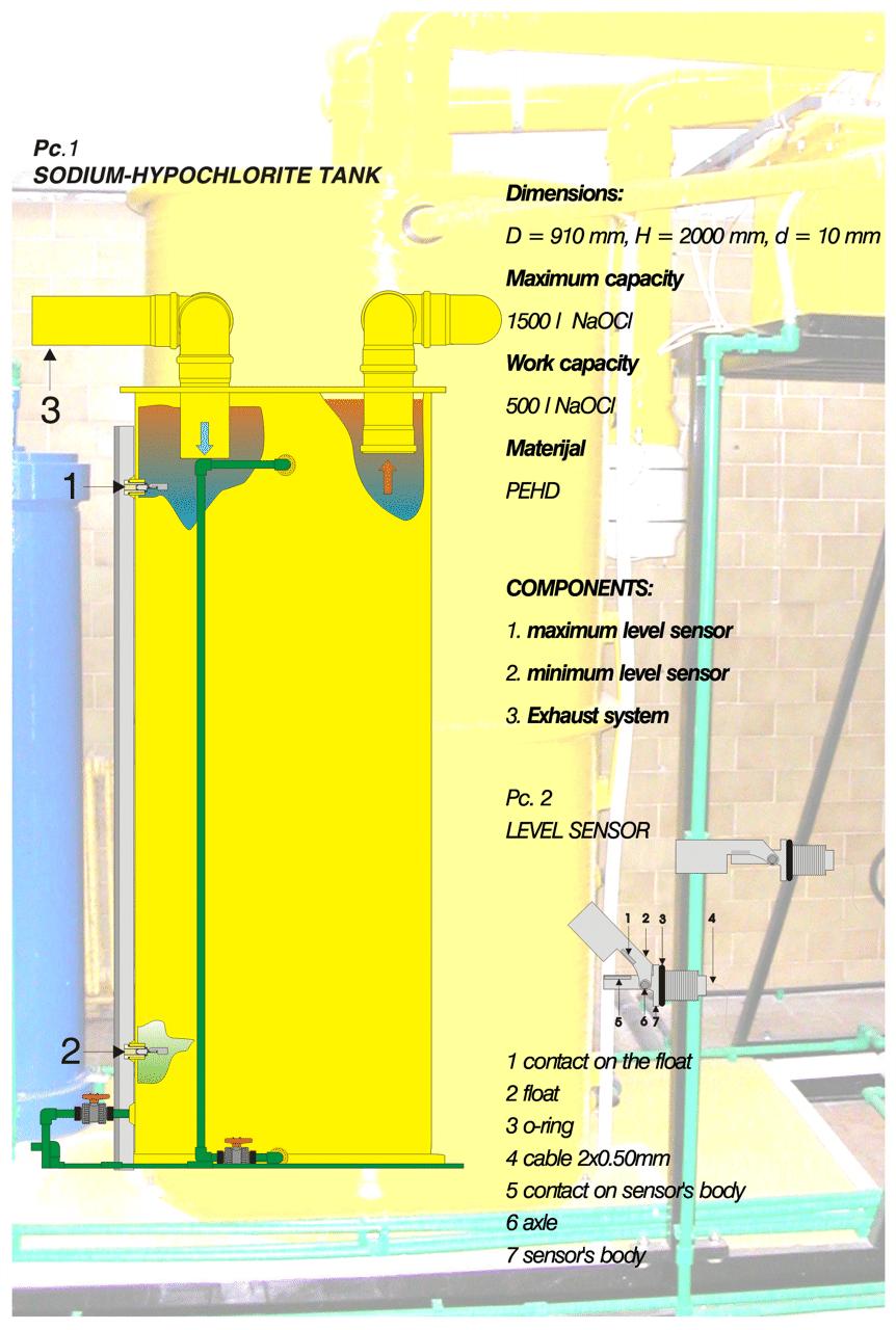
10 SODIUM HYPOCHLORITE TANK
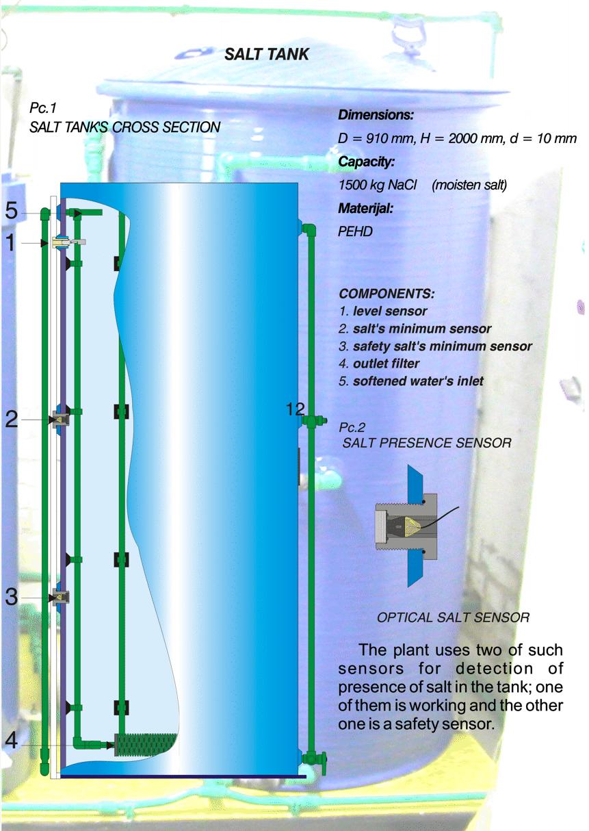
11 SALT TANK

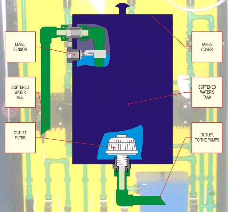
12 SOFTENED WATER TANK

13 WATER SOFTENER

14 SIGMA PUMPS FOR HLOROGEN


15 POWER CABINET Power cabinet s elements, Front view Power cabinet, Rear view

16 HLOROGEN PROCESSOR Processor unit manages and controls production process of sodium hypochlorite, providing communication with other regulation units and PC unit. Letter and numerical display indication of operating stages, values of measured parameters and existence of active alarm situations are also handled by the processor. Communication with PC provide comprehensive control system for the hypochlorite production process. Processor unit includes software for monitoring of technological process. Sending of daily and alarm reports to remote control point is achieved through PC unit connected to intranet or internet.

17 PROCESSOR OR WITH MEASUREMENT INSTRUMENTS
18 OPERATING CYCLES Electrolysis operation cycle of the Hlorogen device is when electrolyzer, all pumps and electromagnetic valves are operating. This cycle last until the upper level of hypochlorite is reached in the hypochlorite tank. Standby operating cycle is when upper level of hypochlorite is reached in the reception tank, causing that electrolyzer, feeding pumps and adequate valves are not in operation. Operation is stopped until the lower level of hypochlorite in the reception tank is reached, and that causes restarting of production process - electrolysis. Regeneration and flushing cycle of ion exchange unit begins after determined hours of electrolysis / production operation. Device is automatically stopped and than regeneration and flushing process of ion exchange unit takes place lasting for few minutes (depending of column capacity). After this process system is switched back on to production cycle.
19 AUTOMATIC DOSING SYSTEMS A D S P 11 / 22 A D S R 11 / 22 KULA M. Tita 248b SERBIA Tel/Fax: sigmaso@eunet.rs
20 WHY ADS? Our quality and problem analysis of drinking water disinfection chlorination, in case where man determines and manually controls chlorine residual in water, has brought conclusion that disinfection hasn't continuous quality because of man s error. To solve this problem we developed an Automatic Dosing System ADS, that completely satisfies all requirements for high quality and reliable drinking water chlorination in all types of waterworks.
21 ADSP CHLORINATION CONTROLLED BY WATER FLOW Chlorination controlled by the water flow is used when biochemical characteristic of the water is stable and only the water flow is changing in time. Usually it s used for Basic chlorination when raw water come from different sources and when the water flow through main pipe is changing.
22 ADSR CHLORINATION CONTROLLED BY RESIDUAL Chlorination controlled by the residual chlorine is used when fluctuations of a water flow are not to big, but biochemical characteristic of the water is changing. Usually it s used for Corrective chlorination. Case when water comes from waterworks, already prepared and treated with chlorine, but it is needed to correct residual because water has fluctuations in its biochemical characteristic. In the small systems, this type of chlorination is used as basic and only type of chlorination.
23 BASIC OPERATION Dosing system consists of operating and reserve pumps which is ensuring continuous dosing of hypochlorite solution. We have systems with 1 operating and 1 reserve pump (11 system), and system with 2 operating and 2 reserve pumps (22 system). If total automation of disinfection process is required, into system is inserted residual chlorine analyzer ADSR, or water flow meter ADSP, that manages the pump operation. By adding adequate number of pumps any waterworks (no matter how large) can have reliable disinfection system.
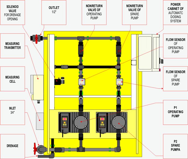
24 ADSP 22 COMPONENTS
25 ADSR 11 COMPONENTS

26 TRANSMITTER AND MEASURING CELL for chlorine residual measure

27 FLOW METER for flow measure
 Power")
28 ADS COMPONENTS SIGMA LOGIC PUMP MTM Metering solenoid diaphragm pump for aggressive media. For dosing disinfectant into the water. Materials: Small PTFE diaphragm; PEHD head and valves; Aluminum housing Control: Pump control unit Capacity: 0 15 l/h (on 5 bar) Power consumption: 220 V AC; 40 W
29 ADS COMPONENTS SIGMA LOGIC PUMP VTM Metering solenoid diaphragm pump for aggressive media. For dosing disinfectant into the water. Materials: Large PTFE diaphragm; PEHD head and valves; Aluminum housing Control: Pump control unit Capacity: 0 30 l/h (on 2.5 bar) Power consumption: 220 V AC; 40 W

30 PC COMPUTER WITH SOFTWARE FOR TRACKING AND CONTROL
31 COMPARATIVE DISPLAY OF DESINFECTION EQUIPMENT BEFORE AND AFTER INSTALLATION OF HLOROGEN PLANT


32 BEFORE AFTER Gaseous chlorination Hlorogen and ADS JKP VODOVOD SMEDEREVO


33 BEFORE AFTER Gaseous chlorination Hlorogen and ADS JKP VODOVOD SREMSKA MITROVICA


34 BEFORE AFTER Gaseous chlorination Hlorogen and ADS JKP Beogradski Vodovod CS Ripanj

35 For now, we have 83 installed HLOROGEN systems 95 automatic dosing systems 30 manual dosing systems On 81 sites in 58 different places in Serbia.


36 IM CARNEX VRBAS year installed system. Capacity of 250 g of chlorine per hour.


37 JKP USLUGA ODŽACI 2. system installed on Decemberer Capacity of 1000 g of chlorine per hour.


38 JKP Beogradski vodovod December Two systems packed in containers. Capacity of 50 g of chlorine per hour.


39 JKP VODOVOD SMEDEREVO August installed system. Capacity of 1000 g of chlorine per hour.


40 JKP VODOVOD VLASOTINCE September installed system. Capacity of 1000 g of chlorine per hour.


41 JKP VODOVOD SREMSKA MITROVICA May installed system. Capacity of 2000 g of chlorine per hour.


42 JKP VODOVOD i KANALIZACIJA NOVI SAD PS SREBRO installed system in container September Capacity of 125 g of chlorine per hour.

43 Sigma and HLOROGEN are ISO 9001:2008 certified
44 Sigma holds patent for procedure of cholirination of water