CUYAHOGA COUNTY ENGINEER
|
|
|
- Tyrone Black
- 5 years ago
- Views:
Transcription

1 CUYAHOGA COUNTY ENGINEER DRAINAGE MANUAL Supplement to O.D.O.T. LOCATION and DESIGN MANUAL, Volume 2, Drainage Design, Section 1000 and 1100 May 28, 2010 Revisions to the July 29, 2009 edition are noted by a vertical line in the right page margin.
2 INTRODUCTION Volume Two, Sections 1000 and 1100 of the O.D.O.T. Location and Design Manual, except as modified herein, together with this supplement, shall be applicable to all Cuyahoga County funded County Road or Bridge improvement projects. It is the objective of this manual to supplement O.D.O.T. drainage policy and also to indicate the differences between Cuyahoga County policy and O.D.O.T. policy. In order to facilitate crossreferencing, the topic headings and section numbers used in this manual correspond to those in the Location and Design Manual. Where references are made to the State, the Administrator/Office of Structural Engineering (Hydraulic Section), or any other term designating any representative or employee of the State, or the Department of Transportation, as found in Sections 1000 and 1100 of the O.D.O.T. Location and Design Manual, such references shall alternately mean Cuyahoga County, Cuyahoga County Chief Highway Design Engineer and the Cuyahoga County Chief Bridge Design Engineer. When a municipality has a written drainage policy, which the municipality desires to apply to a county funded County Road or Bridge improvement project, the Chief Highway Design Engineer or Chief Bridge Design Engineer shall review the municipality's policy and determine if such policy is appropriate for use on the project. CCE Drainage Manual Page 1
3 TABLE OF CONTENTS SECTION REVISION NUMBER SUBJECT DATE PAGE 1001 Cuyahoga County Hydraulic Design Policy 02/01/ Cuyahoga County Pipe Policy 09/26/ Hydrology 02/01/ Flood Clearance 05/22/ Culvert Allowable Headwater 02/01/ Subsurface Pavement Drainage 05/28/ Estimating Design Discharge 09/26/ Open Water Carriers 08/27/ Pavement Drainage 08/27/ Storm Sewers 08/27/ Roadway Culverts 09/26/ Longitudinal Sewer Location 09/26/ Sanitary Sewers 05/22/ CCE Drainage Manual Page 2
4 TABLE OF CONTENTS (Cont.) REVISION SUBJECT DATE PAGE Supplements to Appendix A and Drainage Design Aids 15 3C Catch Basin Bypass Charts 05/22/ Cross Slope = 3/16" per foot 16 Cross Slope = 1/4" per foot 17 Cross Slope = 5/16" per foot 18 Cross Slope = 3/8" per foot 19 Cross Slope = 7/16" per foot 20 Cross Slope = 1/2" per foot 21 Cross Slope = 3/4" per foot 22 Cross Slope = 1" per foot 23 No. 3C Catch Basin Spacing Form Instructions 02/01/ No. 3C Catch Basin Spacing Form (English Units) 06/01/ No. 3C Catch Basin Spacing Form (Metric Units) 06/01/ Cuyahoga County Storm Sewer Computation Form Instructions 02/01/ Cuyahoga County Storm Sewer Computation Form (English Units) 06/01/ Cuyahoga County Storm Sewer Computation Form (Metric Units) 06/01/ Cuyahoga County Culvert Calculation Form (English Units) 06/01/ Cuyahoga County Culvert Calculation Form (Metric Units) 06/01/ CCE Drainage Manual Page 3
5 (1001) CUYAHOGA COUNTY HYDRAULIC DESIGN POLICY Responsibilities Depending on which Department manages the project, the Cuyahoga County Chief Highway Design Engineer or the Cuyahoga County Bridge Design Engineer is responsible for the hydraulic and structural design approval of all prefabricated structures having a span of less than twenty feet (6.1 meters) and all standard headwalls or endwalls used in conjunction with these structures. The Cuyahoga County Chief Bridge Design Engineer is responsible for the hydraulic and structural design approval of all prefabricated structures having a span of twenty feet (6.1 meters) or greater and all headwalls or endwalls used in conjunction with these structures. He also is responsible for the structural design approval of all non-standard headwalls or endwalls used in conjunction with prefabricated structures having a span of less than twenty feet (6.1 meters). The Cuyahoga County Chief Bridge Design Engineer is responsible for the structural design approval of all cast-in-place structures regardless of structure size and for the hydraulic design approval of cast-in-place structures having a span of twenty feet (6.1 meters) or greater. Depending on which Department manages the project, the Cuyahoga County Chief Highway Design Engineer or the Cuyahoga County Bridge Design Engineer is responsible for the hydraulic design approval for cast-in-place structures having a span of less than twenty feet (6.1 meters) Natural Streams Channel designs and channel relocations of all natural streams passing through a proposed highway facility are the responsibility of the Chief Engineer (Bridge or Highway Design) who is responsible for the hydraulic review and approval for the highway structure. CCE Drainage Manual Page 4
6 (1002) CUYAHOGA COUNTY PIPE POLICY Conduit Types Type A Conduits Non-reinforced concrete pipe and clay pipe shall not be specified as Type A conduit. Subject to the approval of the maintaining agency, all other pipe materials listed under (Type A Conduits) are acceptable. Specify Class III minimum for and Class HE-III minimum for Any special designs using alternate materials must be pre-approved by the County as well as the maintaining agency Type B Conduits Subject to the approval of the maintaining agency, all pipe materials listed under (Type B Conduits) are acceptable. Specify Class III minimum for and Class HE-III minimum for Specify Class 3 for Maximum allowable size 21 (525 mm). Specify Extra Strength (ES) for Maximum allowable size 15 (375 mm). Provide joints for all concrete pipe (706.01, , and ). Provide joints for all clay pipe ( ES) Type C Conduits Subject to the approval of the maintaining agency, all pipe materials listed under (Type C Conduits) are acceptable. Specify Class 3 for Maximum allowable size 21 (525 mm). Specify Extra Strength (ES) for Maximum allowable size 15 (375 mm). Provide joints for all concrete pipe (706.01, , and ). Provide joints for all clay pipe ( ES) Type D Conduits Subject to the approval of the maintaining agency, all pipe materials listed under (Type D Conduits) are acceptable Type E Conduits Where used, all pipe materials listed under (Type E Conduits) are acceptable subject to approval of the maintaining agency Type F Conduits Subject to the approval of the maintaining agency, all pipe materials listed under (Type F Conduits) are acceptable. CCE Drainage Manual Page 5
7 B. Type F non-perforated underdrain outlet pipe material shall be the same as or compatible with the actually installed perforated underdrain pipe material. Subject to approval of the maintaining agency, all pipe materials listed under Type F Conduits (underdrain outlets) are acceptable. (1003) HYDROLOGY Estimation of Magnitude and Frequency of Floods on Ohio Streams Limitations The design discharges from drainage areas in excess of six and a half (6.5) square miles (16.8 km 2 ) shall be calculated using USGS Report regardless of the basin characteristics (rural or urban) Design Year Frequency (1004) FLOOD CLEARANCE County Roads (2000 ADT and Over) County Roads (Under 2000 ADT) 25-Year 10-Year (1006) CULVERT ALLOWABLE HEADWATER Design Storm As stated in Section of this supplement Controls Design Storm Controls A. Two (2) feet (0.6 meter) below the tree lawn grade break (berm) elevation typically located at the right-of-way for a curbed pavement. One (1) foot (0.3 meter) below the outer edge of graded shoulder (berm) elevation for an uncurbed pavement Types of Subsurface Drainage Pipe Underdrains (1009) SUBSURFACE PAVEMENT DRAINAGE For County Roads, typically provide a single row of pipe underdrains on each side of the pavement regardless of the pavement width. CCE Drainage Manual Page 6
8 The size of all underdrain pipe shall be six (6) inch (150mm) diameter unless project conditions make it necessary to specify four (4) inch (100mm) diameter. For new construction, four (4) inch (100mm) size underdrain may only be used upon approval of the Chief Highway Design Engineer and the maintaining agency. All underdrain shall be of the size specified in the plan/proposal even when the kind of pipe material is not specifically itemized. Subject to the approval of the maintaining agency, the following six (6) inch (150mm) perforated pipe material may be used: , , , , , (Perforated per ) and (Perforated per ). Subject to the approval of the maintaining agency, the following four (4) inch (100mm) perforated pipe material may be used when permitted as specified above: , , , , (Perforated per ) and (Perforated per ). Nonwoven or Monofiliment woven filter fabric wrap per shall be specified except when spot (contingency) replacement is called for. Where available outlets permit, a desirable underdrain depth of 30 inches (750mm) below subgrade should be specified. Minimum depths of 18 inches (450mm) below subgrade are acceptable. An absolute minimum depth of twelve (12) inches (300mm) below subgrade may be permitted for rock cut installations or where warranted for special design conditions. Designer Note: Reference is made to the Cuyahoga County Engineer's General Plan Note No. CUY- D13, Item 605 Shallow (Base) Pipe Underdrains With Fabric Wrap, As Per Plan Procedures Statistical Methods (1101) ESTIMATING DESIGN DISCHARGE In addition, the SCS Method (TR-20) may be used, if approved by the County's Chief Bridge/Highway Design Engineer Rainfall Intensity Note: Figure , Area A is used for Cuyahoga County. CCE Drainage Manual Page 7
9 (1102) OPEN WATER CARRIERS Ditch Design Criteria for County Roads over 2000 ADT Design Frequency For roadside ditches, whose primary function is pavement drainage, a 2-year frequency storm shall be used to determine the ditch depth, velocity of flow and depth of ditch lining. The design frequency criteria for all other ditches shall be as stated. The depth of flow for any roadside ditch shall be limited to the elevation of the outside edge of the pavement shoulder. All other ditches shall not be overtopped for the design discharge Estimating Design Discharge Runoff will be estimated by the Rational Method for all ditches. The drainage area contributing to roadside ditches, whose primary function is pavement drainage, shall be determined per Section of this supplement. The drainage area contributing to all other ditches shall be determined based upon topographic mapping and site observation as required. Drive pipe conduit types shall be in accordance with Section of this supplement. The headwater shall not exceed the limits in Section of this supplement Ditch Protection Velocity protection shall be in accordance with except that a 2-year frequency event shall be used for roadside ditches as defined in above Ditch Design Criteria for County Roads less than 2000 ADT Design Frequency As stated in Section of this supplement. CCE Drainage Manual Page 8
10 Estimating Design Discharge As stated in Section of this supplement Sheer Stress Protection In accordance with above, a 2-year frequency event shall be used for roadside ditches. A 5-year frequency event shall be used for all other ditches General (1103) PAVEMENT DRAINAGE The following are acceptable catch basins and inlets for curbed Cuyahoga County roads: (a) (b) (c) (d) (e) Cuyahoga County No. CB-3C. Cuyahoga County No. CB-3C2 (twin 3C). Subject to Municipal Engineer approval, O.D.O.T. Pavement Inlets; No. 2A-6 (1.8m), No. 2A-8 (2.4m), and No. 2A-10 (3.0m). O.D.O.T. CB, No. 6 (for use with mountable curbs and/or at drives should catch basin locations at drives be necessary). Others may be considered upon request or approval of the maintaining agency Design Frequency A 2-year design frequency shall be used for all County Roads. Pavement inlets or catch basins shall be spaced to limit the spread of flow such that a minimum of 4 feet (1.2 meters) of "dry" pavement remains in the curb lane. The spread check for 25-year or 50-year storms for underpasses or other depressed roadways is NOT required Estimating Design Discharge Runoff will be estimated by the Rational Method. The drainage area contributing to the pavement shall be generally considered as 150 feet (45 meters) taken on each side of the roadway centerline, except as follows: CCE Drainage Manual Page 9
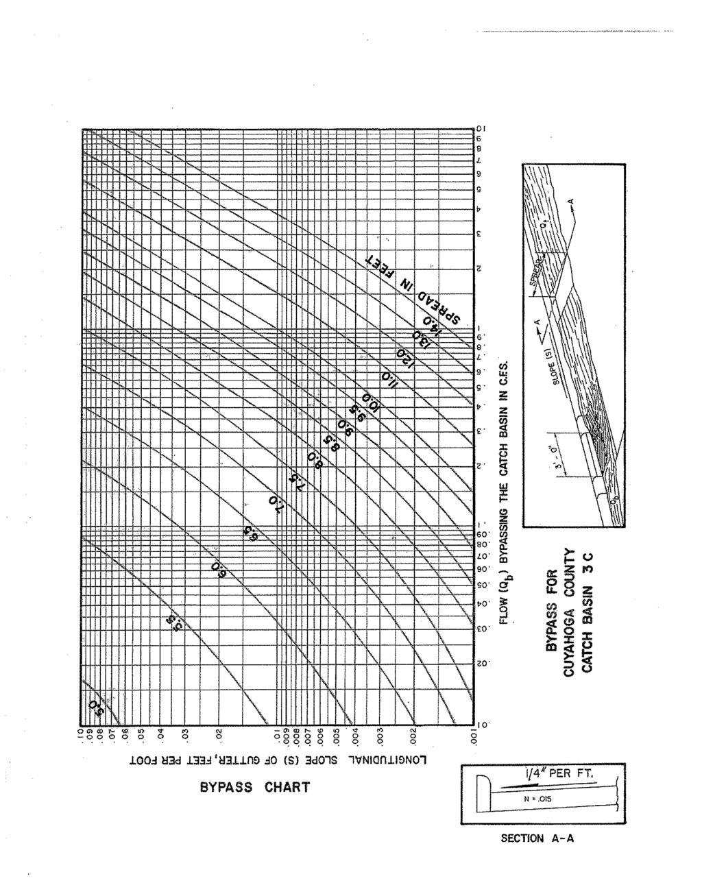
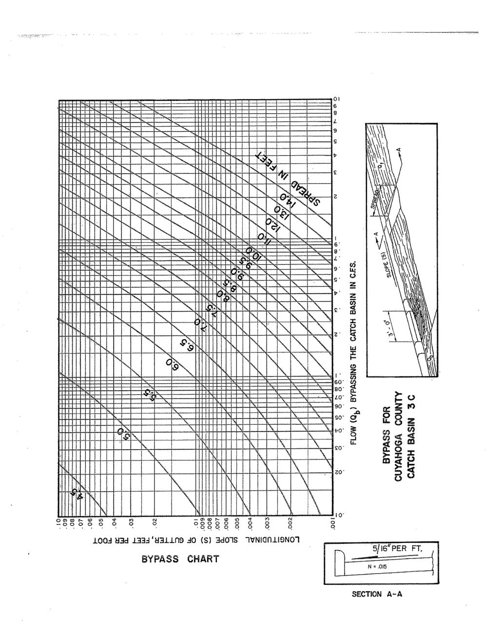
11 (a) (b) (c) In fill areas where it is evident that there will be no future development, the contributing area shall be the area of the roadway cross section that drains toward the pavement. In highly developed or urbanized areas the actual area draining to the pavement may be used in lieu of the 150 foot (45 meter) strip, provided the actual area can be clearly determined from topographic maps and site inspection. Where the overland slope beyond the right-of-way is away from the roadway, but where it is likely that future development will cause portions of this area to slope towards the pavement, the contributing area shall be based on the designer's judgment. Generally the 150 foot (45 meter) strip shall not be exceeded nor shall a strip less than the right-of-way width be used. For contributing areas of 150 feet (45 meter) or less each side of the pavement centerline, the design storm shall be calculated using a rainfall duration of 15 minutes with an intensity of 2.95 inches/hour (75mm/hour) for the 2-year storm. In existing commercial areas with mostly paved frontage, the duration time may be 10 minutes. In the rare event the 150 foot (45 meter) strip is exceeded, the actual time of concentration shall be used to determine the rainfall intensity assuming it is more than the 15 minute/10 minute durations prescribed above Bypass Charts for Continuous Pavement Grades Companion bypass charts for Cuyahoga County 3-C catch basins on various pavement cross slopes are included in the "Supplements to Appendix A and the Drainage Design Aids". The Designer should note that the bypass charts as noted above take into account the local two (2) inch (50mm) pavement depression as detailed on Cuyahoga County Construction Drawing No. CB-3C. For metric units, use the English unit bypass charts and convert the resultant answers into metric units by using the following conversions: Given: To Get: English Units Multiply By Metric Units Feet Meters (m) Inches Per Foot (in./ft.) 1/12 (decimal slope rate): (m/m) Feet Per Foot (ft./ft.) 1.0 (decimal slope rate): (m/m) Cubic Feet Per Second (cfs) Cubic Meters Per Second (m 3 /s) CCE Drainage Manual Page 10
12 Grate Catch Basins in Pavement Sags Cuyahoga County No. CB-3C2 (twin 3C) catch basins shall be provided at the low points of sag vertical curves. The 2-year design frequency spread of flow at the low point shall be limited per Section of this supplement. The next upstream Cuyahoga County No. CB-3C catch basins on each side of the low point shall be located to limit the flow reaching the sag catch basins such that the spread requirements are not exceeded. Conservatively assuming the capacity of the Cuyahoga County No. CB-3C2 (twin 3C) catch basin to be equivalent to the State's standard No. CB-3 catch basin, the standard CB-3 capacity curves in Figures and of the Location and Design Manual may be used to determine the depth of ponding at the lowpoint. Evaluating the spread for a 25-year or 50-year event in a depressed sag is NOT necessary. It should be noted that although the depth of ponding based on grate capacity can be used to determine the 25-year or 50-year event spread, the hydraulic grade line is more of a controlling factor at low points of sag vertical curves. The hydraulic grade line requirement as explained in section of this supplement should be checked for a 50 yr. storm at the low points Data Presentation Appropriate computer software may be used provided that all the information ordinarily furnished in the "No. 3C Catch Basin Spacing Form" is clearly presented for review by the County Highway Design Department personnel General As stated and as supplemented herein. (1104) STORM SEWERS The drainage area contributing to the storm sewer system shall be determined from topographic mapping supplemented by: (a) (b) Field Observation. Data from the Municipal Engineer such as municipal sewer maps which may indicate contributary sewers from side streets, subdivisions or commercial developments. In no case shall the drainage area be less than the highway right-of-way. CCE Drainage Manual Page 11
13 When the local governmental agency, through whose jurisdiction the highway improvement passes, desires that runoff from areas in addition to those naturally contributing to the roadway storm sewer be included in the roadway storm sewer system, the Agreement for the improvement between the Board of County Commissioners and the local agency must contain provisions for the increase in contributary area Design Considerations Storm Sewer Depth (J) Where outfall conditions permit, depths shall be such that structure footer drains can outlet to the storm sewer by gravity flow. (K) When applicable, storm sewers shall be at least as deep as those they replace to ensure an outlet for existing lateral connections. Where proposed highway storm sewers or ditches will interfere with existing private drains carrying treated sanitary flow, the designer must obtain a list of all property owners authorized to discharge treated sanitary effluent into the storm sewer/ditch system. This information including residential septic system site plans may be obtained from the County Board of Health and/or the City/Village Engineer Storm Sewer Design Criteria Hydraulic Grade Line As stated in the O.D.O.T. Location and Design Manual except that the resultant ponding based on the 50-year check shall be limited to the top of curb. The friction slope (S f ) for conduits flowing under pressure may be determined by the following equation: (English Units) (Metric Units) S f = 4.66n 2 xq 2 /D 16/3 S f = 10.29n 2 Q 2 /D 16/3 Q (cfs) = Q 25 Q (m 3 /s) = Q 25 D = conduit diameter (feet) D = conduit diameter (meters) CCE Drainage Manual Page 12
14 Time of Concentration t c = 15 min. to first ditch inlet/pavement catch basin or 10 min. for mostly paved commercial frontages. If the distance from the most remote point of the drainage area to the first inlet exceeds 150 feet (45 meters), use the actual time of concentration assuming it is more than the 15 minute/10 minute durations prescribed above Hydraulic Design Procedure As stated except that appropriate computer software may be used provided that the hydraulic calculation data ordinarily furnished on the "Cuyahoga County Storm Sewer Computation Form" is clearly presented for review by County Highway Design Department personnel Design Procedure General (1105) ROADWAY CULVERTS S.C.S. Method (TR-20) may be used within limitations, if approved by the County Chief Highway/Bridge Design Engineer Hydraulic Analysis As stated except that the required hydraulic analysis/calculation data ordinarily provided on the "Cuyahoga County Culvert Calculation Form" shall be clearly presented for review by County Bridge/Highway Design Department personnel Under County Road Pavement (1109) LONGITUDINAL SEWER LOCATION The designer shall make every reasonable attempt to locate longitudinal sewers so that they are not under the pavement. Preferably, the storm sewer will be on the opposite side of the roadway from the sanitary sewer. A minimum of six (6) feet (1.8 meters) clear distance between storm and sanitary sewers should be maintained. Where this clearance cannot be obtained, all portions of both the longitudinal storm and sanitary sewers, excluding minor crossings; shall be constructed using premium jointed conduit for their full (manhole to manhole) runs. Manholes should not be located in the pavement or sidewalk unless no practical alternative exists. CCE Drainage Manual Page 13
15 (1111) SANITARY SEWERS General Sanitary sewers which are under the jurisdiction of the County Sanitary Engineer shall be designed in accordance with policies and criteria of the Cuyahoga County Sanitary Engineer. Sanitary sewers which are under the jurisdiction of the local municipality shall be designed in accordance with the policies and criteria of the local municipality. O.D.O.T. Directive No. 22-A does not apply to Cuyahoga County roads. CCE Drainage Manual Page 14
16 SUPPLEMENTS TO APPENDIX A AND THE DRAINAGE DESIGN AIDS SUBJECT PAGE No. 3C Catch Basin Bypass Charts Cross Slope = 3/16" per foot 16 Cross Slope = 1/4" per foot 17 Cross Slope = 5/16" per foot 18 Cross Slope = 3/8" per foot 19 Cross Slope = 7/16" per foot 20 Cross Slope = 1/2" per foot 21 Cross Slope = 3/4" per foot 22 Cross Slope = 1" per foot 23 No. 3C Catch Basin Spacing Form Instructions 24 No. 3C Catch Basin Spacing Form (English Units) 25 No. 3C Catch Basin Spacing Form (Metric Units) 26 Cuyahoga County Storm Sewer Computation Form Instructions Cuyahoga County Storm Sewer Computation Form (English Units) 29 Cuyahoga County Storm Sewer Computation Form (Metric Units) 30 Cuyahoga County Culvert Calculation Form (English Units) 31 Cuyahoga County Culvert Calculation Form (Metric Units) 32 CCE Drainage Manual Page 15
17
18
19
20
21
22
23
24 CUYAHOGA COUNTY NO. 3C CATCH BASIN SPACING FORM INSTRUCTIONS Column 1 Column 2 Column 3 Column 4 Column 5 Column 6 Column 7 Column 8 Column 9 Column 10 Column 11 Column 12 Column 13 Column 14 Reference Number Station of inlet structure. Directional location of inlet structure. Runoff coefficient (See Section of the O.D.O.T. Location and Design Manual). Average Rainfall Intensity in inches per hour (millimeters per hour). Contributory drainage area in acres (hectares). Calculated inflow in cubic feet per second (cubic meters per second). Bypassed flow from adjacent upstream inlet. Total flow into inlet in cubic feet per second (cubic meters per second). Longitudinal slope, assumed parallel to centerline profile. Cross slope of pavement (from typical section). From Pavement Flow Charts (O.D.O.T. Location and Design Manual or Manning's Equation). Gutter flow depth equals Column 11 x Column 12. From attached bypass charts for Cuyahoga County No. 3C Catch Basins. If O.D.O.T. structure is otherwise used, from O.D.O.T. Location and Design Manual, Figures thru A. CCE Drainage Manual Page 24
25
26
27
28
29
30
31