SUBSURFACE INVESTIGATION
|
|
|
- Daniela Clark
- 5 years ago
- Views:
Transcription
 (S) STATE HIGHWAY 412 SECTION 7 & 8 IN LAWRENCE & GREENE COUNTY The information contained herein was obtained by the Department for design and estimating purposes only.")
1 ARKANSAS DEPARTMENT OF TRANSPORTATION SUBSURFACE INVESTIGATION STATE JOB NO. CA03 FEDERAL AID PROJECT NO HWY. 67 HWY. 141 (WIDENING) (S) STATE HIGHWAY 412 SECTION 7 & 8 IN LAWRENCE & GREENE COUNTY The information contained herein was obtained by the Department for design and estimating purposes only. It is being furnished with the express understanding that said information does not constitute a part of the Proposal or Contract and represents only the best knowledge of the Department as to the location, character and depth of the materials encountered. The information is only included and made available so that bidders may have access to subsurface information obtained by the Department and is not intended to be a substitute for personal investigation, interpretation and judgment of the bidder. The bidder should be cognizant of the possibility that conditions affecting the cost and/or quantities of work to be performed may differ from those indicated herein.
2 Geotechnical Engineering Report Revision 1 AHTD Job No. CA 03 Highway 412 Light Bypass Highway 67 Highway 141 (Widening) (S) FAP NO.9991 Lawrence and Greene Counties, Arkansas January 24, 2018 Terracon Project No Prepared for: Prepared by: Terracon Consultants, Inc. Little Rock, Arkansas
3
4 TABLE OF CONTENTS Page 2.1 Project Description Site Location and Description Geology Typical Profile Groundwater Bypass Subgrade Soil Geotechnical Considerations Earthwork... 6 Site Preparation... 6 Import Material Specifications... 7 Compaction Requirements... 8 Lime Treated Subgrade... 9 Excavation and Trench Construction... Utility Trench Backfill Subgrade Preparation APPENDIX A FIELD EXPLORATION Exhibit A-1 Site Location Plan Exhibits A-2 to A-4 Exploration Plans Exhibit A- Field Exploration Description Exhibits A-6 to A-22 Boring Logs APPENDIX B TESTING Exhibit B-1 Laboratory Testing Description Exhibit B-2 to B- Grain Size Distribution Additional Laboratory Data Laboratory Compaction Characteristics of Soil Resilient Modulus Testing APPENDIX C SUPPORTING DOCUMENTS Exhibit C-1 Explanation of Boring Log Information Exhibit C-2 Unified Soil Classification System Exhibit C-3 AASHTO Soil Classification System Responsive Resourceful Reliable
5 GEOTECHNICAL ENGINEERING REPORT, REVISION 1 AHTD JOB NO. CA 03, HIGHWAY 67 HIGHWAY 141 (WIDENING) (S) HIGHWAY 412 LIGHT BYPASS LAWRENCE AND GREENE COUNTIES, ARKANSAS Terracon Project No January 24, 2018 INTRODUCTION This report presents the results of the geotechnical engineering services performed for the AHTD Job No. CA 03 Light Bypass along Highway 412 in Lawrence and Greene Counties, Arkansas. Terracon prepared a Shoulder Survey Report, dated September 26, 2016, for the Highway 412 alignment, excluding the Light Bypass section. Seventeen exploratory borings extending to depths of approximately 4 to 40 feet below existing ground surface were drilled in the planned Light Bypass alignment for this report. The boring logs, site plan and boring location plan are presented in the Appendix. PROJECT INFORMATION 2.1 Project Description Site layout Structures Item See Appendix A Site Location Plan, Exhibit A-1 Description Boring Location Plans, Exhibits A-2 through A-4 We understand the overall project involves widening about 14.4 miles of Highway 412 between Highway 67 and Highway 141 in Lawrence and Greene Counties, Arkansas. The Light Bypass, for which this report was prepared, will involve constructing a new four-lane highway (two lanes each direction) to the south of the existing Highway 412 alignment. Construction will include: new asphaltic concrete pavement new drainage culverts culverts Responsive Resourceful Reliable 1
6 Geotechnical Engineering Report, Revision 1 AHTD Job No. CA03, Lawrence and Greene Counties, Arkansas January 24, 2018 Terracon Project No Site Location and Description Item Location Existing improvements Grading Description See Appendix A, Exhibit A-1, Site Location Plan Approximately between Sta and Sta Approximately 2.8 miles in Greene County, Arkansas. Two-lane Highway 412 at east and west ends of proposed bypass. The existing pavement is asphaltic concrete with paved shoulder on both sides of the highway. The bypass route is farmland, with ground cover of exposed soil, agricultural crops or grass, and a few relatively small areas of tree growth. Arkansas Highway 228 and a few unpaved farm roads cross the bypass route. Based on the Final Plans and Profiles, the Light Bypass will require engineered fill to raise the grade above the floodplain. We estimate maximum cuts and fills of about 7 feet and 13 feet, respectively, based on the Final Plans. Final slopes are designed at or less than 3H:1V, typically at 3H:1V and 6H:1V Responsive Resourceful Reliable 2
7 Geotechnical Engineering Report, Revision 1 AHTD Job No. CA03, Lawrence and Greene Counties, Arkansas January 24, 2018 Terracon Project No SUBSURFACE CONDITIONS 3.1 Geology Terrace Deposits Formation 1 Description 2 Quaternary Period Pleistocene Epoch Dune Sand Quaternary Period Pleistocene Epoch The terrace deposits include a complex sequence of unconsolidated gravels, sandy gravels, sands, silty sands, silts, clayey silts, and clays. The individual deposits are often lenticular and discontinuous. At least three terrace levels are recognized with the lowest being the youngest. Fossils are rare. The lower contact is unconformable and the thickness is variable. The sand dunes generally consist of homogeneous, massive, well-sorted, tan or buff to grayish- or reddish-brown, fine sands. Cross-stratification and bedding features are lacking in the interval, apparently due to extensive weathering and biogenic reworking. These sands are thought to be derived from glacial outwash originally deposited along major drainages during the initial stages of interglacial times. The dunes are best developed on the east sides of the White, Current, and Black Rivers. The dune sand fines with distance from these rivers. Dunes are present on all terrace levels, but not on present-day alluvium. No significant fossils have been discovered associated with these sands. The lower contact seems to be unconformable in most places. 1. Geologic Map of Arkansas, published by the United States Geological Survey, Stratigraphic Summary of Arkansas, published by the Arkansas Geological Commission, Based on the information published in the USDA Natural Resources Conservation Service Soil Survey of Greene County, Arkansas the site can be broadly divided into three soil map units. Greene County Foley-Bonn Complex This complex is typically found along stream terraces. The surface layer is comprised of dark grayish brown silt loam about 3 inches thick. Gray silt loam with iron accumulations underlie the surface layer and measures about 11 inches thick. From 14 to 23 inches, gray silty clay loam and light brownish gray silt loam is found. Gray silty clay loam with iron accumulations underlie this layer and is typically found between 23 to 37 inches. Finally at 37 to 72 inches lies grayish brown silt loam with iron accumulations. Forestdale Silty Clay Loam This soil consists of poorly drained soils that formed in the stratified beds of loamy and clayey alluvium. It is found on old natural levees. The surface layer is dark grayish-brown to light brownish-gray silt loam, 4 to 7 inches thick. The subsoil is Responsive Resourceful Reliable 3
8 Geotechnical Engineering Report, Revision 1 AHTD Job No. CA03, Lawrence and Greene Counties, Arkansas January 24, 2018 Terracon Project No gray or grayish-brown silty clay underlain by gray or light brownish-gray loam to sand. It has slow permeability and moderate water capacity. Wiville Fine Sandy Loam - The Wiville series consists of very deep, well drained, moderately permeable soils that formed in eolian deposits. In a representative profile the surface layer consists of inches of dark yellowish brown fine sandy loam. From to 11 inches; dark yellowish brown fine sandy loam. Underlying this layer, from 11 to 18 inches is brown fine sandy loam. Brown fine sandy loam is found at 18 to 27 inches. Beneath this layer from 27 to 6 inches brown sandy clay loam with a blocky structure is observed. From 6 to 64 inches dark yellowish brown fine sandy loam can be seen. Finally the underlying material consists of yellowish brown fine sand at a depth of 72 inches or more. The soil map units described in this section were obtained by locating the subject site on available large-scale soil survey maps. Due to the scales involved, precise location of the borings on the mapped soil units can be difficult to determine. In addition, the large scale soil survey maps describe only general trends. Local variations are possible and site-specific soil conditions may differ from those described above. A site-specific detailed soil survey was not included in our scope of work for this project. 3.2 Typical Profile Based on the results of the borings, subsurface conditions at the pavement borings are comprised of silty clays, lean clay with varying amounts of sand, fat clays, clayey sands, silt, silty sands and poorly graded sands with variable amounts of clay. Conditions and details observed at the boring locations are indicated on the boring logs included in Appendix A. Stratification boundaries on the boring logs represent the approximate location of changes in soil types; in-situ, the transition between materials may be gradual. Atterberg limits (liquid limit and plastic limit) tests were performed on selected samples of cohesive native soils. The tested native soils were classified as having low to high plasticity with liquid limits ranging between 21 and 4 and plasticity indices ranging between 6 and 40. The laboratory test results are shown on the boring logs in Appendix A. A description of the laboratory testing program is provided in Appendix B. 3.3 Groundwater The boreholes were observed while drilling and after completion for the presence and level of groundwater. Groundwater was observed in Borings B-61BP, B-63BP, B-64BP, and B-6BP a depths of about 9 to 13. feet below the existing ground surface while drilling. Groundwater was not observed in the other borings while drilling or at times of about 24 hours after completion. Water level observations in the boreholes can be found on the boring logs included with this report. Responsive Resourceful Reliable 4
9 Geotechnical Engineering Report, Revision 1 AHTD Job No. CA03, Lawrence and Greene Counties, Arkansas January 24, 2018 Terracon Project No Groundwater level fluctuations occur due to seasonal variations in the amount of rainfall, runoff and other factors not evident at the time the borings were performed. Therefore, groundwater levels during construction or at other times in the life of the structures may be higher or lower than indicated on the boring logs. Longer observation in piezometers or observation wells sealed from the influence of surface water are often required to define groundwater levels in these soil types. The possibility of groundwater level fluctuations should be considered when developing the design and construction plans for the project. 3.4 Bypass Subgrade Soil Terracon drilled a total of 17 borings, designated as B-60BP through B-76BP, for this project at the approximate locations shown on the attached boring location plans in Appendix A. The borings were drilled within the proposed bypass right-of-way and spaced approximately 800 feet along the alignment. The boring locations were selected in consultation with the client, and were generally located in the turn rows of existing crop fields. Water content and classification tests were performed on selected soil samples obtained from the borings. Classification, moisture-density relationship (standard Proctor) and resilient modulus tests were performed on the three bulk samples representing the major pedological map units obtained from various locations. The results of these tests are presented in Appendix B. Based on the results of the laboratory testing, the anticipated upper subgrade soils in pavement areas represented by Borings B-60BP through B-68BP have AASHTO classifications predominantly of A-4, while upper soils in areas represented by Borings B-69BP through B-76BP are predominantly A-6 and A-7-6 soils. RECOMMENDATIONS FOR DESIGN AND CONSTRUCTION 4.1 Geotechnical Considerations Based upon the field penetration resistance values, moisture content values and the classification test results, it is our opinion that the native soils or new engineered fill should be able to support new pavements. Low-strength (SPT N-values of blows per foot or less) soils were observed at some of the borings at various depths below the existing ground surface. A summary of the low-strength areas is presented in the following table: Boring Locations Weak Soil Thickness (ft) B-63BP 2 3. B-68BP 8. - B-71BP (below termination depth) Responsive Resourceful Reliable
10 Geotechnical Engineering Report, Revision 1 AHTD Job No. CA03, Lawrence and Greene Counties, Arkansas January 24, 2018 Terracon Project No Additionally, the lean clay and silty lean clay soils encountered at this site are susceptible to strength loss with moisture content increases and when subjected to repeated construction traffic. In their present condition, the low-strength soils are not suitable for supporting new fill or pavements. We expect that ground improvement will be required, and difficult construction conditions will exist during site preparation and grading due to the presence of the near-surface, low-strength soils. Ground improvement alternatives are discussed in Section 4.2 Earthwork. We strongly recommend the geotechnical engineer be retained to evaluate the site conditions during site grading and construction and provide ground improvement recommendations based on the actual conditions. The pavement subgrade soils should be evaluated, tested and improved as necessary as described in this report. Fat clay soils were observed from the surface to a depth of about 2 feet in Boring B-72BP. The fat clays have high plasticity and are subject to shrinking and swelling with variations in moisture content. These shrink/swell movements can be detrimental to pavement surfaces. Although it may not be possible to eliminate all shrink/swell movement of the fat clay soils, we recommend removing the fat clay soils to a minimum depth of 2 feet below finished pavement subgrade elevation and replacing the fat clay soils with a low-volume change, engineered fill to reduce the amount of shrink/swell movement of the subsurface soils. Highway construction for this project should be performed in accordance with applicable sections of the Arkansas Highway and Transportation Department (AHTD) Standard Specification for Highway Construction, 2014 edition. 4.2 Earthwork Earthwork should be performed as required in the AHTD Standard Specifications for Highway Construction, 2014 edition. The following presents general recommendations for site preparation, excavation, subgrade preparation and placement of engineered fills on the project. The evaluation of earthwork should include overexcavation operations, observation and testing of engineered fills, subgrade preparation, and other geotechnical conditions exposed during construction of the project. Site Preparation Where new pavement is planned, all surface vegetation, topsoil, existing pavements, tree roots and stumps and any surface or subsurface structures from previous site use should be removed full-depth. The borings were conducted mainly in agricultural fields that contained disturbed surficial soils within a till zone. We estimated the till zone was about 1 foot thick. Excavations resulting from the removal of any surface or subsurface structures should be cleaned of all loose and disturbed material before placing fill. As previously discussed, surficial fat clay soils were observed to a depth of about 2 feet below the existing ground surface near Boring B-72BP. Where exposed in the pavement subgrade after stripping, we recommend removing and replacing the fat clay soils with new engineered fill to a minimum depth of 2 feet below the Responsive Resourceful Reliable 6
11 Geotechnical Engineering Report, Revision 1 AHTD Job No. CA03, Lawrence and Greene Counties, Arkansas January 24, 2018 Terracon Project No planned finished subgrade elevation. Soils containing organic matter, debris or deleterious matter should not be used as engineered fill. Drainage ditches that are disturbed during construction will need to be drained of any water and mucked out to remove all low-strength soils. All organic and deleterious material should be removed full-depth. Fills placed within the drainage ditch should be benched into the ditch side slopes as the fill placement progresses vertically. The benches should be cut at an equivalent 6H:1V slope. For example, each bench cut 1 foot deep should be at least 6 feet wide. Additionally, the benches should be wide enough for proof-rolling and compaction equipment to sufficiently compact new fill to meet the compaction requirements in Section Compaction Requirements. Areas requiring new fill placement should be initially graded to create a relatively level surface to receive fill and to provide for a relatively uniform thickness of fill beneath the roadway. The exposed subgrade should be proof-rolled with heavy construction equipment such as a loaded tandem-axle dump truck weighing at least 2 tons to aid in locating unstable subgrade materials and prior to placing fills to confirm there are no unstable areas that could prevent proper compaction of additional fills. If unstable areas are noted, the geotechnical engineer should be notified to provide supplemental recommendations. All exposed subgrade areas, once properly cleared and effectively proof-rolled, should be scarified to a maximum depth of 12 inches, conditioned to near optimum moisture content and compacted. Subgrade soils exposed to the elements for an extended period of time should be checked for density and moisture content prior to placing additional fill and/or constructing pavements. During construction of the subgrade, exposed surfaces should be graded to prevent water from ponding adjacent to the existing roadway pavement and on the exposed subgrade. We anticipate excavations for the proposed construction can be accomplished with conventional earthmoving equipment. The stability of subgrade soils may also be affected by precipitation, repetitive construction traffic or other factors. If unstable conditions are encountered or develop during construction, workability can be improved by overexcavating the wet, unstable zones and moisture conditioning and recompacting that soil, or by removing and replacing full-depth with new engineered fill to provide stable subgrade soils. Use of lime could also be considered as a ground improvement treatment technique. Laboratory evaluation is recommended to determine the effect of chemical treatment on subgrade soils prior to construction. The use of lime is further discussed in Section Lime Treated Subgrade. Import Material Specifications Fill materials should be free of organic matter and debris. Clean, on-site soils or approved imported borrow materials may be used as fill material. The fat clay (CH) soils observed at Responsive Resourceful Reliable 7
12 Geotechnical Engineering Report, Revision 1 AHTD Job No. CA03, Lawrence and Greene Counties, Arkansas January 24, 2018 Terracon Project No the Boring B-72BP exhibited a plasticity index value of 40, which is not suitable for use as engineered fill in the upper 2 feet of pavement subgrade. Most of the natural soils observed at the boring locations appear to be suitable for use as engineered fill. If it is desired to use the on-site fat clay soils as engineered fill for this project, we recommend limiting their use to depths greater than 2 feet below finished pavement subgrade elevation. While the AHTD has no specific requirements for borrow materials, they do require that the materials must be capable of forming and maintaining a stable embankment when compacted. Therefore, we recommend specifically avoiding elastic silts (MH) and organic soils (OL, OH and PT) when considering materials for use as borrow. Clay soils should exhibit well-defined moisture-density relationships. We suggest that on-site soils or approved imported borrow soils should meet the following material property requirements: Sieve Size Percent Finer by Weight (ASTM C136) 3 0 No No Plasticity Index..20 (max) Compaction Requirements Engineered fill should be placed and compacted in horizontal lifts, using equipment and procedures that will produce recommended moisture contents and densities throughout the lift. Item Fill maximum lift thickness Compaction requirements 1 Moisture content of cohesive material 1 Moisture content of granular material 2 Description 8 inches or less in loose thickness At least 9 percent of the material s standard Proctor maximum dry density (AASHTO T 99) This density will not be required immediately adjacent to wingwalls of box culverts Within ±2 percentage points of the material s optimum moisture content value as determined by the standard Proctor test (AASHTO T 99) at the time of compaction Workable moisture levels Responsive Resourceful Reliable 8
13 Geotechnical Engineering Report, Revision 1 AHTD Job No. CA03, Lawrence and Greene Counties, Arkansas January 24, 2018 Terracon Project No Item Description 1. We recommend engineered fill be tested for moisture content and compaction during placement (AASHTO T-3 or AHTD Test Method 347 or 348). Should the results of the inplace density tests indicate the specified moisture or compaction limits have not been met, the area represented by the test should be reworked and retested as required until the specified moisture and compaction requirements are achieved. 2. Specifically, moisture levels should be maintained low enough to allow for satisfactory compaction to be achieved without the fill material pumping when proof-rolled. Lime Treated Subgrade Low-strength (SPT N-values of blows per foot or less) soils were encountered at some of the borings at varying depths below the existing ground surface. To improve the subgrade conditions, use of lime could be considered as a treatment technique, as outlined in Section 301 of AHTD Standard Specifications for Highway Construction, 2014 edition. The use of lime treatment is considered only as a ground improvement alternative. The lime-treated subgrade is not considered to be a structural component of the pavement section. The lime should be mixed into the upper 12 inches of the soils exposed at plan finished subgrade elevations. Using this chemical additive, the effectiveness of the chemical treatment will be dependent on 1) the amount of lime used, 2) how thoroughly the lime is mixed into the native soils, and 3) the contractor adhering to time constraints for the mixing and compaction of the soil/lime mixture. The contractor should consider performing a test section to evaluate their proposed process and methods. Based on the exposed soils consisting of lean clays and fat clays, we estimate that 6 to 8 percent lime, by dry weight of soil, will be required to lime-treat the on-site lean to fat clays. The actual amount should be evaluated in accordance with ASTM test method D The lime content determined by this test should be increased by 0. percentage point to allow for construction mixing. Additionally, laboratory evaluation is recommended to determine the effect of chemical treatment on subgrade soils prior to construction. The on-site clay soils could contain soluble sulfate sufficient to adversely react with the lime additive. Soluble sulfate tests run in accordance with TxDOT Test Method TEX 14-E should be performed to confirm soluble sulfate concentrations are less than 3,000 ppm. Lime treatment of the subgrade soils should be completed in accordance with Section 301, Lime Treated Subgrade, Arkansas State Highway and Transportation Department (AHTD) Standard Specifications for Highway Construction, 2014 Edition. The lime additive should be thoroughly mixed into the native soils to a minimum depth of 12 inches below finished subgrade. Mixing of the soils with a rotary-type mixer is recommended to adequately combine the additive into the existing soils. The mixing of the lime with the native soils is time-dependent due to the curing and hydration processes of the lime-treated soil material. A 48-hour hour cure time is recommended from Responsive Resourceful Reliable 9
14 Geotechnical Engineering Report, Revision 1 AHTD Job No. CA03, Lawrence and Greene Counties, Arkansas January 24, 2018 Terracon Project No when the lime is added to the soil, mixed, and compacted to realize the full strengthening properties of the lime-treated subgrade. Construction traffic on the lime-treated soils should be avoided during curing. After curing, the lime-treated subgrade should be protected with a layer of aggregate base for a construction working surface. Per AHTD Standard Specifications, QA/QC testing for lime treated soils shall be in accordance with one (1) test per 12,000 square yards of subgrade area at a minimum depth of 8 inches. Excavation and Trench Construction Excavations into the on-site native soils may encounter caving soils and possibly groundwater, depending upon the final depth of excavation. The individual contractor(s) should be made responsible for designing and constructing stable, temporary excavations as required to maintain stability of both the excavation sides and bottom. All excavations should be sloped or shored in the interest of safety following local and federal regulations, including current OSHA excavation and trench safety standards. Soils penetrated by the proposed excavations may vary significantly across the site. The soil classifications are based solely on the materials observed in the exploratory test borings. The contractor should verify that similar conditions exist throughout the proposed area of excavation. If different subsurface conditions are encountered at the time of construction, the actual conditions should be evaluated to determine any excavation modifications necessary to maintain safe conditions. As a safety measure, it is recommended that spoil piles be kept a minimum lateral distance from the crest of the slope equal to no less than the slope height. The exposed slope face should be protected against the elements. Utility Trench Backfill All trench excavations should be made with sufficient working space to permit construction including backfill placement and compaction. It is strongly recommended that a qualified person provide full-time observation and compaction testing of trench backfill within pavement areas. 4.3 Cut and Fill Slopes We understand that final cut and fill slopes will typically be constructed at a 3H:1V or 6H:1V inclination as shown on the Final Plans. Slopes constructed at a 3H:1V inclination and less than feet high in the types of soils at this site generally exhibit a factor of safety in excess of 1. against short- and long-term global stability. The planned slopes appear to be reasonable for construction. Responsive Resourceful Reliable
15 Geotechnical Engineering Report, Revision 1 AHTD Job No. CA03, Lawrence and Greene Counties, Arkansas January 24, 2018 Terracon Project No Soil slopes should be covered for protection from rain, and surface runoff should be diverted away from the slopes. For erosion protection, a protective cover of grass or other vegetation should be established on permanent soil slopes as soon as possible. PAVEMENTS.1 Pavement Design Resilient modulus testing was performed for each soil map unit identified in the Light Bypass alignment. The resilient modulus testing performed for the Light Bypass pavement subgrade soils yielded similar, slightly higher R-values than the R-values estimated for the pavement subgrade soils for the remaining portion of the Highway 412 widening project (see Terracon s Shoulder Survey Report for results, issued under separate cover). The resilient modulus tests for the three Light Bypass pavement subgrade soils are provided in Appendix B of this report. Based on these test results, the pavement section design alternatives issued on January 12, 2016, for the Highway 412 widening are considered suitable for designing the Light Bypass alignment pavements. No new pavement section design alternatives are provided in this report..2 Pavement Subgrade Preparation Based on the subsurface conditions observed at the boring locations and considering the subgrade is prepared as recommended in Section 4.2 Earthwork, the pavement subgrade materials should consist of tested and approved native soils or new engineered fill. Prior to evaluating the subgrade, all topsoil and vegetation should be removed from the construction area. We recommend the moisture content and density of the top 12 inches of the subgrade be re-evaluated and that it be proof-rolled within two days prior to placing aggregate base. Areas not in compliance with the required ranges of moisture or density should be moisture conditioned and recompacted. Particular attention should be paid to high traffic areas that were rutted and disturbed earlier and to areas where backfilled trenches are located. Areas where unsuitable conditions are located should be repaired by removing and replacing the materials with properly compacted fills..3 Post-Construction Settlement of Pavement Based on the planned grading shown in the Final Plans, the subsurface conditions observed at the boring locations, and by preparing the pavement subgrade per project specifications and this report, we expect that pavement settlement should be within project tolerance requirements. Responsive Resourceful Reliable 11
16 Geotechnical Engineering Report, Revision 1 AHTD Job No. CA03, Lawrence and Greene Counties, Arkansas January 24, 2018 Terracon Project No BOX CULVERT RECOMMENDATIONS 6.1 Structure Descriptions and Locations Location Item Culvert Construction Description See Appendix A, Exhibit A-1, Site Location Plan. Stations 60+29, 64+07, and We understand that three box culverts are planned along the Light Bypass alignment At Station (Boring B-6BP) a triple-cell (7-foot x 4-foot x 128-foot) reinforced concrete box culvert will be installed At Station (Boring B-70BP) a triple-cell (9-foot x 9-foot x 121-foot) reinforced concrete box culvert will be installed At Station (Boring B-76BP) a quad-cell (8-foot x 6-foot x 148-foot) reinforced concrete box culvert will be installed Grading Based on the Final Plans, backfills on the order of to feet will be required in the immediate vicinity of the planned box culverts 6.2 Box Culvert Construction Considerations Site preparation, import material specifications, and compaction requirements should follow the recommendations stated in Section 4.2 Earthwork. The following recommendations are specific to the construction of box culverts as specified for the completion of the Light Bypass alignment. Excavation and Trench Construction Excavations into the on-site fill materials and native soils may encounter caving soils and possibly groundwater, depending upon the final depth of excavation. The individual contractor(s) should be made responsible for designing and constructing stable, temporary excavations as required to maintain stability of both the excavation sides and bottom. All excavations should be sloped or shored in the interest of safety following local and federal regulations, including current OSHA excavation and trench safety standards. Soils penetrated by the proposed excavations may vary significantly across the site. The soil classifications are based solely on the materials observed in the exploratory test borings. The contractor should verify that similar conditions exist throughout the proposed area of excavation. If different subsurface conditions are encountered at the time of construction, the actual conditions should be evaluated to determine any excavation modifications necessary to maintain safe conditions. We recommend that spoil piles be kept a minimum lateral distance from the crest of the slope equal to no less than the slope height. The exposed slope face should be protected against the elements. Responsive Resourceful Reliable 12
17 Geotechnical Engineering Report, Revision 1 AHTD Job No. CA03, Lawrence and Greene Counties, Arkansas January 24, 2018 Terracon Project No Utility Trench Backfill All trench excavations should be made with sufficient working space to permit construction including backfill placement and compaction. We strongly recommend that a qualified person provide full-time observation and compaction testing of trench backfill within the box culvert areas. 6.3 Culvert Subgrades and Wing Wall Foundations Based on the subsurface conditions encountered at the culvert borings, we expect native lean clay soils, clayey sand or poorly graded sand soils will be present at the three culvert and wing wall strip footing bearing levels. The box culverts are designed to bear on a minimum 2-foot thick layer of foundation backfill material constructed on stable soils. The combined traffic surcharge, the weight of the culvert and the weight of fill materials placed beside and on top of the culvert will result in stress increase within the soil profile below the culvert, which could result in settlement and consolidation of soils below the culvert. For the culvert planned at Station (Boring B-6BP), the culvert foundation bearing materials are underlain by medium dense clayey sand soils. Poorly graded sand soils were observed below the clayey sand stratum to the termination depth. Based on the subsurface conditions at the boring location and our analysis, we estimate less than 1 inch of postconstruction settlement of the culvert. For the culvert planned at Station (Boring B-70BP), the culvert foundation bearing soils are underlain by medium dense, poorly graded sand soils to the termination depth of the boring. The 2 feet of engineered fill is the only source of potential settlement due to consolidation. Based on the subsurface conditions at the boring location and our analysis, we estimate less than 1 inch of post-construction settlement of the culvert. For the culvert planned at Station (Boring B-76BP), the culvert foundation bearing soils are underlain by an approximately 1.-foot thick layer of very stiff lean clay overlying medium dense to dense clayey sand soils to a depth of about 38. feet. The native lean clay soils could potentially consolidate with time and be a source of settlement. Based on the subsurface conditions at the boring location and our analysis, we estimate about 1/2 inch of immediate settlement could occur in the sand soils during construction, and about 1 inch of post-construction settlement due to consolidation of the native lean clay soils beneath the culvert. If the box culvert cannot tolerate the estimated 1-1/2 inches of settlement, we recommend overexcavating the lean clay soils remaining after excavating for the foundation backfill material to reach the underlying granular soils, and replacing them with compacted engineered fill. Responsive Resourceful Reliable 13
18 Geotechnical Engineering Report, Revision 1 AHTD Job No. CA03, Lawrence and Greene Counties, Arkansas January 24, 2018 Terracon Project No Culvert and Wing Wall Construction Considerations Water may be encountered near or above the planned culvert slab bearing levels. It will be imperative that the water in the ditches/creeks and any surface water be collected and diverted away from planned culverts to allow construction to occur in the dry. As an alternative, upstream retention of the creek water and pumping could be considered. Unsuitable soils should be removed and replaced as recommended in Section 4.2 Earthwork. The bearing surface for the culvert base slabs should be free of water and loose/soft soil prior to placing the culverts. The culvert subgrade soils should be proof-rolled, if possible, prior to placement of new culverts. Should the materials at bearing level become excessively dry, disturbed, saturated, or frozen and they cannot be satisfactorily improved in-place by scarification, moisture conditioning and compaction, the affected soils should be completely removed and replaced with new engineered fill prior to placing the culverts. Engineered fill placed below the culvert base slabs may consist of the materials indicated in Section Import Material Specifications. Lateral Earth Pressures Earth pressures will be influenced by structural design of the walls, conditions of wall restraint, methods of construction and/or compaction and the strength of the materials being restrained. We understand the culvert and wing walls will be designed using the at-rest earth pressure condition. The at-rest condition considers no wall rotation and would be applicable for culvert walls and their structurally connected wing walls. The recommended design lateral earth pressures do not include a factor of safety and do not provide for possible hydrostatic pressure on the walls. KoϒH EARTH PRESSURE COEFFICIENTS Responsive Resourceful Reliable 14
19 Geotechnical Engineering Report, Revision 1 AHTD Job No. CA03, Lawrence and Greene Counties, Arkansas January 24, 2018 Terracon Project No Earth Pressure Conditions Coefficient for Backfill Type Equivalent Fluid Weight (kcf) Surcharge Pressure, P 1 (ksf) Earth Pressure, P 2 (ksf) At-Rest (Ko) Granular (0.) Fine Grained 0.0 (0.)S (0.0)H (0.6) 0.06 (0.6)S (0.06)H Active (Ka) Granular (0.3) (0.3)S (0.033)H Fine Grained (0.4) 0.00 (0.4)S (0.00)H Conditions applicable to the above conditions include: For active earth pressure, wall must rotate about base, with top lateral movements of about H to H, where H is wall height Uniform surcharge, where S is surcharge pressure In-situ soil backfill weight a maximum of 1 pcf and a friction angle of 30 degrees Horizontal backfill, compacted at about 9 percent of standard Proctor maximum dry density Loading from heavy compaction equipment not included No hydrostatic pressures acting on wall No dynamic loading No safety factor included in soil parameters Backfill placed against structures should consist of granular soils. However, to prevent seepage along the culvert walls, we recommend constructing a clay plug consisting of compacted clay near the upstream end of the culvert. The clay plug should extend a minimum distance of 8 feet. For the granular values to be valid, the granular backfill must extend out from the base of the wall at an angle of at least 4 degrees from vertical for the at-rest case. To calculate the resistance to sliding, an ultimate coefficient of friction value of 0.34 should be used where the footing bears on native clay soils or new engineered fill. An appropriate resistance factor should be applied to the ultimate coefficient of friction. 6.4 Seismicity The soil profile at the three culvert locations generally consists of medium stiff to very stiff lean soils underlain by medium dense clayey sands and poorly graded sands to maximum drilling depths of 40 feet. The high water table is within to feet of the existing ground surface. Given the nature of the clean underlying sands, shallow groundwater and proximity to the New Madrid Fault, the sandy soils at all of the culvert location are considered to be potentially Responsive Resourceful Reliable 1
20 Geotechnical Engineering Report, Revision 1 AHTD Job No. CA03, Lawrence and Greene Counties, Arkansas January 24, 2018 Terracon Project No liquefiable. During a seismic event, the liquefied soils develop very high pore water pressures and lose their strength and some amount of deformation in the structures should be expected. GENERAL COMMENTS Terracon should be retained to review the final design plans and specifications so comments can be made regarding interpretation and implementation of our geotechnical recommendations in the design and specifications. Terracon also should be retained to provide observation and testing services during grading, excavation, pavement construction and other earth-related construction phases of the project. The analysis and recommendations presented in this report are based upon the data obtained from the borings performed at the indicated locations and from other information discussed in this report. This report does not reflect variations that may occur between borings, across the site, or due to the modifying effects of construction or weather. The nature and extent of such variations may not become evident until during or after construction. If variations appear, we should be immediately notified so that further evaluation and supplemental recommendations can be provided. The scope of services for this project does not include either specifically or by implication any environmental assessment of the site or identification or prevention of pollutants, hazardous materials or conditions. If the owner is concerned about the potential for such contamination or pollution, other studies should be undertaken. This report has been prepared for the exclusive use of our client for specific application to the project discussed and has been prepared in accordance with generally accepted geotechnical engineering practices. No warranties, either express or implied, are intended or made. Site safety, excavation support, and dewatering requirements are the responsibility of others. In the event that changes in the nature, design, or location of the project as outlined in this report are planned, the conclusions and recommendations contained in this report shall not be considered valid unless Terracon reviews the changes and either verifies or modifies the conclusions of this report in writing. Responsive Resourceful Reliable 16
21 APPENDIX A FIELD EXPLORATION

22 Site Location AERIAL PHOTOGRAPHY PROVIDED BY MICROSOFT BING MAPS DIAGRAM IS FOR GENERAL LOCATION ONLY, AND IS NOT INTENDED FOR CONSTRUCTION PURPOSES Project Manager: KAD Drawn by: KAD Checked by: SPB Approved by: DEP Project No Scale: AS SHOWN File Name: Date: /30/ I 30 Bryant, AR SITE LOCATION PLAN Proposed Highway 412 Widening US Highway 412 Light Bypass Exhibit A-1

23 AERIAL PHOTOGRAPHY PROVIDED BY MICROSOFT BING MAPS DIAGRAM IS FOR GENERAL LOCATION ONLY, AND IS NOT INTENDED FOR CONSTRUCTION PURPOSES Project Manager: KAD Drawn by: KAD Checked by: SPB Approved by: DEP Project No Scale: AS SHOWN File Name: Date: /30/ I 30 Bryant, AR EXPLORATION PLAN Proposed Highway 412 Widening US Highway 412 Light Bypass Exhibit A-2

24 AERIAL PHOTOGRAPHY PROVIDED BY MICROSOFT BING MAPS DIAGRAM IS FOR GENERAL LOCATION ONLY, AND IS NOT INTENDED FOR CONSTRUCTION PURPOSES Project Manager: KAD Drawn by: KAD Checked by: SPB Approved by: DEP Project No Scale: AS SHOWN File Name: Date: /30/ I 30 Bryant, AR EXPLORATION PLAN Proposed Highway 412 Widening US Highway 412 Light Bypass Exhibit A-3

25 AERIAL PHOTOGRAPHY PROVIDED BY MICROSOFT BING MAPS DIAGRAM IS FOR GENERAL LOCATION ONLY, AND IS NOT INTENDED FOR CONSTRUCTION PURPOSES Project Manager: KAD Drawn by: KAD Checked by: SPB Approved by: DEP Project No Scale: AS SHOWN File Name: Date: /30/ I 30 Bryant, AR EXPLORATION PLAN Proposed Highway 412 Widening US Highway 412 Light Bypass Exhibit A-4
26 Shoulder Survey Report AHTD Job No. CA03, Highway 412 Light Bypass January 24, 2018 Terracon Project No Field Exploration Description Seventeen borings were drilled at the site on October 16 through October 18, The borings were drilled to depths of about to 40 feet below the ground surface at the approximate locations shown on the attached Boring Location Plans. The boring locations were marked in the field by Terracon using a hand-held GPS at locations determined by Terracon. The borings were spaced approximately 800 feet apart in the proposed highway bypass alignment. The latitude and longitude of the locations are shown near the top of the boring logs. The locations of the borings should be considered accurate only to the degree implied by the methods used to define them. Borings B-61BP through B-73BP and B-76BP were advanced with track-mount Acker drill rig using solid-stem flight augers. Standard penetration tests were performed to collect split-barrel samples. At the completion of the drilling activities, the boreholes were checked for the presence of groundwater and were backfilled with auger cuttings. Borings B-60BP, B-74BP, and B-7BP were located in planted fields and were therefore advanced with a hand auger because access using the drill rig was restricted. Soil samples were taken in approximate 6-inch intervals and a dynamic cone penetrometer (DCP) was used on Boring B-60BP to approximate soil consistency or relative density. In the split-barrel sampling procedure, the number of blows required to advance a standard 2-inch O.D. split-spoon sampler the last 12 inches of the typical total 18-inch penetration by means of a 140-pound standard hammer with a free fall of 30 inches, is the standard penetration resistance value (SPT-N). This value is used to estimate the in-situ consistency of cohesive soils and relative density of granular soils. An automatic SPT hammer was used to advance the split-barrel sampler in the borings. A significantly greater efficiency is achieved with the automatic hammer compared to the conventional safety hammer operated with a cathead and rope. This higher efficiency has an appreciable effect on the SPT-N value. The effect of the automatic hammer's efficiency has been considered in the interpretation and analysis of the subsurface information for this report. The samples were tagged for identification, sealed to reduce moisture loss, and taken to our laboratory for further examination, testing, and classification. Field logs were prepared by the drill crew. The logs included visual classifications of the materials encountered during drilling as well as the driller s interpretation of the subsurface conditions between samples. The final boring logs included with this report represent the engineer's interpretation of the subsurface conditions at the boring locations based on field and laboratory data and observation of the samples. Responsive Resourceful Reliable Exhibit A-
27 Shoulder Survey Report AHTD Job No. CA03, Highway 412 Light Bypass January 24, 2018 Terracon Project No Bulk samples of subgrade soils were obtained from depths of about 0 to feet at all the boring locations. Three soil map units were identified and the bulk samples from Borings B-61BP, B-67BP, and B-76BP were selected and tested for compaction characteristics of soil and resilient modulus. Sample locations are shown on the respective test reports. Our exploration services include storing the collected soil samples and making them available for inspection until after construction is completed. The samples will then be discarded unless requested otherwise. Procedural standards noted above are for reference to methodology in general. In some cases, variations to methods are applied as a result of local practices or professional judgment. Responsive Resourceful Reliable Exhibit A-
28 PROJECT: CA03 Hwy 67 - Hwy 141 Light Bypass BORING LOG NO. B-60BP Page 1 of 1 LOCATION See Exhibit A-2 Northing: Easting: LEAN CLAY WITH SAND (CL), with roots, dark brown, very stiff Surface Elev.: 28. (Ft.) (Ft.) 8-8-8/-6" HP (psf) LEAN CLAY (CL), trace sand, light gray to brown, medium stiff to stiff /-6" 30 THIS BORING LOG IS NOT VALID IF SEPARATED FROM ORIGINAL REPORT. GEO SMART LOG-NO WELL LIGHT BYPASS.FINAL.GPJ TERRACON_DATATEMPLATE.GDT 12/6/ Hand auger refusal at about 4 feet. Auger Refusal at 4 Feet 0-4: Hand auger Boring backfilled with auger cuttings upon completion. No free water observed 24. See Exhibit A-3 for description of field procedures. See Appendix B for description of laboratory procedures and additional data (if any). See Appendix C for explanation of symbols and abbreviations I 30 Bryant, AR -6-6/-6" Northing and Eastings and Surface Elevations obtained from survey conducted by NTB on Boring B-60BP was located at the direction of a Terracon representative on site. Boring B-60BP was located in a planted field and therefore advanced with a hand auger. A dynamic cone penetrometer was used to approximate soil consistency and/or relative density Boring Started: Drill Rig: Hand Auger 27 Boring Completed: Driller: TF Exhibit: A-6
29 PROJECT: CA03 Hwy 67 - Hwy 141 Light Bypass BORING LOG NO. B-61BP Page 1 of 1 THIS BORING LOG IS NOT VALID IF SEPARATED FROM ORIGINAL REPORT. GEO SMART LOG-NO WELL LIGHT BYPASS.FINAL.GPJ TERRACON_DATATEMPLATE.GDT 12/6/ LOCATION See Exhibit A-2 Northing: Easting: SILTY CLAY (CL-ML), trace sand, gray, brown and reddish-brown, stiff CLAYEY SAND (SC), gray and brown, medium dense POORLY GRADED SAND WITH CLAY (SP-SC), fine to medium grained, brown and gray, loose to medium dense Boring Terminated at Feet 0-: Solid stem auger Boring backfilled with auger cuttings, bentonite and spider plug. 9 ft While Dry Drilling Surface Elev.: 261. (Ft.) (Ft.) See Exhibit A-3 for description of field procedures. See Appendix B for description of laboratory procedures and additional data (if any). See Appendix C for explanation of symbols and abbreviations I 30 Bryant, AR 7--4 N= N= N= N= N= Hammer Type: Automatic Northing and Eastings and Surface Elevations obtained from survey conducted by NTB on Boring Started: Drill Rig: Acker Renagade #679 HP (psf) Boring Completed: Driller: TF Exhibit: A-7 8
30 PROJECT: CA03 Hwy 67 - Hwy 141 Light Bypass BORING LOG NO. B-62BP Page 1 of 1 THIS BORING LOG IS NOT VALID IF SEPARATED FROM ORIGINAL REPORT. GEO SMART LOG-NO WELL LIGHT BYPASS.FINAL.GPJ TERRACON_DATATEMPLATE.GDT 12/6/ LOCATION See Exhibit A-2 Northing: Easting: SILTY CLAY (CL-ML), mottled, gray, brown to dark gray, stiff SILTY CLAY (CL-ML), gray to light gray, medium stiff to stiff - with sand seams at about 8. feet Boring Terminated at Feet 0-: Solid stem auger Boring backfilled with auger cuttings, bentonite and spider plug. No free water observed Surface Elev.: (Ft.) (Ft.) See Exhibit A-3 for description of field procedures. See Appendix B for description of laboratory procedures and additional data (if any). See Appendix C for explanation of symbols and abbreviations I 30 Bryant, AR -7- N= N=9-6-7 N= N= N=6 Hammer Type: Automatic Northing and Eastings and Surface Elevations obtained from survey conducted by NTB on Boring Started: Drill Rig: Acker Renagade #679 HP (psf) Boring Completed: Driller: TF Exhibit: A-8 93
31 PROJECT: CA03 Hwy 67 - Hwy 141 Light Bypass BORING LOG NO. B-63BP Page 1 of 1 THIS BORING LOG IS NOT VALID IF SEPARATED FROM ORIGINAL REPORT. GEO SMART LOG-NO WELL LIGHT BYPASS.FINAL.GPJ TERRACON_DATATEMPLATE.GDT 12/6/ LOCATION See Exhibit A-2 Northing: Easting: SILTY CLAY (CL-ML), mottled, gray and brown, stiff, Piece of wood LEAN CLAY (CL), mottled, trace sand, light gray and brown, soft LEAN CLAY (CL), mottled, trace sand, light gray and brown, stiff POORLY GRADED SAND (SP), fine to medium grained, light gray and reddish-brown, loose Boring Terminated at Feet 0-: Solid stem auger Boring backfilled with auger cuttings, bentonite and spider plug. 9 ft While Dry Drilling Surface Elev.: (Ft.) (Ft.) See Exhibit A-3 for description of field procedures. See Appendix B for description of laboratory procedures and additional data (if any). See Appendix C for explanation of symbols and abbreviations I 30 Bryant, AR 6-- N= N= N=8 3-- N= N=8 Hammer Type: Automatic Northing and Eastings and Surface Elevations obtained from survey conducted by NTB on Boring Started: Drill Rig: Acker Renagade #679 HP (psf) Boring Completed: Driller: TF Exhibit: A-9 89
32 PROJECT: CA03 Hwy 67 - Hwy 141 Light Bypass BORING LOG NO. B-64BP Page 1 of 1 THIS BORING LOG IS NOT VALID IF SEPARATED FROM ORIGINAL REPORT. GEO SMART LOG-NO WELL LIGHT BYPASS.FINAL.GPJ TERRACON_DATATEMPLATE.GDT 12/6/ LOCATION See Exhibit A-2 Northing: Easting: SILTY CLAY (CL-ML), with roots, gray and light gray, stiff SILT (ML), trace sand, gray, light gray and brown, medium stiff to stiff POORLY GRADED SAND WITH CLAY (SP-SC), light gray and brown, loose CLAYEY SAND (SC), gray and brown, loose Boring Terminated at Feet 0-: Solid stem auger Boring backfilled with auger cuttings, bentonite and spider plug. 9 ft While Dry Drilling Surface Elev.: (Ft.) (Ft.) See Exhibit A-3 for description of field procedures. See Appendix B for description of laboratory procedures and additional data (if any). See Appendix C for explanation of symbols and abbreviations I 30 Bryant, AR 7-7- N= N= N= N= N=9 Hammer Type: Automatic Northing and Eastings and Surface Elevations obtained from survey conducted by NTB on Boring Started: Drill Rig: Acker Renagade #679 HP (psf) Boring Completed: Driller: TF Exhibit: A- 87
33 PROJECT: CA03 Hwy 67 - Hwy 141 Light Bypass BORING LOG NO. B-6BP Page 1 of 2 THIS BORING LOG IS NOT VALID IF SEPARATED FROM ORIGINAL REPORT. GEO SMART LOG-NO WELL LIGHT BYPASS.FINAL.GPJ TERRACON_DATATEMPLATE.GDT 12/6/ LOCATION See Exhibit A-2 Northing: Easting: LEAN CLAY (CL), with roots, light gray, gray and brown, stiff LEAN CLAY WITH SAND (CL), light gray and brown, medium stiff to stiff CLAYEY SAND (SC), light gray, light brown and brown, medium dense POORLY GRADED SAND (SP), fine to medium grained, trace clay, brown and light brown, medium dense POORLY GRADED SAND (SP), medium grained, gray and brown, medium dense 0-40: Hollow stem auger Boring backfilled with auger cuttings, bentonite and spider plug. 13. ft While Dry Drilling Surface Elev.: (Ft.) (Ft.) See Exhibit A-3 for description of field procedures. See Appendix B for description of laboratory procedures and additional data (if any). See Appendix C for explanation of symbols and abbreviations I 30 Bryant, AR 6-6- N= N= N= N= N= -7-8 N=1 no recovery N= N=26 Hammer Type: Automatic Northing and Eastings and Surface Elevations obtained from survey conducted by NTB on Boring Started: Drill Rig: Acker Renagade #679 HP (psf) Boring Completed: Driller: TF Exhibit: A-11 89
34 PROJECT: CA03 Hwy 67 - Hwy 141 Light Bypass BORING LOG NO. B-6BP Page 2 of 2 LOCATION See Exhibit A-2 Northing: Easting: POORLY GRADED SAND (SP), medium grained, gray and brown, medium dense (continued) Surface Elev.: (Ft.) (Ft.) N=23 HP (psf) 9 THIS BORING LOG IS NOT VALID IF SEPARATED FROM ORIGINAL REPORT. GEO SMART LOG-NO WELL LIGHT BYPASS.FINAL.GPJ TERRACON_DATATEMPLATE.GDT 12/6/ Boring Terminated at 40 Feet 0-40: Hollow stem auger Boring backfilled with auger cuttings, bentonite and spider plug. 13. ft While Dry Drilling See Exhibit A-3 for description of field procedures. See Appendix B for description of laboratory procedures and additional data (if any). See Appendix C for explanation of symbols and abbreviations I 30 Bryant, AR N= N=19 Hammer Type: Automatic Boring Started: Drill Rig: Acker Renagade # Boring Completed: Driller: TF Exhibit: A-11
35 PROJECT: CA03 Hwy 67 - Hwy 141 Light Bypass BORING LOG NO. B-66BP Page 1 of 1 THIS BORING LOG IS NOT VALID IF SEPARATED FROM ORIGINAL REPORT. GEO SMART LOG-NO WELL LIGHT BYPASS.FINAL.GPJ TERRACON_DATATEMPLATE.GDT 12/6/ LOCATION See Exhibit A-2 Northing: Easting: SANDY LEAN CLAY (CL), with roots, brown, medium stiff SANDY LEAN CLAY (CL), dark brown, gray and brown, medium stiff POORLY GRADED SAND WITH CLAY (SP-SC), fine grained, brown and gray, medium dense Boring Terminated at Feet 0-: Solid stem auger Boring backfilled with auger cuttings and bentonite. No free water observed Surface Elev.: (Ft.) (Ft.) See Exhibit A-3 for description of field procedures. See Appendix B for description of laboratory procedures and additional data (if any). See Appendix C for explanation of symbols and abbreviations I 30 Bryant, AR N= N=7 low recovery N= N= N=12 Hammer Type: Automatic Northing and Eastings and Surface Elevations obtained from survey conducted by NTB on Boring Started: Drill Rig: Acker Renagade #679 HP (psf) Boring Completed: Driller: TF Exhibit: A-12
36 PROJECT: CA03 Hwy 67 - Hwy 141 Light Bypass BORING LOG NO. B-67BP Page 1 of 1 THIS BORING LOG IS NOT VALID IF SEPARATED FROM ORIGINAL REPORT. GEO SMART LOG-NO WELL LIGHT BYPASS.FINAL.GPJ TERRACON_DATATEMPLATE.GDT 12/6/ LOCATION See Exhibit A-2 Northing: Easting: LEAN CLAY WITH SAND (CL), with roots, brown and gray, stiff to very stiff LEAN CLAY WITH SAND (CL), light gray and brown, hard SILTY SAND (SM), fine grained, light gray and brown, medium dense to loose Boring Terminated at Feet 0-: Solid stem auger Boring backfilled with auger cuttings, bentonite and spider plug. No free water observed Surface Elev.: (Ft.) (Ft.) See Exhibit A-3 for description of field procedures. See Appendix B for description of laboratory procedures and additional data (if any). See Appendix C for explanation of symbols and abbreviations I 30 Bryant, AR -6-7 N= N= N= N= N=7 Hammer Type: Automatic Northing and Eastings and Surface Elevations obtained from survey conducted by NTB on Boring Started: Drill Rig: Acker Renagade #679 HP (psf) Boring Completed: Driller: TF Exhibit: A-13 81
37 PROJECT: CA03 Hwy 67 - Hwy 141 Light Bypass BORING LOG NO. B-68BP Page 1 of 1 THIS BORING LOG IS NOT VALID IF SEPARATED FROM ORIGINAL REPORT. GEO SMART LOG-NO WELL LIGHT BYPASS.FINAL.GPJ TERRACON_DATATEMPLATE.GDT 12/6/ LOCATION See Exhibit A-2 Northing: Easting: LEAN CLAY (CL), with roots and trace sand, brown and light gray, stiff to very stiff LEAN CLAY (CL), gray, brown and reddish-brown, hard CLAYEY SAND (SC), fine grained, gray, dense POORLY GRADED SAND WITH CLAY (SP-SC), light brown and dark brown, loose Boring Terminated at Feet 0-: Solid stem auger Boring backfilled with auger cuttings and bentonite. No free water observed Surface Elev.: (Ft.) (Ft.) See Exhibit A-3 for description of field procedures. See Appendix B for description of laboratory procedures and additional data (if any). See Appendix C for explanation of symbols and abbreviations I 30 Bryant, AR N= N= N= N= N= Hammer Type: Automatic Northing and Eastings and Surface Elevations obtained from survey conducted by NTB on Boring B-68BP was located at the direction of a Terracon representative on site. Boring Started: Drill Rig: Acker Renagade #679 HP (psf) Boring Completed: Driller: TF Exhibit: A-14 92
38 PROJECT: CA03 Hwy 67 - Hwy 141 Light Bypass BORING LOG NO. B-69BP Page 1 of 1 THIS BORING LOG IS NOT VALID IF SEPARATED FROM ORIGINAL REPORT. GEO SMART LOG-NO WELL LIGHT BYPASS.FINAL.GPJ TERRACON_DATATEMPLATE.GDT 12/6/ LOCATION See Exhibit A-2 Northing: Easting: LEAN CLAY (CL), with roots, dark brown and light gray, medium stiff LEAN CLAY WITH SAND (CL), gray and light gray, very stiff SANDY LEAN CLAY (CL), light gray, very stiff POORLY GRADED SAND WITH CLAY (SP-SC), brown, light brown and dark brown, loose Boring Terminated at Feet 0-: Solid stem auger Boring backfilled with auger cuttings, bentonite. No free water observed Surface Elev.: 262. (Ft.) (Ft.) See Exhibit A-3 for description of field procedures. See Appendix B for description of laboratory procedures and additional data (if any). See Appendix C for explanation of symbols and abbreviations I 30 Bryant, AR N= N= N= N= N=6 Hammer Type: Automatic Northing and Eastings and Surface Elevations obtained from survey conducted by NTB on Boring Started: Drill Rig: Acker Renagade #679 HP (psf) Boring Completed: Driller: TF Exhibit: A-1 90
39 PROJECT: CA03 Hwy 67 - Hwy 141 Light Bypass BORING LOG NO. B-70BP Page 1 of 2 THIS BORING LOG IS NOT VALID IF SEPARATED FROM ORIGINAL REPORT. GEO SMART LOG-NO WELL LIGHT BYPASS.FINAL.GPJ TERRACON_DATATEMPLATE.GDT 12/6/ LOCATION See Exhibit A-2 Northing: Easting: LEAN CLAY WITH SAND (CL), with roots, brown, very stiff SANDY LEAN CLAY (CL), mottled, gray and brown, very stiff to hard POORLY GRADED SAND (SP), fine grained, light gray, medium dense POORLY GRADED SAND WITH CLAY (SP-SC), fine grained, light gray and brown, medium dense POORLY GRADED SAND (SP), fine to medium grained, brown, medium dense 0-40: Hollow stem auger Boring backfilled with auger cuttings, bentonite and spider plug. No free water observed Surface Elev.: 263. (Ft.) (Ft.) See Exhibit A-3 for description of field procedures. See Appendix B for description of laboratory procedures and additional data (if any). See Appendix C for explanation of symbols and abbreviations I 30 Bryant, AR N= N= N= N= N= N= N= N=13 Hammer Type: Automatic Northing and Eastings and Surface Elevations obtained from survey conducted by NTB on Boring Started: Drill Rig: Acker Renagade #679 HP (psf) Boring Completed: Driller: TF Exhibit: A-16 77
40 PROJECT: CA03 Hwy 67 - Hwy 141 Light Bypass BORING LOG NO. B-70BP Page 2 of 2 LOCATION See Exhibit A-2 Northing: Easting: POORLY GRADED SAND (SP), fine to medium grained, brown, medium dense (continued) Surface Elev.: 263. (Ft.) (Ft.) N=12 HP (psf) THIS BORING LOG IS NOT VALID IF SEPARATED FROM ORIGINAL REPORT. GEO SMART LOG-NO WELL LIGHT BYPASS.FINAL.GPJ TERRACON_DATATEMPLATE.GDT 12/6/ POORLY GRADED SAND (SP), coarse grained, brown and dark brown, medium dense Boring Terminated at 40 Feet 0-40: Hollow stem auger Boring backfilled with auger cuttings, bentonite and spider plug. No free water observed See Exhibit A-3 for description of field procedures. See Appendix B for description of laboratory procedures and additional data (if any). See Appendix C for explanation of symbols and abbreviations I 30 Bryant, AR N= N=21 Hammer Type: Automatic Boring Started: Drill Rig: Acker Renagade # Boring Completed: Driller: TF Exhibit: A-16
41 PROJECT: CA03 Hwy 67 - Hwy 141 Light Bypass BORING LOG NO. B-71BP Page 1 of 1 THIS BORING LOG IS NOT VALID IF SEPARATED FROM ORIGINAL REPORT. GEO SMART LOG-NO WELL LIGHT BYPASS.FINAL.GPJ TERRACON_DATATEMPLATE.GDT 12/6/ LOCATION See Exhibit A-2 Northing: Easting: LEAN CLAY (CL), with sand and roots, dark brown and gray, stiff SANDY LEAN CLAY (CL), brown and gray, soft LEAN CLAY (CL), with wood piece, reddish-brown and dark gray, medium stiff CLAYEY SAND (SC), brown and light gray, loose Boring Terminated at 11. Feet 0-11.: Solid stem auger Boring backfilled with auger cuttings, bentonite and spider plug. No free water observed Surface Elev.: (Ft.) (Ft.) See Exhibit A-3 for description of field procedures. See Appendix B for description of laboratory procedures and additional data (if any). See Appendix C for explanation of symbols and abbreviations I 30 Bryant, AR 4--8 N= N= N= N= N= N= Hammer Type: Automatic Northing and Eastings and Surface Elevations obtained from survey conducted by NTB on Boring Started: Drill Rig: Acker Renagade #679 HP (psf) Boring Completed: Driller: TF Exhibit: A-17 9
42 PROJECT: CA03 Hwy 67 - Hwy 141 Light Bypass BORING LOG NO. B-72BP Page 1 of 1 THIS BORING LOG IS NOT VALID IF SEPARATED FROM ORIGINAL REPORT. GEO SMART LOG-NO WELL LIGHT BYPASS.FINAL.GPJ TERRACON_DATATEMPLATE.GDT 12/6/ LOCATION See Exhibit A-2 Northing: Easting: FAT CLAY (CH), with roots, brown, medium stiff LEAN CLAY (CL), light gray and brown, very stiff LEAN CLAY (CL), with sand seams, light gray and brown, hard CLAYEY SAND (SC), light gray and brown, loose Boring Terminated at Feet 0-: Solid stem auger Boring backfilled with auger cuttings and bentonite. No free water observed Surface Elev.: (Ft.) (Ft.) See Exhibit A-3 for description of field procedures. See Appendix B for description of laboratory procedures and additional data (if any). See Appendix C for explanation of symbols and abbreviations I 30 Bryant, AR N=6-7-8 N= N= N= N=7 Hammer Type: Automatic Northing and Eastings and Surface Elevations obtained from survey conducted by NTB on Boring Started: Drill Rig: Acker Renagade #679 HP (psf) Boring Completed: Driller: TF Exhibit: A-18 92
43 PROJECT: CA03 Hwy 67 - Hwy 141 Light Bypass BORING LOG NO. B-73BP Page 1 of 1 THIS BORING LOG IS NOT VALID IF SEPARATED FROM ORIGINAL REPORT. GEO SMART LOG-NO WELL LIGHT BYPASS.FINAL.GPJ TERRACON_DATATEMPLATE.GDT 12/6/ LOCATION See Exhibit A-2 Northing: Easting: LEAN CLAY (CL), brown, stiff LEAN CLAY (CL), trace sand, brown, very stiff to hard CLAYEY SAND (SC), fine grained, light gray, dense to loose Boring Terminated at Feet 0-: Solid stem auger Boring backfilled with auger cuttings and bentonite. No free water observed Surface Elev.: (Ft.) (Ft.) See Exhibit A-3 for description of field procedures. See Appendix B for description of laboratory procedures and additional data (if any). See Appendix C for explanation of symbols and abbreviations I 30 Bryant, AR 4-4- N= N= N= N= N=7 Hammer Type: Automatic Northing and Eastings and Surface Elevations obtained from survey conducted by NTB on Boring Started: Drill Rig: Acker Renagade #679 HP (psf) Boring Completed: Driller: TF Exhibit: A-19 88
44 PROJECT: CA03 Hwy 67 - Hwy 141 Light Bypass BORING LOG NO. B-74BP Page 1 of 1 LOCATION See Exhibit A-2 Northing: Easting: LEAN CLAY (CL), mottled, gray and brown Surface Elev.: (Ft.) (Ft.) HP (psf) THIS BORING LOG IS NOT VALID IF SEPARATED FROM ORIGINAL REPORT. GEO SMART LOG-NO WELL LIGHT BYPASS.FINAL.GPJ TERRACON_DATATEMPLATE.GDT 12/6/ SILTY CLAY (CL-ML), light gray Auger Refusal at. Feet 0-.: Hand auger Boring backfilled with auger cuttings upon completion. No free water observed See Exhibit A-3 for description of field procedures. See Appendix B for description of laboratory procedures and additional data (if any). See Appendix C for explanation of symbols and abbreviations I 30 Bryant, AR Northing and Eastings and Surface Elevations obtained from survey conducted by NTB on Boring B-74BP was located at the direction of a Terracon representative on site. Boring Started: Drill Rig: Hand Auger Boring Completed: Driller: TF Exhibit: A-20
45 PROJECT: CA03 Hwy 67 - Hwy 141 Light Bypass BORING LOG NO. B-7BP Page 1 of 1 LOCATION See Exhibit A-2 Northing: Easting: LEAN CLAY (CL), dark brown and gray Surface Elev.: (Ft.) (Ft.) HP (psf) LEAN CLAY (CL), trace silt, gray, light gray and brown THIS BORING LOG IS NOT VALID IF SEPARATED FROM ORIGINAL REPORT. GEO SMART LOG-NO WELL LIGHT BYPASS.FINAL.GPJ TERRACON_DATATEMPLATE.GDT 12/6/ LEAN CLAY WITH SAND (CL), light gray and brown Auger Refusal at Feet 0-: Hand auger Boring backfilled with auger cuttings upon completion. No free water observed See Exhibit A-3 for description of field procedures. See Appendix B for description of laboratory procedures and additional data (if any). See Appendix C for explanation of symbols and abbreviations I 30 Bryant, AR Northing and Eastings and Surface Elevations obtained from survey conducted by NTB on Boring B-7BP was located at the direction of a Terracon representative on site. Boring Started: Drill Rig: Hand Auger 22 Boring Completed: Driller: TF Exhibit: A-21
46 PROJECT: CA03 Hwy 67 - Hwy 141 Light Bypass BORING LOG NO. B-76BP Page 1 of 2 LOCATION See Exhibit A-2 Northing: Easting: LEAN CLAY (CL), light gray and brown, very stiff Surface Elev.: (Ft.) (Ft.) HP (psf) 20 - first two samples hand augured to avoid nearby water line THIS BORING LOG IS NOT VALID IF SEPARATED FROM ORIGINAL REPORT. GEO SMART LOG-NO WELL LIGHT BYPASS.FINAL.GPJ TERRACON_DATATEMPLATE.GDT 12/6/ LEAN CLAY WITH SAND (CL), brown and gray, very stiff CLAYEY SAND (SC), fine grained, light gray and brown, medium dense to dense 0-40: Hollow stem auger Boring backfilled with auger cuttings and bentonite. No free water observed See Exhibit A-3 for description of field procedures. See Appendix B for description of laboratory procedures and additional data (if any). See Appendix C for explanation of symbols and abbreviations I 30 Bryant, AR N= N= N= N= N= N=12 Hammer Type: Automatic Northing and Eastings and Surface Elevations obtained from survey conducted by NTB on Boring Started: Drill Rig: Acker Renagade #679 Boring Completed: Driller: TF Exhibit: A-22 93
47 PROJECT: CA03 Hwy 67 - Hwy 141 Light Bypass BORING LOG NO. B-76BP Page 2 of 2 LOCATION See Exhibit A-2 Northing: Easting: Surface Elev.: (Ft.) CLAYEY SAND (SC), fine grained, light gray and brown, medium dense to dense (continued) (Ft.) N=30 HP (psf) 8 THIS BORING LOG IS NOT VALID IF SEPARATED FROM ORIGINAL REPORT. GEO SMART LOG-NO WELL LIGHT BYPASS.FINAL.GPJ TERRACON_DATATEMPLATE.GDT 12/6/ POORLY GRADED SAND (SP), medium grained, brown and gray, dense Boring Terminated at 40 Feet 0-40: Hollow stem auger Boring backfilled with auger cuttings and bentonite. No free water observed See Exhibit A-3 for description of field procedures. See Appendix B for description of laboratory procedures and additional data (if any). See Appendix C for explanation of symbols and abbreviations I 30 Bryant, AR -8-9 N= N=39 Hammer Type: Automatic Boring Started: Drill Rig: Acker Renagade # Boring Completed: Driller: TF Exhibit: A-22
48 APPENDIX B TESTING
49 Shoulder Survey Report AHTD Job No. CA03, Highway 412 Light Bypass January 24, 2018 Terracon Project No Laboratory Testing Description Samples retrieved during the field exploration were taken to the laboratory for further observation by the project geotechnical engineer and were classified in accordance with the Unified Soil Classification System (USCS) and the AASHTO Classification System described in Appendix C. At that time, the field descriptions were confirmed or modified as necessary and a limited laboratory testing program was formulated. Selected soil samples obtained from the site were tested for the following engineering properties: Water content Atterberg limits Sieve analysis Standard Proctor Remolded resilient modulus (ASTM D 2216) (ASTM D 4318) (ASTM D 422) (AASHTO T-99) (AASHTO T-307) The laboratory test results are reported on the boring logs and on report forms in this Appendix. They have been used for the geotechnical engineering analyses, and the development of recommendations for pavement subgrade. Procedural Standards noted above are for reference to methodology in general. In some cases, variations to methods are applied as a result of local practices or professional judgment. Responsive Resourceful Reliable Exhibit B-1
50 GRAIN SIZE DISTRIBUTION ASTM D422 / ASTM C136 U.S. SIEVE OPENING IN INCHES U.S. SIEVE NUMBERS / /4 3/ HYDROMETER TESTS ARE NOT VALID IF SEPARATED FROM ORIGINAL REPORT. GRAIN SIZE: USCS & AASHTO COMBINED LIGHT BYPASS.FINAL.GPJ TERRACON_DATATEMPLATE.GDT 12/1/17 PERCENT FINER BY WEIGHT B-60BP B-61BP B-62BP B-63BP B-60BP B-61BP B-62BP B-63BP COBBLES Sample ID Sample ID coarse GRAVEL fine LEAN CLAY with SAND (CL) SILTY CLAY (CL-ML) SILTY CLAY (CL-ML) SILTY CLAY (CL-ML) D PROJECT: CA03 Hwy 67 - Hwy 141 Light Bypass coarse USCS Classification D 60 1 GRAIN SIZE IN MILLIMETERS medium A-4 (7) A-4 (2) A-4 () A-4 (3) SAND fine 0.1 AASHTO Classification D I 30 Bryant, AR D WC (%) %Gravel LL SILT OR CLAY PL %Sand PI PROJECT NUMBER: EXHIBIT: B Cc Cu %Silt %Fines %Clay
51 GRAIN SIZE DISTRIBUTION ASTM D422 / ASTM C136 U.S. SIEVE OPENING IN INCHES U.S. SIEVE NUMBERS / /4 3/ HYDROMETER TESTS ARE NOT VALID IF SEPARATED FROM ORIGINAL REPORT. GRAIN SIZE: USCS & AASHTO COMBINED LIGHT BYPASS.FINAL.GPJ TERRACON_DATATEMPLATE.GDT 12/1/17 PERCENT FINER BY WEIGHT B-64BP B-6BP B-66BP B-67BP B-64BP B-6BP B-66BP B-67BP COBBLES Sample ID Sample ID coarse GRAVEL fine SILTY CLAY (CL-ML) LEAN CLAY (CL) SANDY LEAN CLAY (CL) LEAN CLAY with SAND (CL) D PROJECT: CA03 Hwy 67 - Hwy 141 Light Bypass coarse USCS Classification D GRAIN SIZE IN MILLIMETERS medium A-4 (4) A-4 (7) SAND A-7-6 (11) A-6 (8) fine 0.1 AASHTO Classification D I 30 Bryant, AR D WC (%) %Gravel LL SILT OR CLAY PL %Sand PI PROJECT NUMBER: EXHIBIT: B-3 Cc Cu %Silt %Fines %Clay
52 GRAIN SIZE DISTRIBUTION ASTM D422 / ASTM C136 U.S. SIEVE OPENING IN INCHES U.S. SIEVE NUMBERS / /4 3/ HYDROMETER TESTS ARE NOT VALID IF SEPARATED FROM ORIGINAL REPORT. GRAIN SIZE: USCS & AASHTO COMBINED LIGHT BYPASS.FINAL.GPJ TERRACON_DATATEMPLATE.GDT 12/1/17 PERCENT FINER BY WEIGHT B-68BP B-69BP B-70BP B-71BP B-68BP B-69BP B-70BP B-71BP COBBLES Sample ID Sample ID coarse GRAVEL LEAN CLAY (CL) LEAN CLAY (CL) fine LEAN CLAY with SAND (CL) LEAN CLAY (CL) D PROJECT: CA03 Hwy 67 - Hwy 141 Light Bypass coarse USCS Classification 2 D 60 1 GRAIN SIZE IN MILLIMETERS medium A-4 (8) A-6 (8) A-6 (8) SAND A-7-6 (29) fine 0.1 AASHTO Classification D I 30 Bryant, AR D WC (%) %Gravel LL SILT OR CLAY PL %Sand PI PROJECT NUMBER: EXHIBIT: B-4 Cc Cu %Silt %Fines %Clay
53 GRAIN SIZE DISTRIBUTION ASTM D422 / ASTM C136 U.S. SIEVE OPENING IN INCHES U.S. SIEVE NUMBERS / /4 3/ HYDROMETER TESTS ARE NOT VALID IF SEPARATED FROM ORIGINAL REPORT. GRAIN SIZE: USCS & AASHTO COMBINED LIGHT BYPASS.FINAL.GPJ TERRACON_DATATEMPLATE.GDT 12/1/17 PERCENT FINER BY WEIGHT B-72BP B-73BP B-74BP B-7BP B-72BP B-73BP B-74BP B-7BP COBBLES Sample ID Sample ID coarse GRAVEL FAT CLAY (CH) LEAN CLAY (CL) LEAN CLAY (CL) LEAN CLAY (CL) D PROJECT: CA03 Hwy 67 - Hwy 141 Light Bypass fine coarse USCS Classification D 60 1 GRAIN SIZE IN MILLIMETERS medium SAND A-7-6 (38) A-7-6 (27) A-7-6 (34) A-6 (18) fine 0.1 AASHTO Classification D I 30 Bryant, AR D WC (%) %Gravel LL SILT OR CLAY PL %Sand PI PROJECT NUMBER: EXHIBIT: B- Cc Cu %Silt %Fines %Clay
54 GRAIN SIZE DISTRIBUTION ASTM D422 / ASTM C136 U.S. SIEVE OPENING IN INCHES U.S. SIEVE NUMBERS / /4 3/ HYDROMETER TESTS ARE NOT VALID IF SEPARATED FROM ORIGINAL REPORT. GRAIN SIZE: USCS & AASHTO COMBINED LIGHT BYPASS.FINAL.GPJ TERRACON_DATATEMPLATE.GDT 12/1/17 PERCENT FINER BY WEIGHT B-76BP B-76BP COBBLES Sample ID Sample ID coarse GRAVEL LEAN CLAY (CL) D 0 PROJECT: CA03 Hwy 67 - Hwy 141 Light Bypass fine coarse USCS Classification 2 D 60 1 GRAIN SIZE IN MILLIMETERS medium SAND A-7-6 (32) fine D 0.1 AASHTO Classification D I 30 Bryant, AR WC (%) %Gravel 0.0 LL 0.01 SILT OR CLAY PL 1 %Sand 6.8 PI 33 PROJECT NUMBER: EXHIBIT: B-6 Cc Cu %Silt %Fines %Clay
55 Laboratory Compaction Characteristics of Soil 4701 North Stiles Ave. Oklahoma City, OK 73 (40) Client Name: Date: 11/06/17 Project Name: Location: AHTD Job No. CA 03, Hwy 412 Light Bypass Lawrence and Greene Counties, Arkansas TEST Maximum Dry Unit Wt.: 117. pcf Source Material: Bulk 61BP ( ') Optimum Water Content: 12.0 % Sample Description: Silty clay and poorly graded sand with clay mixture sample Material Designation: Sample date: Liquid Limit: 21 Plastic Limit: 1 Test Method: Plasticity Index: 6 Test Procedure: AASHTO T-99 % passing # 200 sieve: 8 Sample Preparation: Dry AASHTO Class. A-4 (2) USCS: CL-ML Rammer: X Mechanical Manual Reviewed by: Zero air voids for specific gravity of Dry Unit Weight, pcf Water Content, % Data Points Max. Dry Unit Wt. and Opt. Water Content Zero Air Voids
56 Chamber Confining Pressure Resilient Modulus Testing - AASHTO T English Units Report Date: 27-Nov-17 Soil Map Unit: Soil Symbol: Depth (in.) Bulk 61BP OMC Lab No.: lab#1418 RM#12omcRETE 0 Weight of Wet Soil (lb) 6.93 Test Date: November 1, Initial Sample Diameter (in) 3.94 Compaction Method Static Initial Sample Height (in) 7.87 Final Sample Height (in) 7.9 Max. Dry Density (pcf) 117. Initial Sample Area (in 2 ) Final Sample Wet Weight (lb) 6.93 Opt. Moisture Content (%) 12.0 Sample Volume (in 3 ) 9.86 Final Moisture Content (%) 12.0 Inside Mold Diameter (in) Nominal Maximum Axial Actual Applied Max Compacted Moisture Content(%) 12.1 Accumulated Strain (%) 0.18 Actual Applied Cyclic Actual Applied Contact Wet Density (pcf) Dry Density (pcf) Actual Applied Max. Axial Actual Applied Cyclic Actual Applied Contact Percent Passing No. 0 Recov. Def. LVDT #1 Recov. Def. LVDT #2 Percent Passing No Liquid Limit 0 Plasticity Index 0 Average Recov. Def. LVDT Stress Axial Load Load Load Stress Stress Stress Reading Reading 1 and 2 Resilient Strain (S 3 ) (S cyclic ) (P max ) (P cyclic ) (P contact ) (S max ) (S cyclic ) (S contact ) (H 1 ) (H 2 ) (H avg ) (Є r ) (M r ) psi psi lb lb lb psi psi psi in in in in/in psi Resilient Modulus , , , , , , , , , , , , , , ,844 Exhibit B-2
57 Chamber Confining Pressure Resilient Modulus Testing - AASHTO T English Units Report Date: 27-Nov-17 Soil Map Unit: Soil Symbol: Depth (in.) Bulk 61BP OMC+2% Lab No.: RM#12 omc+2 retest 0 Weight of Wet Soil (lb) 7.06 Test Date: November 1, Initial Sample Diameter (in) 3.94 Compaction Method Static Initial Sample Height (in) 7.87 Final Sample Height (in) 7.8 Max. Dry Density (pcf) 117. Initial Sample Area (in 2 ) Final Sample Wet Weight (lb) 7.0 Opt. Moisture Content (%) 12.0 Sample Volume (in 3 ) 9.86 Final Moisture Content (%) 14.3 Inside Mold Diameter (in) Nominal Maximum Axial Actual Applied Max Compacted Moisture Content(%) 14.4 Accumulated Strain (%) 0.92 Actual Applied Cyclic Actual Applied Contact Wet Density (pcf) Dry Density (pcf) Actual Applied Max. Axial Actual Applied Cyclic Actual Applied Contact Percent Passing No. 0 Recov. Def. LVDT #1 Recov. Def. LVDT #2 Percent Passing No Liquid Limit 0 Plasticity Index 0 Average Recov. Def. LVDT Stress Axial Load Load Load Stress Stress Stress Reading Reading 1 and 2 Resilient Strain (S 3 ) (S cyclic ) (P max ) (P cyclic ) (P contact ) (S max ) (S cyclic ) (S contact ) (H 1 ) (H 2 ) (H avg ) (Є r ) (M r ) psi psi lb lb lb psi psi psi in in in in/in psi Resilient Modulus , , , , , , , , , , , , , , ,024 Exhibit B-2
58 Laboratory Compaction Characteristics of Soil 4701 North Stiles Ave. Oklahoma City, OK 73 (40) Client Name: Arkins North America, Inc. Date: 11/06/17 Project Name: Location: AHTD Job No. CA 03, Hwy 412 Light Bypass Lawrence and Greene Counties, Arkansas TEST Maximum Dry Unit Wt.: pcf Source Material: Bulk 67BP ( ') Optimum Water Content: 14.8 % Sample Description: Lean clay with sand Material Designation: 1419 Sample date: Liquid Limit: 34 Plastic Limit: 23 Test Method: Method A Plasticity Index: 11 Test Procedure: AASHTO T-99 % passing # 200 sieve: 81 Sample Preparation: Dry AASHTO Class. A-6 USCS: CL Rammer: X Mechanical Manual Reviewed by: Zero air voids for specific gravity of Dry Unit Weight, pcf Water Content, % Data Points Max. Dry Unit Wt. and Opt. Water Content Zero Air Voids
59 Chamber Confining Pressure Resilient Modulus Testing - AASHTO T English Units Report Date: 27-Nov-17 Soil Map Unit: Soil Symbol: Depth (in.) Bulk 67BP_OMC Lab No.: RM#13 omcretest 0 Weight of Wet Soil (lb) 6.90 Test Date: November 1, Initial Sample Diameter (in) 3.94 Compaction Method Static Initial Sample Height (in) 7.87 Final Sample Height (in) 7.8 Max. Dry Density (pcf) Initial Sample Area (in 2 ) Final Sample Wet Weight (lb) 6.90 Opt. Moisture Content (%) 14.8 Sample Volume (in 3 ) 9.86 Final Moisture Content (%) 14.7 Inside Mold Diameter (in) Nominal Maximum Axial Actual Applied Max Compacted Moisture Content(%) 14.8 Accumulated Strain (%) 0.31 Actual Applied Cyclic Actual Applied Contact Wet Density (pcf) Dry Density (pcf) Actual Applied Max. Axial Actual Applied Cyclic Actual Applied Contact Percent Passing No. 0 Recov. Def. LVDT #1 Recov. Def. LVDT #2 Percent Passing No Liquid Limit 0 Plasticity Index 0 Average Recov. Def. LVDT Stress Axial Load Load Load Stress Stress Stress Reading Reading 1 and 2 Resilient Strain (S 3 ) (S cyclic ) (P max ) (P cyclic ) (P contact ) (S max ) (S cyclic ) (S contact ) (H 1 ) (H 2 ) (H avg ) (Є r ) (M r ) psi psi lb lb lb psi psi psi in in in in/in psi Resilient Modulus , , , , , , , , , , , , , , ,813 Exhibit B-2
60 Chamber Confining Pressure Resilient Modulus Testing - AASHTO T English Units Report Date: 27-Nov-17 Soil Map Unit: Soil Symbol: Depth (in.) Bulk 67BP_OMC+2% Lab No.: RM#13 omc+2 retest 0 Weight of Wet Soil (lb) 7.02 Test Date: November 1, Initial Sample Diameter (in) 3.94 Compaction Method Static Initial Sample Height (in) 7.87 Final Sample Height (in) 7.8 Max. Dry Density (pcf) Initial Sample Area (in 2 ) Final Sample Wet Weight (lb) 7.02 Opt. Moisture Content (%) 14.8 Sample Volume (in 3 ) 9.86 Final Moisture Content (%) 16.7 Inside Mold Diameter (in) Nominal Maximum Axial Actual Applied Max Compacted Moisture Content(%) 16.9 Accumulated Strain (%) 1.37 Actual Applied Cyclic Actual Applied Contact Wet Density (pcf) Dry Density (pcf) Actual Applied Max. Axial Actual Applied Cyclic Actual Applied Contact Percent Passing No. 0 Recov. Def. LVDT #1 Recov. Def. LVDT #2 Percent Passing No Liquid Limit 0 Plasticity Index 0 Average Recov. Def. LVDT Stress Axial Load Load Load Stress Stress Stress Reading Reading 1 and 2 Resilient Strain (S 3 ) (S cyclic ) (P max ) (P cyclic ) (P contact ) (S max ) (S cyclic ) (S contact ) (H 1 ) (H 2 ) (H avg ) (Є r ) (M r ) psi psi lb lb lb psi psi psi in in in in/in psi Resilient Modulus , , , , , , , , , , , , , , ,07 Exhibit B-2
61 Laboratory Compaction Characteristics of Soil 4701 North Stiles Ave. Oklahoma City, OK 73 (40) Client Name: Date: 11/06/17 Project Name: Location: AHTD Job No. CA 03, Hwy 412 Light Bypass Lawrence and Greene Counties, Arkansas TEST Maximum Dry Unit Wt.: 7.2 pcf Source Material: Bulk 76BP ( ') Optimum Water Content: 17.1 % Sample Description: Lean clay Material Designation: Sample date: Liquid Limit: 48 Plastic Limit: 1 Test Method: Plasticity Index: 33 Test Procedure: AASHTO T-99 % passing # 200 sieve: 93 Sample Preparation: Dry AASHTO Class. A-7-6 USCS: CL Rammer: X Mechanical Manual Reviewed by: Zero air voids for specific gravity of Dry Unit Weight, pcf Water Content, % Data Points Max. Dry Unit Wt. and Opt. Water Content Zero Air Voids
62 Chamber Confining Pressure Resilient Modulus Testing - AASHTO T English Units Report Date: 27-Nov-17 Soil Map Unit: Soil Symbol: Depth (in.) Bulk 76BP OMC Lab No.: RM#14 omc retest 0 Weight of Wet Soil (lb) 6.42 Test Date: November 1, Initial Sample Diameter (in) 3.94 Compaction Method Static Initial Sample Height (in) 7.87 Final Sample Height (in) 7.9 Max. Dry Density (pcf) 7.2 Initial Sample Area (in 2 ) Final Sample Wet Weight (lb) 6.41 Opt. Moisture Content (%) 17.1 Sample Volume (in 3 ) 9.86 Final Moisture Content (%) 17.3 Inside Mold Diameter (in) Nominal Maximum Axial Actual Applied Max Compacted Moisture Content(%) 17.6 Accumulated Strain (%) 0.1 Actual Applied Cyclic Actual Applied Contact Wet Density (pcf) Dry Density (pcf) Actual Applied Max. Axial Actual Applied Cyclic Actual Applied Contact Percent Passing No. 0 Recov. Def. LVDT #1 Recov. Def. LVDT #2 Percent Passing No Liquid Limit 0 Plasticity Index 0 Average Recov. Def. LVDT Stress Axial Load Load Load Stress Stress Stress Reading Reading 1 and 2 Resilient Strain (S 3 ) (S cyclic ) (P max ) (P cyclic ) (P contact ) (S max ) (S cyclic ) (S contact ) (H 1 ) (H 2 ) (H avg ) (Є r ) (M r ) psi psi lb lb lb psi psi psi in in in in/in psi Resilient Modulus , , , , , , , , , , , , , , ,237 Exhibit B-2
63 Chamber Confining Pressure Resilient Modulus Testing - AASHTO T English Units Report Date: 27-Nov-17 Soil Map Unit: Soil Symbol: Depth (in.) Bulk 76BP OMC+2% Lab No.: RM#14 omc+2 retest 0 Weight of Wet Soil (lb) 6.3 Test Date: November 1, Initial Sample Diameter (in) 3.94 Compaction Method Static Initial Sample Height (in) 7.87 Final Sample Height (in) 7.8 Max. Dry Density (pcf) 7.2 Initial Sample Area (in 2 ) Final Sample Wet Weight (lb) 6.2 Opt. Moisture Content (%) 17.1 Sample Volume (in 3 ) 9.86 Final Moisture Content (%) 19. Inside Mold Diameter (in) Nominal Maximum Axial Actual Applied Max Compacted Moisture Content(%) 19. Accumulated Strain (%) 0.42 Actual Applied Cyclic Actual Applied Contact Wet Density (pcf) Dry Density (pcf) Actual Applied Max. Axial Actual Applied Cyclic Actual Applied Contact Percent Passing No. 0 Recov. Def. LVDT #1 Recov. Def. LVDT #2 Percent Passing No Liquid Limit 0 Plasticity Index 0 Average Recov. Def. LVDT Stress Axial Load Load Load Stress Stress Stress Reading Reading 1 and 2 Resilient Strain (S 3 ) (S cyclic ) (P max ) (P cyclic ) (P contact ) (S max ) (S cyclic ) (S contact ) (H 1 ) (H 2 ) (H avg ) (Є r ) (M r ) psi psi lb lb lb psi psi psi in in in in/in psi Resilient Modulus , , , , , , , , , , , , , , ,22 Exhibit B-2
64 APPENDIX C SUPPORTING DOCUMENTS
65 GENERAL NOTES DRILLING & SAMPLING SYMBOLS: SS: Split Spoon /8" I.D., 2" O.D., unless otherwise noted HS: Hollow Stem Auger ST: Thin-Walled Tube 2 O.D., 3" O.D., unless otherwise noted PA: Power Auger (Solid Stem) RS: Ring Sampler " I.D., 3" O.D., unless otherwise noted HA: Hand Auger DB: Diamond Bit Coring - 4", N, B RB: Rock Bit BS: Bulk Sample or Auger Sample WB Wash Boring or Mud Rotary The number of blows required to advance a standard 2-inch O.D. split-spoon sampler (SS) the last 12 inches of the total 18- inch penetration with a 140-pound hammer falling 30 inches is considered the Standard Penetration or N-value. MEASUREMENT SYMBOLS: WL: Water Level WS: While Sampling BCR: Before Casing Removal WCI: Wet Cave in WD: While Drilling ACR: After Casing Removal DCI: Dry Cave in AB: After Boring N/E: Not Encountered Water levels indicated on the boring logs are the levels measured in the boring at the times indicated. Groundwater levels at other times and other locations across the site could vary. In pervious soils, the indicated levels may reflect the location of groundwater. In low permeability soils, the accurate determination of groundwater levels may not be possible with only shortterm observations. DESCRIPTIVE SOIL CLASSIFICATION: Soil classification is based on the Unified Soil Classification System. Coarse Grained Soils have more than 0% of their dry weight retained on a #200 sieve; their principal descriptors are: boulders, cobbles, gravel or sand. Fine Grained Soils have less than 0% of their dry weight retained on a #200 sieve; they are principally described as clays if they are plastic, and silts if they are slightly plastic or non-plastic. Major constituents may be added as modifiers and minor constituents may be added according to the relative proportions based on grain size. In addition to gradation, coarse-grained soils are defined on the basis of their in-place relative density and fine-grained soils on the basis of their consistency. CONSISTENCY OF FINE-GRAINED SOILS RELATIVE DENSITY OF COARSE-GRAINED SOILS Unconfined Compressive Standard Penetration or N- Consistency Standard Penetration or N-value (SS) Relative Density Strength, Qu, < psf 00 value (SS) Blows/Ft. 0-1 Very Soft Blows/Ft. 0 3 Very Loose 00 1, Soft 4 9 Loose 1,000 2, Medium Stiff 29 Medium Dense 2,000 4, Stiff 30 0 Dense 4,000 8, Very Stiff > 0 Very Dense 8,000+ > 30 Hard RELATIVE PROPORTIONS OF SAND AND GRAVEL GRAIN SIZE TERMINOLOGY Descriptive Term(s) Percent of Major Component of other constituents Dry Weight of Sample Particle Size Trace < 1 Boulders Over 12 in. (300mm) With 1 29 Cobbles 12 in. to 3 in. (300mm to 7mm) Modifier 30 Gravel 3 in. to #4 sieve (7mm to Sand #4 to # mm) sieve (4.7 to Silt or Clay Passing # mm) Sieve (0.07mm) RELATIVE PROPORTIONS OF FINES PLASTICITY DESCRIPTION Descriptive Term(s) Percent of Plasticity Term of other constituents Dry Weight Index Trace < Non-plastic 0 With 12 Low 1- Modifier > 12 Medium High > 30 Exhibit C-1
66 UNIFIED SOIL CLASSIFICATION SYSTEM Criteria for Assigning Group Symbols and Group Names Using Laboratory Tests A Coarse Grained Soils: More than 0% retained on No. 200 sieve Fine-Grained Soils: 0% or more passes the No. 200 sieve Gravels: More than 0% of coarse fraction retained on No. 4 sieve Sands: 0% or more of coarse fraction passes No. 4 sieve Silts and Clays: Liquid limit less than 0 Silts and Clays: Liquid limit 0 or more Group Symbol Soil Classification Group Name B Clean Gravels: E Cu 4 and 1 Cc 3 GW F Well-graded gravel Less than % fines C Cu < 4 and/or 1 > Cc > 3 E GP Poorly graded gravel F Gravels with Fines: Fines classify as ML or MH GM F,G, H Silty gravel More than 12% fines C Fines classify as CL or CH GC Clayey gravel F,G,H Clean Sands: E Cu 6 and 1 Cc 3 SW I Well-graded sand Less than % fines D Cu < 6 and/or 1 > Cc > 3 E SP Poorly graded sand I Sands with Fines: Fines classify as ML or MH SM G,H,I Silty sand More than 12% fines D Fines Classify as CL or CH SC Clayey sand G,H,I Inorganic: Organic: Inorganic: Organic: PI > 7 and plots on or above A line J CL Lean clay K,L,M PI < 4 or plots below A line J ML Silt K,L,M Liquid limit - oven dried Organic clay K,L,M,N < 0.7 OL Liquid limit - not dried Organic silt K,L,M,O PI plots on or above A line CH Fat clay K,L,M PI plots below A line MH Elastic Silt K,L,M Liquid limit - oven dried Liquid limit - not dried < 0.7 OH Highly organic soils: Primarily organic matter, dark in color, and organic odor PT Peat Organic clay K,L,M,P Organic silt K,L,M,Q A Based on the material passing the 3-in. (7-mm) sieve B If field sample contained cobbles or boulders, or both, add with cobbles or boulders, or both to group name. C Gravels with to 12% fines require dual symbols: GW-GM well-graded gravel with silt, GW-GC well-graded gravel with clay, GP-GM poorly graded gravel with silt, GP-GC poorly graded gravel with clay. D Sands with to 12% fines require dual symbols: SW-SM well-graded sand with silt, SW-SC well-graded sand with clay, SP-SM poorly graded sand with silt, SP-SC poorly graded sand with clay E Cu = D60/D Cc = D (D 30 ) 2 x D F If soil contains 1% sand, add with sand to group name. 60 G If fines classify as CL-ML, use dual symbol GC-GM, or SC-SM. H If fines are organic, add with organic fines to group name. I J If soil contains 1% gravel, add with gravel to group name. If Atterberg limits plot in shaded area, soil is a CL-ML, silty clay. K If soil contains 1 to 29% plus No. 200, add with sand or with L gravel, whichever is predominant. If soil contains 30% plus No. 200 predominantly sand, add sandy to group name. M If soil contains 30% plus No. 200, predominantly gravel, add gravelly to group name. N PI 4 and plots on or above A line. O PI < 4 or plots below A line. P PI plots on or above A line. Q PI plots below A line. Exhibit C-2
67 AASHTO SOIL CLASSIFICATION SYSTEM Exhibit C-4 Exhibit C-3
68 Shoulder Survey Report Revision 1 AHTD Job No. CA 03 Highway 67 Highway 141 (Widening) (S) FAP NO.9991 Highway 412, Lawrence and Greene Counties, Arkansas January 22, 2018 Terracon Project No Prepared for: Prepared by: Terracon Consultants, Inc. Little Rock, Arkansas
69
70 TABLE OF CONTENTS Page 2.1 Project Description Site Location and Description Geology Typical Profile Shoulder Soil Survey Geotechnical Considerations Earthwork... 9 Site Preparation... 9 Import Material Specifications... Compaction Requirements Lime Treated Subgrade Excavation and Trench Construction Utility Trench Backfill Subgrade Preparation APPENDIX A FIELD EXPLORATION Exhibit A-1 Site Location Plan Exhibits A-2 to A-9 Boring Location Plans Exhibit A- Field Exploration Description Exhibit 11 Soil Boring Locations Exhibits A-12 to A-2 Boring Logs APPENDIX B TESTING Exhibit B-1 Laboratory Testing Description Exhibit B-2 to B-12 Grain Size Distribution Additional Laboratory Data Laboratory Compaction Characteristics of Soil Resilient Modulus Testing APPENDIX C SUPPORTING DOCUMENTS Exhibit C-1 Explanation of Boring Log Information Exhibit C-2 Unified Soil Classification System Exhibit C-3 AASHTO Soil Classification System Responsive Resourceful Reliable
71 SHOULDER SURVEY REPORT, REVISION 1 AHTD JOB NO. CA 03, HIGHWAY 67 HIGHWAY 141 (WIDENING) (S) HIGHWAY 412, LAWRENCE AND GREENE COUNTIES, ARKANSAS Terracon Project No January 22, 2018 INTRODUCTION This report presents the results of the shoulder survey performed for the AHTD CA 03, Highway 67 Highway 141 (Widening) (S) project along Highway 412 in Lawrence and Greene Counties, Arkansas. Geotechnical engineering reports for structures and the Light Bypass are issued separately of this report. Ninety-two exploratory borings extending to depths of approximately feet below existing ground surface were drilled in the planned widening. The boring logs, site plan and boring location plan are appended. PROJECT INFORMATION 2.1 Project Description Site layout Structures Item See Appendix A, Exhibit A-1 Description Boring Location Plans, Exhibits A-2 through A-9 We understand the project involves widening about 14.4 miles of Highway 412 between Highway 67 and Highway 141 in Lawrence and Greene Counties, Arkansas. The planned widening will change the road configuration from a two-lane highway to a four-lane highway (two lanes each direction). Construction will include: overlaying the existing asphalt pavement constructing new asphaltic concrete pavement for the widening widening or constructing new bridges extending and/or replacing culverts Responsive Resourceful Reliable 1
72 Shoulder Survey Report, Revision 1 AHTD Job No. CA03, Highway 67 Highway 141 (Widening) (S) January 22, 2017 Terracon Project No Site Location and Description Item Location Existing improvements Grading/Slopes Description See Appendix A, Exhibit A-1, Site Location Plan. Begin Sta , End Sta Approximately 14.4 miles of Highway 412 between Highway 67 and Highway 141 in Lawrence and Greene Counties, Arkansas. Two-lane highway. The existing section is asphaltic concrete with paved shoulder on both sides of the highway. Based on the Final Submittal Plans, most of the highway will remain near existing grade. We estimate maximum cuts and fills of about 4 feet and 14 feet, respectively, based on the 90% Submittal Plans. Final slopes are designed at or flatter than 3H:1V, typically at 3H:1V and 6H:1V SUBSURFACE CONDITIONS 3.1 Geology Formation 1 Description 2 Terrace Deposits Quaternary Period Pleistocene Epoch Alluvium (Local Streams or Overbank Flow) Quaternary Period Holocene Epoch The terrace deposits include a complex sequence of unconsolidated gravels, sandy gravels, sands, silty sands, silts, clayey silts, and clays. The individual deposits are often lenticular and discontinuous. At least three terrace levels are recognized with the lowest being the youngest. Fossils are rare. The lower contact is unconformable and the thickness is variable. These deposits are alluvial deposits of small streams, the overbank deposits of major streams, or older meander belt deposits of major streams. The partition of this unit from other Holocene alluvial deposits was based more on geomorphic considerations than lithology or age. Fossils are rare. The lower contact is unconformable and the thickness is variable. Responsive Resourceful Reliable 2
73 Shoulder Survey Report, Revision 1 AHTD Job No. CA03, Highway 67 Highway 141 (Widening) (S) January 22, 2017 Terracon Project No Continued from page 2 Dune Sand Formation 1 Description 2 Quaternary Period Pleistocene Epoch The sand dunes generally consist of homogeneous, massive, well-sorted, tan or buff to grayish- or reddish-brown, fine sands. Cross-stratification and bedding features are lacking in the interval, apparently due to extensive weathering and biogenic reworking. These sands are thought to be derived from glacial outwash originally deposited along major drainages during the initial stages of interglacial times. The dunes are best developed on the east sides of the White, Current, and Black Rivers. The dune sand fines with distance from these rivers. Dunes are present on all terrace levels, but not on present-day alluvium. No significant fossils have been discovered associated with these sands. The lower contact seems to be unconformable in most places. 1. Geologic Map of Arkansas, published by the United States Geological Survey, Stratigraphic Summary of Arkansas, published by the Arkansas Geological Commission, Based on the information published in the USDA Natural Resources Conservation Service Soil Survey of Lawrence County, Arkansas and Soil Survey of Greene County, Arkansas the site can be broadly divided into seventeen soil map units. Lawrence County Beulah Sandy Loam This soil consists of excessively drained, undulating soils on the higher parts of older natural levees and on dunes of windblown sediments high in content of sand along creeks and abandoned river channels. They have moderately rapid permeability and water capacity is medium to low. These soils formed in stratified loamy and sandy sediments. The surface layer is brown sandy loam about inches thick. The subsoil is brown and yellowish brown fine sandy loam 26 inches thick. The underlying material is yellowish brown loamy sand to a depth of 72 inches or more. Bosket Fine Sandy Loam This soil is found in alternating areas of long, narrow swales and low ridges. The soil is typically considered well drained with moderate permeability and medium water capacity. These soils formed in stratified beds of dominantly loamy alluvial sediments and some windblown sediments high in content of sand. The surface layer is about 8 inches of dark brown fine sandy loam over 6 inches of brown fine sandy loam. The upper 16 inches of the subsoil is brown loam, and the lower 7 inches is brown fine sandy loam. The underlying material is yellowish brown loamy sand to a depth of 72 inches or more. Crowley Silty Loam This consists of poorly drained, level soils on broad upland flats. These soils formed in a thin layer of loamy sediments of eolian or alluvial origin, high in content of silt, and the underlying clayey sediments. The surface layer is typically dark grayish brown silt loam about 7 inches thick. The subsurface layer is light brownish gray, mottled silt loam 2 Responsive Resourceful Reliable 3
74 Shoulder Survey Report, Revision 1 AHTD Job No. CA03, Highway 67 Highway 141 (Widening) (S) January 22, 2017 Terracon Project No inches thick. The upper 30 inches of the subsoil is grayish brown silty clay that is mottled in the upper 9 inches. The lower part is olive gray, mottled silty clay loam to a depth of 72 inches or more. Dubbs Silt Loam This series consists of well drained, level and undulating soils mainly on the tops and sides of natural levees. These soils formed in stratified beds of loamy sediments. The surface layer is brown silt loam about 8 inches thick. The upper 4 inches of the subsoil is brown silt loam; the next 1 inches is brown silty clay loam; and the lower 18 inches is brown, mottled silt loam. The underlying material is light brownish gray, mottled very fine sandy loam to a depth of 72 inches or more. They are moderately permeable with a high water capacity. Foley-Calhoun Complex This complex is typically located on broad flats and their profiles are described by their representative series. It is about 4 percent Foley silt loam, 3 percent Calhoun Silt loam, and 20 percent Crowley, Jackport, Lafe, and McCrory soils. The representative profile for the Foley series includes: dark grayish brown silt loam about 7 inches thick at the surface, grayish brown silt loam 4 inches thick and mottled with gray and dark grayish brown, the upper 12 inches of subsoil is grayish brown silt loam with tongues of the gray and grayish brown silt loam that extend down, olive gray silty clay loam for the next 31 inches, and olive gray mottled silt loam to a depth of 72 inches. Calhoun soils consist of the following profile: dark grayish brown silt loam about 7 inches thick, gray mottled silt loam 6 inches thick, gray mottled silt loam with tongues of gray silt about 6 inches thick, 14 inches of grayish brown silty clay loam, 17 inches of grayish brown, mottled siltly clay loam, finally gray mottled silt loam. Hillemann Silt Loam This soil consists of somewhat poorly drained, level soils at higher elevations on broad flats. These soils formed in dominantly loamy eolian or alluvial sediments that are high in content of silt. The surface layer is grayish brown, mottled silt loam 4 inches thick. The upper inches of the subsoil is light brownish gray, mottled silt loam; the next 9 inches is grayish brown, mottled silty clay loam; the next inches is grayish brown, mottled silty clay loam; and the lower 31 inches is light brownish gray, mottled silt loam. The underlying material is yellowish brown, mottled very fine sandy loam to a depth of 72 inches or more. Jackport Silty Clay the Jackport series consists of poorly drained, level soils in abandoned backswamps. These soils formed in beds of dominantly clayey sediments. In a representative profile the surface layer is 8 inches of dark grayish brown silty clay that is mottled in the lower 3 inches. The upper 8 inches of the subsoil is dark grayish brown silty clay, the next inches is grayish brown, mottled clay. The lower 6 inches is grayish brown clay. The underlying material to a depth of 72 inches or more is olive gray mottled silty clay, silty clay loam, and fine sandy loam. Responsive Resourceful Reliable 4
75 Shoulder Survey Report, Revision 1 AHTD Job No. CA03, Highway 67 Highway 141 (Widening) (S) January 22, 2017 Terracon Project No Lafe-Foley Complex This complex consists of somewhat poorly drained soils on broad flats. They formed in beds of loamy eolian or alluvial sediments that are high in content of silt. The surface layer is brown silt loam about 7 inches thick. The subsurface layer is grayish brown, mottled silt loam 3 inches thick. The upper inches of the subsoil is yellowish brown, mottled silt loam. The underlying material is light brownish gray, mottled silt loam that extends to a depth of 72 inches or more. McCrory Fine Sandy Loam consists of poorly drained, level soils on broad flats and lower parts of natural levees. These soils formed in beds of loamy alluvial sediments. In a representative profile the surface layer is dark grayish brown fine sandy loam about 8 inches thick. The subsurface layer is gray, mottled fine sandy loam about 4 inches thick. The upper 8 inches of the subsoil is dark gray mottled fine sandy loam, the next 12 inches is dark gray loam, and the underlying material is grayish brown loamy fine sand to a depth of 72 inches or more. Greene County Askew Series The Askew series consists of somewhat poorly drained soils that formed in stratified beds of loamy alluvium on natural levees of the St. Francis and Cache Rivers and their tributaries. The slope ranges from 0 to 3 percent. The surface layer is dark-brown to grayish-brown fine sandy loam 6 to 11 inches thick. The subsoil is 18 to 2 inches of yellowish-brown to dark yellowish-brownish silty clay loam or clay loam mottled with shades of gray and brown. Below this is sandy loam to sand mottled in shades of brown and gray. Permeability is moderately slow and water capacity is moderate. Bulltown Loamy Fine Sand This soil consists of very deep, somewhat excessively drained, moderately rapidly permeable soils that formed in sandy, eolian deposits. These soils are on nearly level to moderately sloping dunes on terraces. The top 4 inches consist of dark yellowish brown loamy fine sand with the following 4 inches more brown in color. The subsoil is a dark yellowish brown loamy fine sand with a thickness of about 18 inches. From 26 to 37 inches there is a brown fine sandy loam which leads into the underlying material consisting of brown sandy clay loam from 37 to 1 inches. Permeability is moderately rapid. Calloway Silt Loam This soil consists of somewhat poorly drained soils that formed in a thick layer of silt. It can be found on broad flats and low ridges on the loessal plain adjacent to Crowley Ridge. The surface layer is dark-brown to light brownish-gray silt loam 4 to inches thick. The subsoil is grayish-brown to light brownish-gray silty clay loam mottled with gray and yellowish brown. A gray and yellowish-brown, mottled fragipan begins at a depth of 16 to 22 inches and is 16 to 48 inches thick. The fragipan restricts the movement of water and excess water is a moderate hazard. Foley-Bonn Complex This complex is typically found along stream terraces. The surface layer is comprised of dark grayish brown silt loam about 3 inches thick. Gray silt loam with Responsive Resourceful Reliable
76 Shoulder Survey Report, Revision 1 AHTD Job No. CA03, Highway 67 Highway 141 (Widening) (S) January 22, 2017 Terracon Project No iron accumulations underlie the surface layer and measures about 11 inches thick. From 14 to 23 inches, gray silty clay loam and light brownish gray silt loam is found. Gray silty clay loam with iron accumulations underlie this layer and is typically found between 23 to 37 inches. Finally at 37 to 72 inches lies grayish brown silt loam with iron accumulations. Forestdale Silty Clay Loam This soil consists of poorly drained soils that formed in the stratified beds of loamy and clayey alluvium. It is found on old natural levees. The surface layer is dark grayish-brown to light brownish-gray silt loam, 4 to 7 inches thick. The subsoil is gray or grayish-brown silty clay underlain by gray or light brownish-gray loam to sand. It has slow permeability and moderate water capacity. Lafe Silt Loam This soil consists of poorly drained to somewhat poorly drained soils that formed in a thick layer of silt. It is found on flats and low ridges of the loessal plain and on low flats within Crowley Ridge. The surface layer is dark grayish-brown or grayish-brown silt loam 3 to inches thick. The upper part of the subsoil is grayish-brown to light brownish-gray silty clay loam mottled with yellowish brown and dark brown. The lower part is grayish-brown to light-gray, mottled silt loam or silty clay loam. The soil has very low water capacity and very slow permeability. McCrory Fine Sandy Loam consists of poorly drained, level soils on broad flats and lower parts of natural levees. These soils formed in beds of loamy alluvial sediments. In a representative profile the surface layer is dark grayish brown fine sandy loam about 8 inches thick. The subsurface layer is gray, mottled fine sandy loam about 4 inches thick. The upper 8 inches of the subsoil is dark gray mottled fine sandy loam, the next 12 inches is dark gray loam, and the underlying material is grayish brown loamy fine sand to a depth of 72 inches or more. Wiville Fine Sandy Loam - The Wiville series consists of very deep, well drained, moderately permeable soils that formed in eolian deposits. In a representative profile the surface layer consists of inches of dark yellowish brown fine sandy loam. From to 11 inches; dark yellowish brown fine sandy loam. Underlying this layer, from 11 to 18 inches is brown fine sandy loam. Brown fine sandy loam is found at 18 to 27 inches. Beneath this layer from 27 to 6 inches brown sandy clay loam with a blocky structure is observed. From 6 to 64 inches dark yellowish brown fine sandy loam can be seen. Finally the underlying material consists of yellowish brown fine sand at a depth of 72 inches or more. The soil map units described in this section were obtained by locating the subject site on available large-scale soil survey maps. Due to the scales involved, precise location of the borings can be difficult to determine. In addition, the large scale soil survey maps describe only general trends. Local variations are possible and site-specific soil conditions may differ from those described above. A site-specific detailed soil survey was not included in our scope of work for this project. Responsive Resourceful Reliable 6
77 Shoulder Survey Report, Revision 1 AHTD Job No. CA03, Highway 67 Highway 141 (Widening) (S) January 22, 2017 Terracon Project No Typical Profile Based on the results of the borings, subsurface conditions at the pavement borings are comprised of fat clays with variable amounts of sand, silty clays, clayey sands, silts, and poorly graded sands. Upper soil in a few borings was identified as fill soil. Conditions and details observed at the boring locations are indicated on the boring logs included in Appendix A. Stratification boundaries on the boring logs represent the approximate location of changes in soil types; in-situ, the transition between materials may be gradual. Atterberg limits (liquid limit and plastic limit) tests were performed on representative samples of cohesive native soils. The tested native soils were classified as having very low to high plasticity with liquid limits ranging between 17 and 7 and plasticity indices ranging between 1 and 1. The laboratory test results are shown on the boring logs in Appendix A. A description of the laboratory testing program is provided in Appendix B. 3.3 Groundwater The boreholes were observed while drilling and after completion for the presence and level of groundwater. Groundwater was not observed in the borings at these times. Water level observations in the boreholes can be found on the boring logs included in Appendix A. Though groundwater was not observed in the borings, perched water could develop at shallow depths, at or near the lean clay and fat clay interface. Apparent perched water was observed in the existing ditches at the time of the field exploration. Groundwater level fluctuations occur due to seasonal variations in the amount of rainfall, runoff and other factors not evident at the time the borings were performed. Therefore, groundwater levels during construction or at other times in the life of the structures may be higher or lower than indicated on the boring logs. Longer observation in piezometers or observation wells sealed from the influence of surface water are often required to define groundwater levels in these soil types. The possibility of groundwater level fluctuations should be considered when developing the design and construction plans for the project. 3.4 Shoulder Soil Survey Terracon drilled a total of 92 borings, designated as B-1 through B-92, for this project at the approximate locations shown on the attached boring location plans in Appendix A. The borings were drilled in the proposed widening areas and spaced approximately 800 feet apart on alternating sides of the road. The boring locations were selected in consultation with the client, and were generally near the edge of the outside slopes of the parallel drainage ditches on both sides of the existing highway. Water content and classification tests were performed on selected soil samples obtained from the borings. Classification, moisture-density relationship (standard Proctor) and resilient Responsive Resourceful Reliable 7
78 Shoulder Survey Report, Revision 1 AHTD Job No. CA03, Highway 67 Highway 141 (Widening) (S) January 22, 2017 Terracon Project No modulus tests were performed on the seven bulk samples representing the major pedological map units obtained from various locations. The results of these tests are in Appendix B. Based on the results of the laboratory testing, the anticipated upper subgrade soils in pavement areas represented by Borings B-1 through B-33 have AASHTO classifications predominantly of A-7 and A-6, while upper soils in areas represented by Borings B-34 through B-92 are predominantly A-6 and A-4 with a significant amount of A-7 soils. RECOMMENDATIONS FOR DESIGN AND CONSTRUCTION 4.1 Geotechnical Considerations Based upon the field penetration resistance values, moisture content values and the classification test results, it is our opinion that the native soils or new engineered fill should be able to support new pavements. Low-strength (SPT N-values of blows per foot or less) soils were encountered at several borings to depths of about 3. feet below the existing ground surface. A summary of the lowstrength areas is presented in the following table: Boring Locations Stations Weak Soil Thickness (ft) B to 2 B-6 and B and to 2 B to 2 B to 2 B to 2 B to 2 B to 2 B to B to 2 B to 2 B to 2 and 8 to B-63 through B through to 2, 0 to 3., or 2 to B to B to 3. B to 2 B to 3. B-82 through B to to 2 or 0 to 3. B-90 through B to to 2 or 2 to 3. Responsive Resourceful Reliable 8
79 Shoulder Survey Report, Revision 1 AHTD Job No. CA03, Highway 67 Highway 141 (Widening) (S) January 22, 2017 Terracon Project No Borings B-61 through B-74 were drilled along the existing highway. The station values provided are based on the existing highway stations. Supplemental borings for the planned bypass around were drilled in October 2017, and these borings are issued in a separate report Additionally, the lean clay/silty lean clay soils encountered at this site are susceptible to further strength loss with moisture content increases. In their present condition, the low-strength soils are not suitable for supporting new fill or pavements. We expect that ground improvement will be required to support fills and pavement layer and difficult construction conditions will exist during site preparation and grading due to the presence of the near-surface low-strength soils. Ground improvement alternatives are discussed in Section 4.2 Earthwork. We strongly recommend the geotechnical engineer be retained to evaluate the site conditions during site grading and construction and provide ground improvement recommendations based on the actual conditions. The pavement subgrade soils should be evaluated, tested and improved as necessary as described in this report. Fat clay soils were observed in many of the borings. The fat clays have high plasticity and are subject to shrinking and swelling with variations in moisture content. These shrink/swell movements can be detrimental to pavement surfaces. Although it may not be possible to eliminate all shrink/swell movement of the fat clay soils, we recommend replacing at least a 3.- foot thickness of the fat clays with a low-volume change, engineered fill or chemically treating the native fat clays to reduce the amount of shrink/swell movement of the subsurface soils. Highway construction for this project should be performed in accordance with applicable sections of the Arkansas Highway and Transportation Department (AHTD) Standard Specification for Highway Construction, 2014 edition. 4.2 Earthwork Earthwork should be performed as required in the Arkansas State Highway and Transportation Department Standard Specifications for Highway Construction, 2014 edition. The following presents general recommendations for site preparation, excavation, subgrade preparation and placement of engineered fills on the project. The evaluation of earthwork should include overexcavation operations, observation and testing of engineered fills, subgrade preparation, and other geotechnical conditions exposed during construction of the project. Site Preparation Where new pavement is planned, all surface vegetation, topsoil, existing pavements, tree roots and stumps and any surface or subsurface structures from previous site use should be removed full-depth. Excavations resulting from the removal of any surface or subsurface structures should be cleaned of all loose and disturbed material before placing fill. Soils containing organic matter, debris or deleterious matter should not be used as engineered fill. Responsive Resourceful Reliable 9
80 Shoulder Survey Report, Revision 1 AHTD Job No. CA03, Highway 67 Highway 141 (Widening) (S) January 22, 2017 Terracon Project No Existing drainage ditches that are disturbed during construction will need to be drained of any water and mucked out to remove all low-strength soils. All organic and deleterious material should be removed full-depth. Fills placed within the drainage ditch should be benched into the ditch side slopes as the fill placement progresses vertically. The benches should be cut at an equivalent 6H:1V slope. For example, each bench cut 1 foot deep should be at least 6 feet wide. Additionally, the benches should be wide enough for proof-rolling and compaction equipment to sufficiently compact new fill to meet the compaction requirements in Section Compaction Requirements. Areas requiring new fill placement should be initially graded to create a relatively level surface to receive fill and to provide for a relatively uniform thickness of fill beneath the roadway. The exposed subgrade should be proof-rolled with heavy construction equipment such as a loaded tandem-axle dump truck weighing at least 2 tons to aid in locating unstable subgrade materials and prior to placing fills to confirm there are no unstable areas that could prevent proper compaction of additional fills. If unstable areas are noted, the geotechnical engineer should be notified to provide supplemental recommendations. All exposed subgrade areas, once properly cleared and effectively proof-rolled, should be scarified to a maximum depth of 12 inches, conditioned to near optimum moisture content and compacted. Subgrade soils exposed to the elements for an extended period of time should be checked for density and moisture content prior to placing additional fill and/or constructing pavements. During construction of the subgrade, exposed surfaces should be graded to prevent water from ponding adjacent to the existing roadway pavement and on the exposed subgrade. It is anticipated excavations for the proposed construction can be accomplished with conventional earthmoving equipment. The stability of subgrade soils may also be affected by precipitation, repetitive construction traffic or other factors. If unstable conditions are encountered or develop during construction, workability can be improved by overexcavating the wet, unstable zones and moisture conditioning and recompacting them, or by removing and replacing full-depth with new engineered fill. Use of lime and fly ash could also be considered as a ground improvement alternative. Laboratory evaluation is recommended to determine the effect of chemical treatment on subgrade soils prior to construction. The use of lime is further discussed in Section Lime Treated Subgrade. Import Material Specifications Fill materials should be free of organic matter and debris. Clean on-site soils or approved imported borrow materials may be used as fill material. Most of the natural soils observed at the boring locations appear to be suitable for use as engineered fill. The fat clay (CH) soils observed at the boring locations typically exhibited plasticity index values greater than 20. If Responsive Resourceful Reliable
81 Shoulder Survey Report, Revision 1 AHTD Job No. CA03, Highway 67 Highway 141 (Widening) (S) January 22, 2017 Terracon Project No it is desired to use the on-site fat clay soils as engineered fill for this project, we recommend limiting their use to depths greater than 2 feet below finished pavement subgrade elevation. While the AHTD has no specific requirements for borrow materials, they do require that the materials must be capable of forming and maintaining a stable embankment when compacted. Therefore, we recommend specifically avoiding elastic silts (MH) and organic soils (OL, OH and PT) when considering materials for use as borrow. Clay soils should exhibit well-defined moisture-density relationships. We suggest that on-site and imported soils for borrow (if required) should meet the following material property requirements: Sieve Size Percent Finer by Weight (ASTM C136) 3 0 No No Plasticity Index..20 (max) Compaction Requirements Engineered fill should be placed and compacted in horizontal lifts, using equipment and procedures that will produce recommended moisture contents and densities throughout the lift. Item Fill maximum lift thickness Compaction requirements 1 Moisture content of cohesive material 1 Moisture content of granular material 2 Description inches or less in loose thickness At least 9% of the material s standard Proctor maximum dry density (AASHTO T 99) This density will not be required immediately adjacent to wingwalls of box culverts Within ±2 percentage points of the material s optimum moisture content value as determined by the standard Proctor test (AASHTO T 99) at the time of compaction Workable moisture levels 1. We recommend engineered fill be tested for moisture content and compaction during placement (AASHTO T-3 or AHTD Test Method 347 or 348). Should the results of the inplace density tests indicate the specified moisture or compaction limits have not been met, the area represented by the test should be reworked and retested as required until the specified moisture and compaction requirements are achieved. 2. Specifically, moisture levels should be maintained low enough to allow for satisfactory compaction to be achieved without the fill material pumping when proof-rolled. Responsive Resourceful Reliable 11
82 Shoulder Survey Report, Revision 1 AHTD Job No. CA03, Highway 67 Highway 141 (Widening) (S) January 22, 2017 Terracon Project No Lime Treated Subgrade Low-strength (SPT N-values of blows per foot or less) soils were encountered at several borings to depths of about 2 to feet below the existing ground surface. To improve the subgrade conditions, use of lime could be considered as a treatment technique, as outlined in Section 301 of AHTD Standard Specifications for Highway Construction, 2014 edition. Laboratory evaluation is recommended to determine the effect of chemical treatment on subgrade soils prior to construction. Lime treatment is intended to improve weak subgrade soil, and the lime treatment subgrade is not considered a structural component of the pavement section. The lime should be mixed into the upper 12 inches of the soils exposed at plan finished subgrade elevations. Using this chemical additive, the effectiveness of the chemical treatment will be dependent on 1) the amount of lime used, 2) how thoroughly the lime is mixed into the native soils, and 3) the contractor adhering to time constraints for the mixing and compaction of the soil/lime mixture. The contractor should consider performing a test section to evaluate their proposed process and methods. Based on the exposed soils consisting of lean clays and fat clays, it is estimated that 6 to 8 percent lime, by dry weight of soil, will be required to lime-treat the on-site lean to fat clays. The actual amount should be evaluated in accordance with ASTM test method D The lime content determined by this test should be increased by 0. percentage point to allow for construction mixing. Additionally, the on-site clay soils could contain soluble sulfate sufficient to adversely react with the lime additive. Soluble sulfate tests run in accordance with TxDOT Test Method TEX 14-E should be performed to confirm soluble sulfate concentrations are less than 3,000 ppm. Lime treatment of the subgrade soils should be completed in accordance with Section 301, Lime Treated Subgrade, Arkansas State Highway and Transportation Department (AHTD) Standard Specifications for Highway Construction, 2014 Edition. The lime additive should be thoroughly mixed into the native soils to a minimum depth of 12 inches below finished subgrade. Mixing of the soils with a rotary-type mixer is recommended to adequately combine the additive into the existing soils. The mixing of the lime with the native soils is time-dependent due to the curing and hydration processes of the lime-treated soil material. A 48-hour hour cure time is recommended from when the lime is added to the soil, mixed, and compacted to realize the full strengthening properties of the lime-treated subgrade. Construction traffic on the lime-treated soils should be avoided during curing. After curing, the lime-treated subgrade should be protected with a layer of aggregate base for a construction working surface. Responsive Resourceful Reliable 12
83 Shoulder Survey Report, Revision 1 AHTD Job No. CA03, Highway 67 Highway 141 (Widening) (S) January 22, 2017 Terracon Project No Excavation and Trench Construction Excavations into the on-site fill materials and native soils may encounter caving soils and possibly groundwater, depending upon the final depth of excavation. The individual contractor(s) should be made responsible for designing and constructing stable, temporary excavations as required to maintain stability of both the excavation sides and bottom. All excavations should be sloped or shored in the interest of safety following local and federal regulations, including current OSHA excavation and trench safety standards. Soils penetrated by the proposed excavations may vary significantly across the site. The soil classifications are based solely on the materials observed in the exploratory test borings. The contractor should verify that similar conditions exist throughout the proposed area of excavation. If different subsurface conditions are encountered at the time of construction, the actual conditions should be evaluated to determine any excavation modifications necessary to maintain safe conditions. As a safety measure, we recommend that spoil piles be kept a minimum lateral distance from the crest of the slope equal to no less than the slope height. The exposed slope face should be protected against the elements. Utility Trench Backfill All trench excavations should be made with sufficient working space to permit construction including backfill placement and compaction. It is strongly recommended that a qualified person provide full-time observation and compaction testing of trench backfill within pavement areas. 4.3 Cut and Fill Slopes We understand that final cut and fill slopes will typically be constructed at a 3H:1V or 6H:1V inclination as shown on the Final Plans. Slopes constructed at a 3H:1V inclination and less than feet high in the types of soils at this site generally exhibit a factor of safety in excess of 1. against short- and long-term global stability. The planned slopes appear to be reasonable for construction. Soil slopes should be covered for protection from rain, and surface runoff should be diverted away from the slopes. For erosion protection, a protective cover of grass or other vegetation should be established on permanent soil slopes as soon as possible. 4.4 Pavement Subgrade Preparation Based on the subsurface conditions observed at the boring locations and considering the subgrade is prepared as recommended in Section 4.2 Earthwork, the pavement subgrade materials should consist of tested and approved existing fill, native soils or new engineered fill. Responsive Resourceful Reliable 13
84 Shoulder Survey Report, Revision 1 AHTD Job No. CA03, Highway 67 Highway 141 (Widening) (S) January 22, 2017 Terracon Project No We recommend the moisture content and density of the top 12 inches of the subgrade be reevaluated and that it be proof-rolled within two days prior to placing aggregate base. Areas not in compliance with the required ranges of moisture or density should be moisture conditioned and recompacted. Particular attention should be paid to high traffic areas that were rutted and disturbed earlier and to areas where backfilled trenches are located. Areas where unsuitable conditions are located should be repaired by removing and replacing the materials with properly compacted fills. 4. Post-Construction Settlement of Pavement Based on the planned grading shown in the Final Plans, the subsurface conditions observed at the boring locations, and by preparing the pavement subgrade per project specifications and this report, we expect that pavement settlement should be within project tolerance requirements..0 GENERAL COMMENTS Terracon should be retained to review the final design plans and specifications so comments can be made regarding interpretation and implementation of our geotechnical recommendations in the design and specifications. Terracon also should be retained to provide observation and testing services during grading, excavation, pavement construction and other earth-related construction phases of the project. The analysis and recommendations presented in this report are based upon the data obtained from the borings performed at the indicated locations and from other information discussed in this report. This report does not reflect variations that may occur between borings, across the site, or due to the modifying effects of construction or weather. The nature and extent of such variations may not become evident until during or after construction. If variations appear, we should be immediately notified so that further evaluation and supplemental recommendations can be provided. The scope of services for this project does not include either specifically or by implication any environmental assessment of the site or identification or prevention of pollutants, hazardous materials or conditions. If the owner is concerned about the potential for such contamination or pollution, other studies should be undertaken. This report has been prepared for the exclusive use of our client for specific application to the project discussed and has been prepared in accordance with generally accepted geotechnical engineering practices. No warranties, either express or implied, are intended or made. Site safety, excavation support, and dewatering requirements are the responsibility of others. In the event that changes in the nature, design, or location of the project as outlined in this report Responsive Resourceful Reliable 14
85 Shoulder Survey Report, Revision 1 AHTD Job No. CA03, Highway 67 Highway 141 (Widening) (S) January 22, 2017 Terracon Project No are planned, the conclusions and recommendations contained in this report shall not be considered valid unless Terracon reviews the changes and either verifies or modifies the conclusions of this report in writing. Responsive Resourceful Reliable 1
86 APPENDIX A FIELD EXPLORATION

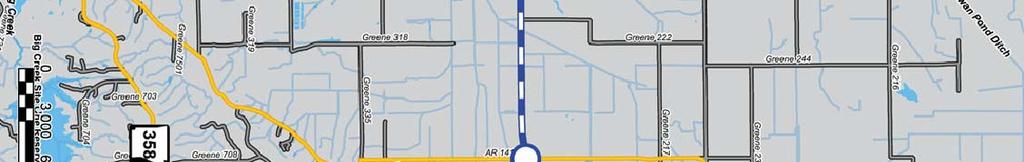

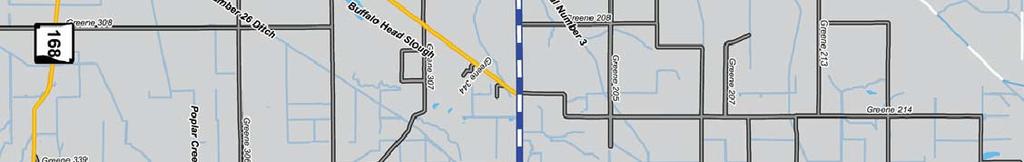
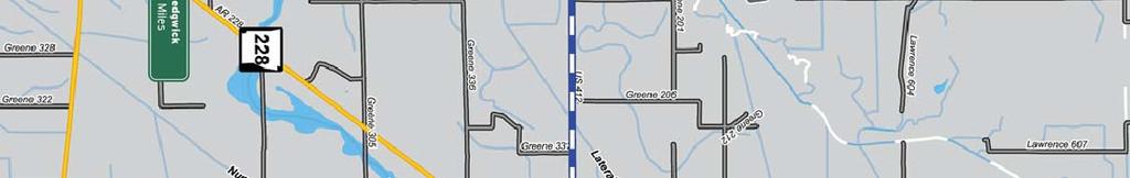

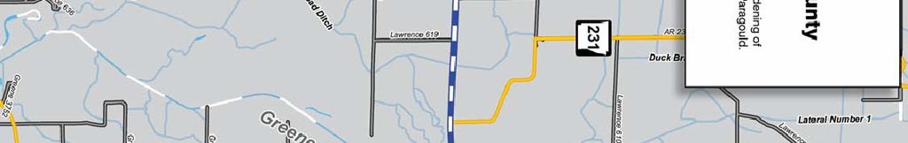
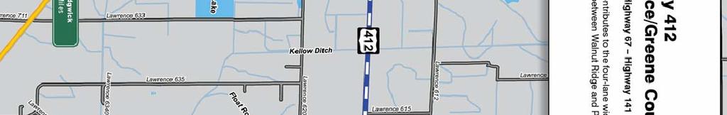

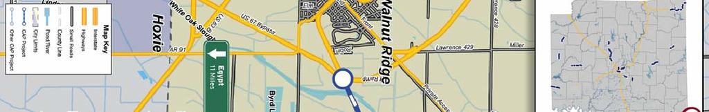
87