Application for a Dam Permit Ash Basin No. 1
|
|
|
- Anissa Long
- 5 years ago
- Views:
Transcription

1 Application for a Dam Permit Ash Basin No. 1 for the Sunbury Generating Station Shamokin Dam, Pennsylvania submitted to Commonwealth of Pennsylvania Department of Environmental Protection Bureau of Waterways Engineering and Wetlands Division of Dam Safety Harrisburg, Pennsylvania February 2014 ARCHITECTURE ENGINEERING COMMUNICATIONS TECHNOLOGY AVIATION CIVIL CONSTRUCTION SERVICES DATA SYSTEMS ENVIRONMENTAL FACILITIES ENGINEERING GEOSPATIAL NETWORKS PUBLIC SAFETY TRANSPORTATION
2 TABLE OF CONTENTS Page No. 1.0 Introduction... 3 Site Location Map DESIGN & CONSTRUCTION Site and Construction Materials Hydrologic and Hydraulic Information Watershed Information Size Classification Outlet Structure Calculations Breach Analysis Floodplain Management Analysis... 8 Flood Insurance Rate Map Risk Assessment Environmental Assessment Alternatives Analysis Mitigation Plan Proof of Title or Flowage of Easements Proof of Financial Responsibility Data on Site and Construction Materials Design Drawings Erosion and Sedimentation Control Plan Stormwater Management Plan Emergency Action Plan Operation and Maintenance Plan Instrument Monitoring Plan Engineer Certification APPENDICES Appendix A: Appendix B: Appendix C: Appendix D: Appendix E: Appendix F: Appendix G: Appendix H: Appendix I: Appendix J: Appendix K: Appendix L: Appendix M: Appendix N: Appendix O: Appendix P: Appendix Q: Appendix R: Appendix S: Permit Application General Information Form Act 14 Notification Correspondence Cultural Resources Notice PNDI Review and Correspondence Site Photographs Erosion & Sedimentation Control Plan Breach Analysis Environmental Assessment Form Proof of Financial Responsibility (Bonding) Instrument Performance Monitoring Program Material Chemical Data Operation and Maintenance Manual Emergency Action Plan Project Drawings Alternatives Analysis Closure / Post-Closure Plan Mitigation Plan Geotechnical Exploration and Stability Analysis Report K:\ \c\c\a\r\a\d\r\01-Permit Application Document 2 L.R. Kimball
3 Application for a Dam Permit Ash Basin No. 1 Sunbury Generating Station 1.0 INTRODUCTION Residual Ash Basin No. 1, hereafter referred to as the Basin is located at the Sunbury Generating Station in Shamokin Dam, Monroe Township, Snyder County, PA. This report contains the narrative description, drawings, calculations, Geotechnical Exploration and Stability Analysis Report, and permit applications for a Dam Safety Permit. The Basin was not previously permitted as a dam, but is permitted as a Residual Waste Disposal Facility by the Pennsylvania Department of Environmental Protection (PADEP), Bureau of Waste Management, North- Central Regional Office, as Facility ID No , owned by Sunbury Generation, LP, P.O. Box 517 Old Trail Road, Shamokin Dam, PA. The Basin is an unlined, diked impoundment, with a permit area encompassing approximately 62 acres, including the berm. The area within the berm available for waste disposal is slightly less than 56 acres. The facility began operation in 1949 and received bottom ash and fly ash from the generating station. Over the years, the ash basin has received coal combustion by-products from the power plant (coal rejects, fly ash and bottom ash), as well as water treatment plant sludge, stormwater runoff, various treated plant waste water streams, river silt from water intake tunnel cleanings, and captive clean construction demolition wastes. The impoundment is located along the western shore of the Susquehanna River. It is bounded to the east by the Susquehanna River, to the south by Rolling Green Run, to the west by industrial and residential land and Old Trail Road, and to the north by the Sunbury Electrical Substation and Power Generating Station. Remnants of a former canal that paralleled the Susquehanna River remain visible along the toe of the eastern ash basin berm. As noted above, the Basin is an existing structure for which a Dam Safety Permit is being sought, due to policy changes by the PADEP in dealing with Coal Combustion Waste Impoundments. The Basin area was originally a borrow site that provided soil for the construction of the Sunbury generation plant and related facilities. After the borrow site was initiated, the Basin was constructed by building a berm on the north, east (Susquehanna River side), and south sides. The elevation of the top of the berm originally varied from approximately 442 to 444 feet above mean sea level (AMSL), with the western side being at natural grade. The berm has been elevated to its current configuration (approximate minimum elevation 447 throughout) over the years to provide additional storage capacity for the basin. There have been no slope failures or stability problems reported since the berm was constructed, and the Basin has been in continuous use as a disposal facility throughout its life. K:\ \c\c\a\r\a\d\r\01-Permit Application Document 3 L.R. Kimball

4 Title: SUNBURY GENERATING STATION ASH BASIN NO. 1 SNYDER COUNTY SHAMOKIN DAM, PA Client: Scale FIGURE 1 - SITE LOCATION MAP SUNBURY GENERATION LP PO BOX 517, OLD TRAIL ROAD SHAMOKIN DAM, PA Date Project Number Drawn By Checked By Sheet Number
5 2.0 DESIGN & CONSTRUCTION 2.1 Site and Construction Materials Information concerning foundation materials, subsurface exploration, soils laboratory testing, and stability of the dam are provided in Appendix S. Information on the geology and soil properties were submitted to the PADEP Division of Solid Waste in 2008 as part of the Residual Waste Permit Renewal Package. 2.2 Hydrologic and Hydraulic Information Watershed Information Although the Basin permit boundary for the Residual Waste Permit has a total area of 62 acres, the disposal site drainage area is restricted to the top of the impoundment embankment and is slightly less than 56 acres. The impoundment discharges through an NPDES monitoring point to the Rolling Green Run Watershed. Rolling Green Run is classified as a Warm Water Fishery (WWF), by the Pennsylvania Fish and Boat Commission. Precipitation into the impoundment is directed to the south end of the Basin, through a settling area, and then into a riser structure connected to a 36 diameter steel outlet pipe which drains to Rolling Green Run. The pipe outlet has a weir and meter at the downstream end for measuring discharge at an NPDES permitted discharge location, approximately 900 upstream from the confluence of Rolling Green Run and the Susquehanna River Size Classification Aerial photography of the site was obtained on November 6, 2012, and topographic mapping of the existing conditions was compiled from that photography. Hydrographic mapping of the inundated areas of the impoundment, collected in May of 2012, was linked to the more recent topographic mapping to create an approximate top-of-ash contour plan representing what is considered existing conditions. At the time of the aerial photograph, the impounded water in the south end of the Basin was at elevation (As such, all contours within the Basin shown on the topographic mapping as being lower than that elevation were obtained from the hydrographic survey.) Drawings from the 2008 Residual Waste Permit Modification Application show the impoundment bottom at approximate elevation 425 on the south and west sides of the embankment and at 429 on the east and north sides of the embankment. The Residual Waste Permit drawings also show the original embankment height as The geotechnical investigation completed in the Fall of 2013 identified ash material as deep as elevation 420 (as shown in boring SB-9), but was typically closer to elevation 430 over most of the site. For volume computation purposes, the bottom was conservatively assumed to be as defined on the Residual Waste Permit drawings, with supplemental information from the boring logs. Based on the estimated bottom of the basin, there is approximately 1,200 acre-feet of disposed material within the impoundment. Approximately 55 acre-feet of the material is soil that is stockpiled for future closure. Due to the dry nature of much of the material in the Basin, a significant portion of the disposed material has been placed above the top of dam elevation (mounded in anticipation of final grading). The volume of water impounded to the normal pool elevation of 440 is approximately 16.9 acre-feet, based on the 2012 hydrographic mapping. The remaining capacity of the Basin (between normal pool elevation 440 and top of dam elevation 447) is 78.4 acre feet. As such, the remaining total impounding capacity to K:\ \c\c\a\r\a\d\r\01-Permit Application Document 5 L.R. Kimball
6 the top of the embankment is the sum of these, or 95.3 acre feet (excluding the 1,200 acre feet of coal combustion and soil material already in place). The impoundment at the southern end of the Basin is currently operated with approximately 7 feet of freeboard, measured from the normal pool level to the embankment low spot. The top elevation of the basin embankment is fairly consistent at elevation 447. The PADEP requires that the basin have a size classification based on the entire impounding capacity of the Basin, including the previously disposed material. Therefore, the basin is classified as a Class B Impoundment, with greater than 1,000 Acre Feet of storage, but less than 50,000 Acre Feet. Water levels from historic monitoring and the geotechnical investigation completed in 2013 show that the majority of the waste material is dry and stable. After closure, the Basin will have an effective impounding capacity of 0.0 acre-feet at the normal pool elevation of 435, and 68.9 acre-feet at the top of dam elevation of 447. At that time, the closed Basin s storage and height will be below the size classification to require a dam permit Outlet Structure Calculations The Impoundment is drained by a decant structure located at the southeast end of the Basin. The decant structure consists of a 6.25 x 7.5 rectangular concrete riser. The side of the riser structure facing the Basin is open and slotted to accommodate wooden stop logs for controlling the Basin pool elevation. The stop logs are 5.5 in length and provide weir flow control for the structure. A 36 diameter concrete pipe exits the structure at an invert elevation of The outlet pipe is approximately 80 in length with a slope of roughly 2% and outlet invert elevation of The structure configuration is shown on Exhibit FG-5 from the 2008 Residual Waste Permit Modification Application, included in Appendix O. A 36 by 36 square box is currently attached to the front of the outlet structure by a 24 Smooth Lined Corrugated Polyethylene Pipe (SLCPP). This box is used as an inlet for a nearby sump pump and for a 24 diversion pipe from the bottom ash sluice trench to reduce the concentration of suspended solids at the NPDES discharge location, prior to discharge. For the hydraulic analysis, the outlet structure was modeled as a weir at elevation 440. The current configuration with the 24 SLCPP pipe and the outlet box will not significantly reduce the structure s hydraulic capacity, and is only temporary. The stop logs above elevation 440 will be removed from the structure to ensure sufficient flow. Discharge calculations for the riser pipe and associated discharge pipe are included in Appendix H Breach Analysis Based on the size and downstream structures, the Basin is considered to be Hazard Category 2, and Size Classification B. PA Chapter 105 Regulations; Section specifies a Hazard Potential Classification of 2 for dams which have no more than a small number of habitable structures. There are several small cottages along the Susquehanna River to the south of the impoundment which could potentially be affected by a sudden failure of the dam during a Probable Maximum Precipitation (PMP) storm. These structures are also within the Susquehanna River s 100 year floodplain. Section of Chapter 105 specifies that the Design Flood Criteria of a B-2 dam should be between ½ of the Probable Maximum Flood (PMF) and PMF. At the request of the PADEP reviewer, the basin was evaluated for a PMF. The basin was also evaluated for overtopping for a 100 year frequency SCS-Type II storm, based on the premise that its post closure impounding capacity and height would be less than PADEP dam permit criteria. K:\ \c\c\a\r\a\d\r\01-Permit Application Document 6 L.R. Kimball
7 The 100 year frequency SCS-Type II and PMP storms, were evaluated using the United States Army Corps of Engineer s Hydrologic Engineering Center Hydrologic Modeling System (HEC-HMS) Software. As noted above, the discharge structure was modeled as a weir at elevation 440. A 24 hour / 100 year frequency storm for the basin area results in 6.96 of precipitation. The HEC-HMS model shows that a 100-year storm will result in a peak inflow of cubic feet per second (CFS), peak outflow of 20.4 CFS, and a peak water elevation of ft. Therefore, a 100 year storm can be safely passed by the existing outlet structure and available storage capacity, if the stop logs above elevation 440 are removed. The PMP storm was modeled using a 34 rainfall as provided from HMR-51 for a 24-hour, 10 square mile drainage area in the Shamokin Dam area. The time distribution of the precipitation was determined in accordance with the USACE Bulletin 52-8, Plate 11, which bases the 3, 2, and 1 hour precipitation intensities on percentages of the 6 hour precipitation from HMR-51. The basin was modeled two different ways. The first model used the current stage storage curve and starting water surface elevation of 440. This model did not model a breach of the embankment and resulted in a peak inflow of 592 CFS, peak outflow of CFS, and a peak water elevation of ft. The model resulted in overtopping of the dam by 0.3 feet and a peak overtopping flow of cfs. In the second model, the basin stage storage curve was manipulated to double the capacity and therefore double the outflow volume. This was done at the request of the PADEP to estimate the effects of having a volume of slurry material, equal to the volume of water discharged during the breach event. The starting water surface elevation was adjusted to elevation 443 to produce a peak water elevation similar to the results for the first model. This model included a dam break, simulating a breach of the impoundment over a half hour time interval, and assuming 1:1 side slopes, a breach bottom elevation of 430, and bottom width of 51, which is 3 times the breach depth. The breach was initiated when the reservoir level reached elevation The breach model resulted in a peak inflow of 592 CFS, peak outflow of CFS, and a peak water elevation of ft. The drainage area for Rolling Green Run was also modeled for the PMP storm and resulted in a peak discharge of CFS. The peak discharge for Rolling Green Run at the Ash Basin breach location occurred at approximately hours into the storm. This peak flow was significantly later in the storm than the peak flow from the Ash Basin breach, which occurred at 13.5 hours into the storm. As a result, the peak flow for Rolling Green Run downstream of the breach is less than the sum of the Ash Basin breach and the Rolling Green Run drainage area peak flows. The Hydrograph for the breach model was entered into Hydrologic Engineering Center River Analysis System (HEC-RAS) Software. Seven cross sections along Rolling Green Run were constructed using Lidar Data available on the Pennsylvania Spatial Data Access (PASDA) website. The HEC-RAS model used unsteady flow from the Rolling Green Run drainage area and from the Ash Basin breach. The Rolling Green Run valley is somewhat unusual in that significant discharges would result in flows to the northeast (along Rolling Green Run into the Susquehanna River) and to the south (along the valley west of River Road). In the event of a large discharge, or a dam breach, the flow would be divided, creating a complex hydraulic condition that is very difficult to model. To simplify the model, and to create conservatively high flood levels for the inundation map, all flow from Rolling Green Run and the breach was assumed to flow through the Rolling Green Run stream channel to the Susquehanna River, by creating an artificial barrier on the south side. This approach allowed for K:\ \c\c\a\r\a\d\r\01-Permit Application Document 7 L.R. Kimball
8 conservative estimation of the possible flood wave elevation in relation to the cottages directly south of the basin. As noted above, this model does not account for flow to the south between River Road and old trail road, since that would have resulted in lower (i.e., less conservative) flood wave elevations. However, flows to the south, parallel to River Road, would result in overtopping of the roadway used for access to the cottages. As such, the Emergency Action Plan will identify traffic access points on River Road and 10 th Street, even though they are not shown within the inundation area, as currently modeled. The conservative model shows that several of the cottages would be impacted by the flood wave, which has a peak elevation of at the cross section nearest the cottages. Lidar contours indicate ground elevations ranging from 432 to 436 in the vicinity of the cottages. Although the emergency spillway does not pass the PMP storm, increasing its capacity does not appear to be warranted, since the computed model is shown to be extremely conservative, and because the basin will have reduced impounding capacity after closure of the facility. It is the owner s intent that the post closure impounding capacity and height will be less than PADEP dam permit criteria. The HEC-HMS and HEC-RAS models are included in Appendix H. 2.3 Floodplain Management Analysis The 100 year floodplain elevations along the Susquehanna River in the vicinity of the Basin range from elevation 441 to 442, as shown on Figure 2 Flood Insurance Rate Map, based on the current FEMA Flood Insurance Study. (See the following page). Since the Basin top of dam elevation is 447, the entire Basin is outside of the Susquehanna River floodplain for the 100-year storm event. However, portions of the basin are listed on the Flood Insurance Rate Map as Zone X, which includes: Areas of 0.2% annual chance of flood; areas of 1% annual chance flood with average depths of less than 1 foot or with drainage areas less than 1 square mile; and areas protected by levees from 1% annual chance or flood. Those portions of the Basin which are shown within Zone X are below the 100 year flood elevation, and could be inundated by water backing up into the Basin from the outlet pipe and structure. In order to prevent water entering the Basin, a one way or duckbill valve should be installed on the downstream end of the outlet pipe. K:\ \c\c\a\r\a\d\r\01-Permit Application Document 8 L.R. Kimball
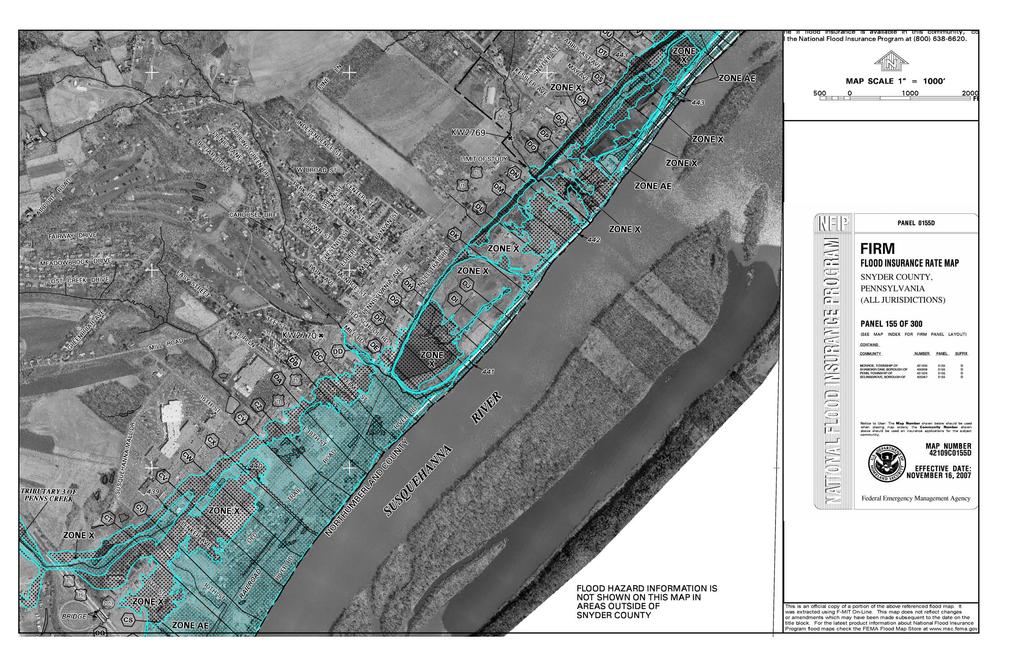
9
10 2.4 Risk Assessment The stormwater and floodplain management analysis did not indicate an increased risk to life, property, or the environment. This permit application does not affect the current use of the land or the planned closure, but provides information and plans already approved as part of the existing Residual Waste Disposal permit for the basin. 2.5 Environmental Assessment An Environmental Assessment was performed as part of the Residual Waste Permit Renewal Package submitted to the PADEP Division of Solid Waste in That assessment is included in the submission as Appendix I. The assessment notes wetlands within the permitted disposal area. However, these wetland areas are non-jurisdictional areas, as they are located within the ash disposal are and are exempt based on the existing residual waste permit. No wetlands outside of the permitted disposal area will be affected during closure of the basin. 2.6 Alternatives Analysis An Alternatives Analysis, consistent with the requirements listed in the Instructions for Completing Dam a Permit, is included in Appendix P. 2.7 Mitigation Plan A Mitigation Plan, consistent with the requirements listed in the Instructions for Completing Dam a Permit, is included in Appendix R. 2.8 Proof of Title or Flowage of Easements Residual Ash Basin No. 1 is a captive disposal facility, completely contained within the property limits owned and operated by Sunbury Generation LP. The site is permitted as a Residual Waste Disposal Facility by the PADEP, Bureau of Waste Management, North-Central Regional Office, as Facility ID No The property boundary is shown on Figure FG-1, in Appendix O. 2.9 Proof of Financial Responsibility The site is permitted as a Residual Waste Disposal Facility by the PADEP, Bureau of Waste Management, North-Central Regional Office, as Facility ID No As part of the Residual Waste Disposal Permit, the owner is required to maintain a bond for closure of the disposal site, which includes construction of an 18 inch thick soil/ash mix cap, installation of E&S structures, revegetation, long term sampling of the on-site monitoring wells, and long term maintenance of the site. As part of the closure the impounding capacity of the site will be reduced to that required for stormwater management of the facility. Therefore the current bonding for closure will cover the activities required for continued operation and maintenance of the facility and stabilization of the site. The updated bonding calculations and narrative, which were approved by the Bureau of Waste Management are included in Appendix J Data on Site and Construction Materials L.R. Kimball conducted a geotechnical investigation of the Residual Ash Basin No. 1 between September 26 and October 10, A Geotechnical Exploration and Stability Analysis Report documenting the site investigation, and including a boring location map, exploratory boring logs, piezometer installation sketches, K:\ \c\c\a\r\a\d\r\01-Permit Application Document 10 L.R. Kimball
11 long term water level data readings, laboratory test results, geologic cross sections, and slope stability analyses, is included in Appendix S. Data on the geotechnical characteristics of the existing ash material, as well as the soil material used for construction of the perimeter berm, is included in the Geotechnical Report. Since the Basin has been permitted as a captive Residual Waste Disposal Impoundment by the PADEP, Bureau of Waste Management, North-Central Regional Office, data on the chemical content and other (nongeotechnical) characteristics have been submitted as part of the Residual Waste Permit Application. A discussion of the chemical content of the disposed materials is included in Appendix L. The final cover that will be used for the Closure Plan will consist of an 18 inch layer of a soil/fly ash mixture, using materials that are present at the site. The soil material that is proposed for use in the final cover was imported from off-site construction projects, and is currently stockpiled on-site, awaiting final closure. A discussion of this soil material is included in the Erosion and Sedimentation Control Plan, included in Appendix G Design Drawings Residual Ash Basin No. 1 is an existing structure, originally constructed in 1949 by the Pennsylvania Power and Light Company (PP&L) for disposal of ash material from the Sunbury Power Plant. It has been in continuous use as an ash disposal facility since original construction. With that in mind, the drawings included Appendix O, are primarily intended to present existing site conditions, and proposed Closure Plans. Additional Drawings are included in the Geotechnical Exploration and Stability Analysis Report, in Appendix S, to document the site investigation and slope stability analyses Erosion and Sedimentation Control Plan As part of the permit application for continued operation as a captive Residual Waste Disposal Impoundment, an Erosion and Sedimentation Control Plan was prepared using the PADEP, Bureau of Waste Management Form I. A copy of that form is included in Appendix G Stormwater Management Plan Since the Basin has been permitted as a captive Residual Waste Disposal Impoundment by the PADEP, Bureau of Waste Management, North-Central Regional Office, and has been operating as a permitted residual waste disposal facility since 1949, the stormwater management issues discussed in this Dam Safety Permit Application submission are focused on two different scenarios: Existing conditions under the design storm, with and without a dam breach (see Appendix H) Stormwater management during closure and post-closure. (see Appendix G) Both of these issues are discussed in more detail in Section Emergency Action Plan As required in the Instructions for Completing a Dam Permit, an Emergency Action Plan (EAP) has been prepared, and is included in Appendix N. The EAP was developed in accordance with the most recent EAP Guidelines from the DEP Division of Dam Safety Operation and Maintenance Plan K:\ \c\c\a\r\a\d\r\01-Permit Application Document 11 L.R. Kimball
12