Flue-Gas Water as a Resource for Carbon-Capturing Power- Plants
|
|
|
- Justin Stephens
- 5 years ago
- Views:
Transcription
1 Flue-Gas Water as a Resource for Carbon-Capturing Power- Plants Danylo Oryshchyn, Thomas Ochs, Casey Carney, Stephen Gerdemann, Cathy Summers, Paul King
2 Basic Process Outline Combust fuel in directly-supplied (not aircarried) oxygen. Undiluted products of combustion Capture combustion products to capture the CO 2 component Cooling and compression (part of the capture process) produce condensed flue- gas water
3 Combustion Products air-firing i oxy-firing i H 2 O 9.2% O 2 35% 3.5% SO 2 0.2% O 2 3.5% SO 2 0.9% N 2 2.1% CO % H % 2 air-fired flue gas N % oxy-fired exhaust CO %
4 Water/energy: The Oxy-Combustion with Integrated t t d Pollutant t t Removal l (IPR) effort Water previously released to the atmosphere now presents a resource Energy (heat recovery) Heat-exchange medium Combustion-optimization optimization (completion of combustion)
5 Air-Firing Combustion products Boiler Fuel
6 Air-Firing
7 Oxy-Firing/IPR To next stage Compression, intercooling, postcooling Reagent addition Water treatment Contaminants Boiler Cyclone Combustion products Direct contact heat exchanger Flue-gas water Pure water Indirect heat exchange Fuel IPR Bleed Stream Pump Oxygen Plant Filter Energy released in combustion is recovered through integration of feedwater heating and flue-gas cooling. Water is a by-product of this energy recovery.
8 Oxy-Firing/IPR
9 Integrated Pollutant Removal (IPR) System Base Press. Temp. ph TWR 45 H2 190 H3 H4 H STG1 STG2 STG3 STG4 FGR tap V4 V8 V11 CAPTURE H1
10 Water Opportunities Pollutants that now interact with atmospheric water are capturable from point-source liquid water Correctly applying recovered energy and water within the thermal cycle can maximize fuel efficiency (more fully using the energy entering with the fuel) Flue-gas water massflow offsets massflow of water required for thermal power production
11 Questions for research Highly-efficient purification processes for released water Optimal full-use use applications for recovered water Economic opportunities for material recovered during water purification
12 What we are finding in IPR May be able to use less water in Flue-Gas Desulphurization (FGD) Sulfur capture effective at pressure Species reporting at intercooler locations
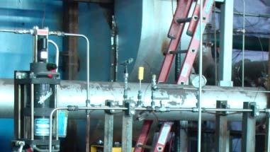


13 Installation in the Field Cooperator Boiler Test Facility (Hammond, IN) TWR H2 H3 H4 H5 CAPTURE
14 Recovering Water Process Base Condensates From H1 Dissolved Material Ba, 0.09 Ba, 0.05 Ca, ph TWR 45 H2Cl, H3 H4 H5 Cr, 3.0 Cr, Cr, Cu, Cu, STG1 Fe, 2.9 STG2 Fe, STG3 STG4 Hg, 3.2E-04 Hg, Mg, 3.9 Mo, Mo, Na, 10,853 V4 Ni, 6.6 Ni, 26 V8 V11 NO2, 1,437 NO3, 4.0 NO3, 994 NO3, 118,073 H1 SO4, SO4, 3,025 SO4, 13,375 64,377 Zn, 4.1 solids, ppm
15 Recovering Water Process Base Condensates From V4 Dissolved Material Ba, 0.05 Ca, ph TWR 45 H2Cl, H3 H4 H5 Cr, 3.0 Cr, 13 Cu, 0.9 STG1 STG2 STG3 STG4 Hg, 3.2E-04 H1 Fe, 2.9 Mg, 3.9 Mo, 2.0 NO3, 4.0 Fe, 163 Na, 10,853 V4 V8 V11 Ni, 6.6 NO2, 1,437 NO3, 994 SO4, SO4, 3,025 13,375 solids, ppm
16 Recovering Water Process Base Condensates From V8 Dissolved Material Ca, 81 ph TWR 45 H H3 H4 H5 Cr, 3.0 Cu, 0.9 STG1 STG2 STG3 STG4 Fe, 2.9 H1 Mg, 3.9 Mo, 2.0 NO3, 4.0 Na, 10,853 V4 V8 V11 NO2, 1,437 SO4, 13,375 solids, ppm
17 One Possible Approach Combustion products, entraining fine particulate (not caught in cyclone) sent counter-current current to flue-gas-water spray to remove the bulk of the particles left. Scrubber may employ bases to react with Scrubber may employ bases to react with the SOx if needed.
18 One Possible Approach The scrubber traps gas constituents that are water soluble as well as chemicals that leach out of the particles trapped in the scrubber. Particles trapped by the scrubber are filtered out. Scrubber water Treat for reuse as spray
19 One Possible Approach Treatment for water-offset applications ph-swing precipitation and filtration Demineralization (using ion exchange resins) Testing for usage Reuse in the cooling loop (IPR, or Plant at large) Release
20 Summary Recovering energy leads to recovering water Water removes pollutants from CO 2 Chemically adjusting water for thermal- cycle application Preventing release of those pollutants with returned water
21 Thank you for your attention.
22 Exhaust Composition Conventional after economizer Oxyfuel exhaust after splitter After 1 st compression After 2 nd compression After 3rd compression Gas Flow (kg/hr) 1,716, , , , ,630 Vol flow (m 3 /hr) 1,932, ,092 72,623 15, Inlet Pressure () ,500 Inlet Temperature ( F) Density (kg/m 3 ) H 2 O (fraction) Ar (fraction) CO 2 (fraction) N 2 (fraction) O 2 (fraction) SO 2 (fraction)