NEARLY ZERO ENERGY BUILDING RETROFIT SAP Dr Luisa Brotas
|
|
|
- Sybil Bell
- 5 years ago
- Views:
Transcription
1 NEARLY ZERO ENERGY BUILDING RETROFIT SAP 2012 Dr Luisa Brotas 4-8 July 2016

2 SAP EDITION 2012 SAP is the Government sstandard Assessment Procedure for Energy Rating of Dwellings. Assesses the energy performance of dwellings.
, 3. Environmental Impact rating based on CO 2 emissions (the EI rating) 4. Dwelling CO 2 Emission Rate (DER).")
3 Indicators The indicators of energy performanceare: 1. Fabric Energy Efficiency (FEE), energy consumption per unit floor area, (KWh/m 2 ) 2. Energy cost rating (the SAP rating), 3. Environmental Impact rating based on CO 2 emissions (the EI rating) 4. Dwelling CO 2 Emission Rate (DER). Source
4 Ratings SAP rating: E cost/m 2 (1-100) Environmental Impact rating (EI): CO 2 ann. /m 2 (1-100) Dwelling CO 2 emission rate (DER): CO 2 ann. /m 2 kg/m²/year

5 SAP rating band The SAP rating scale has been set so that SAP 100 is achieved at zero-ecf. It can rise above 100 if the dwelling is a net exporter of energy. The SAP rating is essentially independent of floor area. Rating Band 92 or more A 81 to 91 B 69 to 80 C 55 to 68 D 39 to 54 E 21 to 38 F 1 to 20 G

6 Carbon Dioxide Emissions and Primary Energy The EI rating scale has been set so that EI 100 is achieved at zero net emissions. It can rise above 100 if the dwelling is a net exporter of energy. The EI rating is essentially independent of floor area. Primary energy is calculated in the same way as CO 2 emission using the primary energy factors in Table 12 in place of the CO 2 emission factors. Rating Band 92 or more A 81 to 91 B 69 to 80 C 55 to 68 D 39 to 54 E 21 to 38 F 1 to 20 G


7 Ratings SAP rating and annual CO 2 emissions associatedwith regulated energy consumption space heating, water heating, ventilation and lighting, lesscost savings from energy generation technologies. It is adjusted for floor area so that it is essentially independent of dwelling size for a given builtform. DER is used for the purposes of compliance with building regulations as Part L1. It is equal to the annual CO 2 emissions per unit floor area (regulated energy consumption CO2saved). kg/m²/year. Energy Performance Certificate For Training Purposes Only Sample EPC TheDomesticEnergyAssessor.com... xxxxthis home's performance is rated in terms of the energy use per square metre of floor area, energy efficiency based on fuel costs and environmental impact based on carbon dioxide (CO2) emissions. Energy Efficiency Rating Very energy efficient - lower running costs (92-100) (81-91) (69-80) (55-68) (39-54) (21-38) (1-20) A B Not energy efficient - higher running costs England & Wales C D E F G Current 59 EU Directive 2002/91/EC Potential The energy efficiency rating is a measure of the overall efficiency of a home. The higher the rating the more energy efficient the home is and the lower the fuel bills will be. Dwelling type: Date of assessment: Date of certificate: Reference number: Total floor area: Environmental Impact Rating Estimated energy use, carbon dioxide (CO2) emissions and fuel costs of this home 71 Very environmentally friendly - lower C02 emissions Not environmentally friendly - higher C02 emissions England & Wales Mid-terrace house 09 June August m2 The environmental impact rating is a measure of a home's impact on the environment in terms of carbon dioxide (CO2) emissions. The higher the rating the less impact it has on the environment. Current Potential Energy use 302 kwh/m2 per year 212 kwh/m2 per year Carbon dioxide emissions 5.5 tonnes per year 3.9 tonnes per year Lighting 85 per year 44 per year Heating 516 per year 414 per year Hot water 162 per year 93 per year Based on standardised assumptions about occupancy, heating patterns and geographical location, the above table provides an indication of how much it will cost to provide lighting, heating and hot water to this home. The fuel costs only take into account the cost of fuel and not any associated service, maintenance or safety inspection. This certificate has been provided for comparative purposes only and enables one home to be compared with another. Always check the date the certificate was issued, because fuel prices can increase over time and energy saving recommendations will evolve. To see how this home can achieve its potential rating please see the recommended measures. (92-100) (81-91) (69-80) (55-68) (39-54) (21-38) (1-20) Current EU Directive 2002/91/EC Potential Remember to look for the energy saving recommended logo when buying energy efficient product. It's a quick and easy way to identify the most energy efficient products on the market. For advice on how to take action and to find out about offers available to help make your home more energy efficient call or visit A B C D E F G For Training Purposes Only Page 1 of 8
 solar gains through openings of")
8 Energy balance The calculation is based on the energy balance taking into account a range of factorsthat contribute to energy efficiency: materials used for construction of the dwelling thermal insulation of the building fabric air leakage ventilation characteristics of the dwelling, and ventilation equipment efficiency and control of the heating system(s) solar gains through openings of the dwelling the fuel used to provide space and water heating, ventilation and lighting energy for space cooling, if applicable renewable energy technologies Calculation Factors Source : Aritz Moriones
9 Limitations The calculation is independent of factors related to the individual characteristics of the household occupying the dwelling when the rating is calculated, for example; household size and composition; ownership and efficiency of particular domestic electrical appliances; individual heating patterns and temperatures. Therefore in SAP calculations dwellings have a standard occupancy and usage pattern, which adopt typical values of quantities that in practice vary substantially between dwellings of similar size and type. The occupancy assumed for SAP calculations is not suitable for design purposes, for example of hot water systems.
10 Scope of the procedure The procedure is applicable to self-contained dwellings (of any size and any age). For flats, it applies to the individual flat and does not include common areas such as access corridors. Wherepart of an accommodation unit is used for commercial purposes (e.g. as an office or shop), this part should be included as part of the dwelling if the commercial part could revert to domestic use on a change of occupancy. That would be applicable where: - there is direct access between the commercial part and the remainder of the accommodation, and - all is contained within the same thermal envelope, and -the living accommodation occupies a substantial proportion of the whole accommodation unit. Wherea self-contained dwelling is part of a substantially larger building, wherethe remainder of the building would not be expected to revert to domestic use, the dwelling is assessed by SAP and the remainder by procedures for non-domestic buildings.

11 Type of property DETACHED SEMI-DETACHED MID-TERRACE END-TERRACE ENCLOSED MID-TERRACE ENCLOSED END-TERRACE A house or bungalow has a complete heat loss ground floor and a completely exposed roof. A dwelling without a heat loss floor cannot be a house and must be treated as a flat or maisonette. A flat or maisonette does not have both a heat loss ground floor and a heat loss roof. SAP makes no distinction between a flat and a maisonette. Source : Aritz Moriones
12 Terrain : Wind Energy The terrain type will affect the energy generated by any Micro Wind Turbines that are part of the dwelling. A Rural terrain will improve the performance of a wind turbine. Dense urban (city centres with mostly closely spaced buildings of four storeys or higher) Low rise urban / suburban (town or village situations with other buildings well spaced)
13 Sheltered sides A side of a building is sheltered if there are adjacent buildings or tree-height hedges which effectively obstruct the wind on that side of the building. A side should be considered sheltered ifall the following apply: -the obstacle providing the shelter is at least as high as the ceiling of the uppermost storey of the dwelling; -the distance between the obstacle and the dwelling is less than five times the height of the obstacle; - the width of the obstacle (or the combined width of several obstacles) is such that it subtends an angle of at least 60 within the central 90 when viewed from the middle of the wall of the dwelling thatfaces theobstacle.
14 Living area Living Area The living area is the room marked on a plan as the lounge or living room, or the largest public room (irrespective of usage by particular occupants), together with any rooms not separated from the lounge or living room by doors, and including any cupboards directly accessed from the lounge or living room. Living area does not, however, extend over more than one storey, even when stairs enter the living area directly. The living area fraction is the floor area of the living area divided by the total floor area. KITCHEN RECEPTION ROOM 1 UTILITY CLKS RECEPTION ROOM 2 HALL STUDY GROUND FLOOR
15 Dwelling Dimensions KITCHEN RECEPTION ROOM 1 Any internal elements (internal partition walls or intermediate floors within the dwelling) are disregarded for the purposes of establishing areas. UTILITY CLKS RECEPTION ROOM 2 HALL STUDY GROUND FLOOR
16 Dwelling Dimensions Storey height is the total height between the ceiling surface of a given storey and theceiling surface of the storey below. For a single storey dwelling, or the lowest floor of a dwelling with more than one storey, the measurement should be from floor surface to ceiling surface. Where the room height varies, such as in a room-in-roof, the storey height should be an average based on the volume of the space and the internal floor area (plus the thickness of the floor if it is the upper storey of a house). Floor area should be measured as the actual floor area (G.I.A), i.e. if the height of a room extends to two storeys or more only the actual accessible floor area should be used for the calculations. However, as an exception to this rule in the case of stairs, the floor area should be measured as if there were no stairs but a floor in their place at each level. In general, rooms and other spaces, such as built-in cupboards, should be included in the calculation of the floor area where these are directly accessible from the occupied area of the dwelling. However unheated spaces clearly divided from the dwelling should not be included.
17 PART L1B
18 Heat Transmission The areas of building elements are based on the internal dimensions of surfaces bounding the dwelling. U-value for a window should be that for the whole window opening, including the window frame. For existing dwellings see Appendix S for U-values for the envelope. U-values of opaque elements Window U-values U-values of elements adjacent to an unheated space Thermal bridging Dwellings that are part of larger premises Curtain walling Party walls
19 Ventilation The ventilation air change rate is the rate at which outside air enters/leaves a building. SAP requires a reasonable estimate of the air change rate in order to calculate the overall heating requirement. The actual ventilation rate depends on a large number of factors, many of which may not be known precisely (e.g. permeability of materials and inadvertent gaps and openings in the structure) and in most cases cannot be assessed from a site survey or from plans. The infiltration rate can be assessed either from: A pressurisation test or Utilising the SAP algorithm as defined by (9) to (16) of the worksheet.
20 Ventilation Chimneys and flues Ventilation rates for chimneys and flues should be counted only when they are unrestricted and suitable for use. For the purposes of the SAP a chimney is defined as a vertical duct for combustion gases of diameter 200 mm or more (or a rectangular duct of equivalent size). Vertical ducts with diameter less than 200 mm should be counted as flues.
21 Fans and passive vents Ventilation Intermittent-running extract fans which exhaust air (typically from the kitchen and bathroom), including cooker hoods and other independent extractor fans, should be included in the 'number of fans category. Passive stack ventilators (passive vents) are an alternative to extract fans. Such systems comprise extract grilles connected to ridge terminals by ducts. Such systems should be supplied with air bricks or trickle vents for air ingress. It is the number of extract grilles that should be used in the calculation. Trickle vents or air bricks alone do not count as passive vents and should not be included in the calculation. Please note that when you select a primary or secondary heating system with an open flue or chimney this information Will be Automatically Updated. Additionally, If you specify mechanical ventilation with Heat recovery (MVHR) the number of intermittent fans will automatically be set to 0.
. The pressurisation test should be carried out in accordance with BS EN 13829.")
22 Pressurisation test Ventilation A pressurisation test of a dwelling is carried out by installing a fan in the doorway of the principal entrance to the dwelling, sealing all flues and chimneys, and determining the air flow rate required to maintain an excess pressure of 50 pascals (Pa). The pressurisation test should be carried out in accordance with BS EN The air permeability measured in this way, q50, expressed in cubic metres per hour per square metre of envelopearea. The result of a pressure test, where available, is used instead of the default calculations of infiltration. Source : Aritz Moriones
23 Mechanical Ventilation Mechanical ventilation systems use continually running fans. They can be: input-only, extract-only or balanced (input and extract). Positive input ventilation (PIV) Mechanical extract ventilation (MEV) Balanced whole house mechanical ventilation The SAP calculation is based on 0.5 air changes per hour through the mechanical system, plus infiltration. In-use factors are applied in all cases to the Specific Fan Power (SFP) and, for Mechanical Ventilation with Heat Recovery (MVHR) systems, heat exchanger efficiency to allow for differences in practical installations compared to the laboratory test conditions that are defined for the SAP test procedure.
24 Thermal Bridges A thermal bridge, also called a cold bridge, is a fundamental of heat transfer where a penetration of the insulation layer by a highly conductive or non-insulating material takes place in the separation between the interior (or conditioned space) and exterior environments of a building assembly (also known as the building enclosure, building envelope or thermal envelope) A Thermal Bridge is a thermally conductive material which penetrates or bypasses an insulation system; such as a metal fastener, concrete beam, slab or column Typical effects of thermal bridges are: 1. Decreased interior surface temperatures; in the worst cases this can result condensation problems, particularly at corners. 2. Significantly increased heat losses. 3. Cold areas in buildings

25 Thermal Bridges
26 Thermal Bridges SAP allows you to enter the thermal bridging details of the dwelling. There are currently three options. 1. Enter the details of each junction if known. 2. Enter a global user defined value ( reference required) 3. Assume a value of 0.15 if neither of the above is known (This option will penalise your results)
27 There are three different options: Thermal Bridges 1. Accredited Construction Details Accredited Construction Details (ACDs) have been developed to assist the construction industry achieve the performance standards required to demonstrate compliance with the energy efficiency requirements (Part L) of the Building Regulations. The details focus on the issues of insulation continuity (minimising cold bridging) and airtightness. They are not intended to provide any detailed guidance on other performanceaspects. 2.Calculated Details (Penalty) Y-values have been calculated by a person with suitable expertise and experience in accordance with BRE IP 1/06. Y values are increased by 0.02 or 25% (whichever is the larger). 3. Default Values (++Penalty)
28 Linear Thermal Transmittance (Y -values) linear thermal transmittance, Ψ
29 Linear Thermal Transmittance (Y -values) Y-values are used for thermal bridging. There are three possibilities. a) The use of a global factor, which is multiplied by the total exposed surface area, as described in Appendix K. b) On the basis of the length of each junction and the default Y-values in Table K1. c) On the basis of the length of each junction and user-supplied Y-values. It is not necessary to supply Y-value for each junction type values from Table K1 can be mixed with user-supplied values.
30 Thermal Mass The Thermal Mass Parameter (TMP) is required for heating and cooling calculations. It is defined as the sum of (area times heat capacity) over all construction elements divided by total floor area. It can be obtained from the actual construction elements of walls, floors and roofs (including party and internal walls, floors and ceilings). For further details see Table 1e. Thermal mass is a concept in building design which describes how the mass of the building provides "inertia"against temperature fluctuations.
31 Thermal Mass - TMP Heat capacity per unit area, k in kj/m²k, for a construction element can becalculated from: k = 10-6 Σ(d j r j c j ) where: the summation is over all layers in the element, starting at the inside surface and stopping at whichever of theseconditions occurs first (which maymean part way through a layer): - halfway throughtheelement; - an insulation layer (thermal conductivity <= 0.08 W/m K); -total thickness of 100 mm. d j is the thickness of layer (mm) r j is density of layer (kg/m³) c j is specific heat capacity of layer (J/kg K) The elements to be included are walls, floors and roofs (windows and doors have negligible capacity), including all internal and party walls and floors. In the case of internal walls and floors, thecapacity is needed for each sideof the element.

32 Thermal mass Table 1e: Heat capacities for some common constructions
33 TMP Table 1f: Thermal Mass Parameter The k values are used to calculate the TMP variable (Thermal Mass Parameter), worksheet (35), which is used to characterise the thermal mass of the building. It is: where the summation is over all walls, floors and roofs bounding the dwelling (including party walls and floors/ceilings) togetherwith bothsides ofall internal walls and floors/ceilings. Indicative values of TMP are:
34 DHW Combi boiler A combination boiler with an internal hot water store may be either: primary a primary water store contains mainly water which is common with the space heating circuit. secondary a secondary water store contains mainly water which is directly usable as domestic hot water. Primary storage combi boiler Secondary storage combi boiler

.")
35 Solar Domestic Hot Water Solar DWH The performance of a solar collector is represented by its zero-loss efficiency (proportion of incident solar radiation absorbed in the absence of thermal loss) and its heat loss coefficient (heat loss from collector to the environment per unit area and unit temperature difference). Evacuated tube Glazed flat plate

36 Solar Domestic Hot Water V s (indicated by the dashed line) is the dedicated solar storage volume. See text below concerning the effective solar volume. Vd is the daily hot water demand. Solar DWH Rule of thumb Collector surface area: m 2 /pp Storage cylinder size: l/m 2 (collector surface area)

37 Overshading Front of dwelling and overshading information is used in the calculation of summer overheating. If these are not known, unknown can be selected however bear in mind that for the overheating calculation, the worst case orientation is assumed.
38 Windows Window U-values and g-values (total solar energy transmittance) can be from a certified window energy rating or manufacturers declaration. Both values are needed (for the calculation of respectively heat loss and solar gain). Values of light transmittance (gl ) are given in Table 6b for calculation of lighting energy requirements as set out in Appendix L.
39 Lighting Electricity for lighting The calculation allows for low-energy lighting provided by fixed outlets (both dedicated fittings and compact fluorescent lamps) on the basis of the proportion of the fixed outlets that have low-energy fittings. Low energy light percentage and the Low energy lighting outlets are used to calculate the artificial lighting energy consumption. In UK houses, the average annual energy consumption for lighting if no low-energy lighting is used is: EB = x (TFA x N) (L1) where TFA is the total floor area in m 2 and N is the assumed number of occupants (see Table 1b). The SAP calculation takes account of fixed lighting outlets with low-energy lamps, by including a correction factor C1 : C1 = x L LE /L Daylighting C2 = 52.2 GL GL if GL C2 = 0.96 if GL > 0.095
40 Lighting Daylighting Analysis of typical house types gives the following approximate correction factor, C2, for lighting energy use depending on the ratio of glass area to floor area, glass transmittance and light access factor. The initial value of the annual energy used for lighting in the house, EL, is then EL = EB x C1 x C2 kwh/year
41 Heating System The main heating system is that which heats the largest proportion of dwelling. It is a heating system which is not usually based on individual room heaters (although it can be), and often provides hot water as well as space heating. The secondary heating system is based upon a room heater. Secondary heating systems are taken from the room heaters section of Table 4a. How to identify the system: If there is a central system that provides both space and water heating and it is capable of heating at least 30% of the dwelling, select that system as the main heating system. If there is still doubt about which system should be selected as the main system, select the system that supplies useful heat to the dwelling at lowest cost (obtained by dividing fuel cost by conversion efficiency).
42 Heating System For new dwellings that have no heating system specified, it should be assumed that all heat will be provided by electric heaters using electricity at the standard domestic tariff. Some existing dwellings have heaters only in a limited number of rooms, generally gas or electric fires. In these cases the usual basis of calculation, that the dwelling is fully heated, still applies. Rooms without heaters are assumed to be heated by electric room heaters.
43 Space cooling The space cooling requirement should always be calculated (section 8c of the worksheet). It is included in the DER and ratings if the dwelling has a fixed air conditioning system. The cooling requirement is based on a standardised cooling pattern of 6 hours/day operation and cooling of part of or all the dwelling to 24. EER is cooling output divided by power consumption. The higher the EER, the more efficient the air conditioner.
44 Fabric Energy Efficiency Fabric Energy Efficiency is defined as the space heating and cooling requirements per square metre of floor area, obtained at worksheet (109) when calculated under the following conditions: - climate is UK average for heating and cooling - natural ventilation with intermittent extract fans - 2 extract fans for total floor area up to 70 m, 3 for total floor area > 70 m and up to 100 m, 4 for total floor area > 100 m - for calculation of heat gains from the hot water system worksheet (46) to (61) inclusive and (63) are set to zero (equivalent to an instantaneous water heater) - 100% low energy lights - column (B) of Table 5 is used for internal gains in the heating calculation - column (A) of Table 5 is used for internal gains in the cooling calculation - overshading of windows not less than average (i.e. very little is changed to average) - no heat gains from pumps or fans - the heating system has responsiveness 1.0 and control type 2, no temperature adjustment, temperature and heating periods according to Table 9 irrespective of the actual heating system - cooled fraction is 1.0

45 Energy Saving technologies Installing Renewable energy systems helps to offset some of the dwelling s CO 2 emissions and to reduce some of the net energy consumption.
, and Z PV is")
46 Photovoltaics Energy Saving technologies - PVs The electricity produced by the PV module in kwh/year is: 0.8 x kwp x S x Z PV Where KWp is the peak power, S is the annual solar radiation from Table H2 (depending on orientation and tilt), and Z PV is the overshading factor from Table H4.

47 Smoke Control Area This factor is important for the definition of the type of fuel in open fires or other type of heating systems which produce some sort of smoke. An open fireplace is to be considered in the heating assessment if capable of supporting an open fire, even if no fuel is present. Outside Smoke Control Areas any fuel can be used subject to the manufacturer s instructions for the appliance concerned. Information on Smoke Control Areas is provided at by local authority area. Photograph Joseph Sohm/Corbis
48 Energy Use and Fuel Cost The annual energy use is calculated for the following items: main space heating system(s); secondary space heating; space cooling domestic hot water heating; electricity for pumps and fans (including mechanical ventilation if present); electricity for lighting. Fuel costs are calculated using the fuel prices given in Table 12. The fuel prices given are averaged over the previous three years and across regions. Other prices must not be used for calculation of SAP ratings.
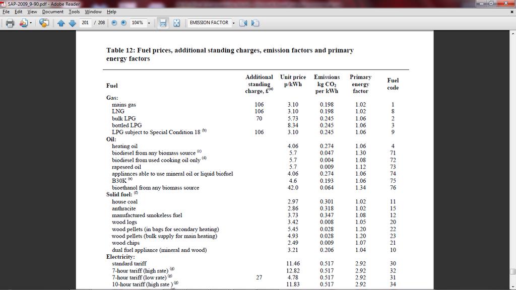
49 Factors