2015 ANNUAL ENGINEERING INSPECTION REPORT PLUM POINT ENERGY STATION CLASS 3N LANDFILL PERMIT NO S3N AFIN:
|
|
|
- Homer Neil McDaniel
- 5 years ago
- Views:
Transcription
1 2015 ANNUAL ENGINEERING INSPECTION REPORT PLUM POINT ENERGY STATION CLASS 3N LANDFILL PERMIT NO S3N AFIN: JANUARY 15, 2016
2 PLUM POINT ENERGY STATION CLASS 3N LANDFILL 2015 ANNUAL ENGINEERING INSPECTION REPORT PERMIT NO S3N AFIN: Prepared for Plum Point Services Company, LLC 2732 County Road 623 Osceola, AR Prepared by FTN Associates, Ltd. 3 Innwood Circle, Suite 220 Little Rock, AR FTN No. R January 15, 2016
3
4 January 15, 2016 TABLE OF CONTENTS PROFESSIONAL ENGINEER S CERTIFICATION... i 1.0 INTRODUCTION Purpose of Report Plum Point Energy Station Information Permit History LANDFILL LAYOUT Existing Conditions of Landfill Changes Made to Landfill Configuration During Reporting Period WASTE VOLUME CALCULATIONS ASSESSMENT OF LANDFILL FACILITY General Operations Landfill Cover System Leachate Collection System Stormwater Control System Facility Roads Fugitive Dust Control LIST OF APPENDICES APPENDIX A: APPENDIX B: APPENDIX C: Figures Copies of Weekly Landfill Inspections Photos of Annual Engineering Inspection LIST OF TABLES Table 3.1 Summary of waste volume calculations
5 January 15, INTRODUCTION 1.1 Purpose of Report The purpose of this report is to document the annual inspection of the Plum Point Energy Station (the Plant) landfill facility in accordance with 257, Subpart D - Standards for the Disposal of Coal Combustion Residuals (CCR) in Landfills and Surface Impoundments (the CCR Rule). In particular, the report has been prepared to comply with (b), which requires an inspection to be conducted by a qualified professional engineer to ensure that the design, construction, operation, and maintenance of the landfill is consistent with recognized and generally accepted good engineering standards. The report includes the following: Information on the current layout of the landfill, Waste volume estimates for the amount of waste contained in the landfill and remaining disposal capacity, and An assessment of the landfill including structural integrity and overall operations with respect to the CCR Rule and the facility permit requirements. 1.2 Plum Point Energy Station Information The Plum Point Services Company, LLC (PPSC) Plum Point Energy Station (the Plant, PPES) Class 3N Landfill (the Landfill) is located in Mississippi County, approximately 2 miles southeast of Osceola, Arkansas. The 245-acre solid waste management facility is located within the Plant boundaries. The location of the facility is shown on Figure 1 (all figures are located in Appendix A). The site is characterized by flat terrain and is situated within the Mississippi River floodplain. The Plant is located in an agricultural and industrial area. PPSC is the owner of the landfill facility but uses a contractor to operate the Landfill for disposal of CCR materials generated at the Plant and general maintenance of the landfill facility. The Plant generates electricity through the combustion of coal, which produces CCR materials that are captured through the facility air emission control systems and placed in the 1-1
6 January 15, 2016 onsite landfill. The CCRs consist of bottom ash, economizer ash, fly ash, and coal pulverizer rejects. The bottom ash is the coarsest fraction of the coal ash and is collected in a water-filled trough beneath the steam generation furnace. Bottom ash is composed of angular, glassy particles with a porous surface texture and has the consistency of coarse sand. Coal pulverizer rejects are periodically sluiced to the collection trough beneath the boiler furnaces along with the bottom ash. The economizer ash is the heavier fraction of fly ash and is collected in hoppers and is periodically transferred via dry flight conveyors to a submerged flight conveyor that carries the bottom ash, economizer ash, and coal pulverizer rejects to a concrete basin called the Bottom Ash Stockout Area. The collected materials are periodically loaded into haul trucks and taken to the Landfill. The largest fraction of the CCR material generated from the coal combustion process is fly ash. The fly ash is composed of very fine particles similar to glass and has the consistency of a powder. The plant has a fly ash collection system that captures dry air heater ash and dry scrubber ash in a series of fabric filter and air heater hoppers. The collected material is conveyed to a large silo, which is periodically unloaded into haul trucks and transferred to the Landfill. The Plant air emission controls include a dry Flue Gas Desulfurization (FGD) system and an activated carbon injection system. The FGD system is designed to cool down the flue gas and remove sulfur dioxide and particulate matter from the gases emitted from the coal-fired boiler. This is accomplished by a chemical reaction using a slurry of calcium hydroxide with the flue gases, while simultaneously allowing the hot flue gases to dry the reaction products (calcium sulfite, calcium sulfate, calcium chloride, and calcium fluoride). The dry reaction products are collected with the fly ash materials in a fabric filter hopper system. The activated carbon injection system removes mercury from the gases emitted from the coal-fired boiler. The mercury combines chemically with powdered activated carbon and is removed in the same filter system as the fly ash and dry scrubber ash. The used FGD lime slurry is collected and reused within the FGD system. The retained solids are containerized and periodically transported to the Ash Containment Area, and then to the onsite landfill. 1-2
7 January 15, 2016 Water is pumped from the Mississippi River and clarified to become either cooling tower makeup water or service water for plant use. The sludge generated from this process is conveyed to a filter press where the solids are containerized and periodically transported to the onsite landfill. The filtrate from this process is pumped back to the clarifiers for treatment. Although it varies greatly, the Plant generates approximately 500,000 tons of fly ash, bottom ash, and filter cake per year, of which approximately 85% is fly ash, 10% is bottom ash, and 5% is filter cake. The amount placed in the Landfill also varies from year to year, but the average for the past 5 years is approximately 150,000 cubic yards (cy), in-place volume. The permitted landfill area is located west of the plant site as shown on Figure 2. The landfill is permitted to have 12 disposal areas, varying in size from 15 to 9 acres. 1.3 Permit History In July 2001, Genesis Environmental Consulting, Inc. (GEC) submitted an application on behalf of Plum Point Energy Associates, LLC, to the Arkansas Department of Environmental Quality (ADEQ) for a solid waste disposal facility at the PPES. In October 2002, ADEQ issued a solid waste permit (0303-S3N) to construct and operate the proposed Class 3N facility. Prior to construction of the landfill, GEC submitted a minor permit modification application in November 2005 to revise the final landfill grading plan, stormwater control plan, bottom grading plan, earthwork balance calculations, and Construction Quality Assurance (CQA) Plan. The application also included the request for an alternative bottom liner design. ADEQ requested the inclusion of a leachate collection system and Terracon Consultants, Inc. (which had purchased GEC) submitted revised permit documents in July ADEQ approved the minor permit modification in September Cell 1 of the landfill and the western stormwater pond were constructed in The Plant and the Landfill began operation in March Since beginning operation, the landfill constructed an adjacent cell, Cell 3, in 2014 and began placing waste in the new cell in
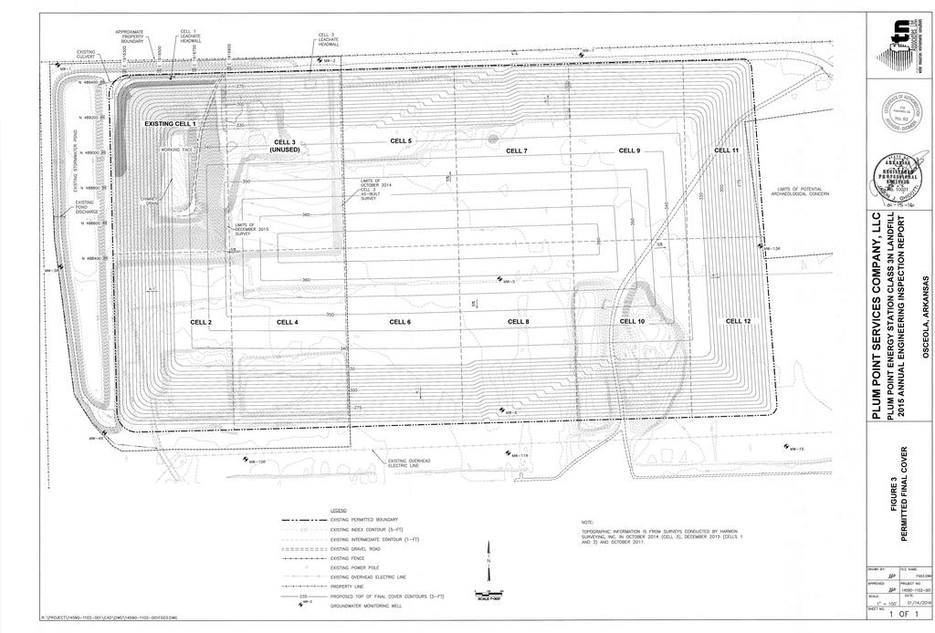
8 January 15, LANDFILL LAYOUT 2.1 Existing Conditions of Landfill The PPES Class 3N Landfill is approximately 173 acres in size and has been designed to have 12 waste disposal cells (Figure 1, Appendix A). Cells 1 through 10 are about 15 acres in size with approximate dimensions of 1,000 ft by 660 ft. Cells 11 and 12 are narrower and smaller than the remaining cells to accommodate a potential archeological concern located east of the Landfill. Cell 11 is about 9.6 acres (450 ft by 1,000 ft) and Cell 12 is about 10.8 acres (500 ft by 1,000 ft). The permitted disposal capacity (air space) is 22,400,000 cubic yards. The Landfill has been designed to meet Arkansas Pollution Control and Ecology Commission Regulation No. 22 standards. The bottom of the Landfill is divided to slope north or south to leachate collection sumps. The elevation of the bottom varies from 245 ft National Geodetic Vertical Datum (NGVD) in the center of the Landfill to 230 ft NGVD at the collection sump. The final surface of the Landfill has 4:1 (horizontal to vertical) slopes up to elevation 335 ft NGVD and then slopes at 5% to elevation 365 ft NGVD (Figure 3). The bottom liner system for Waste Cells 1 and 3 were prepared in accordance with the 2002 permit for the facility (i.e., 12-inch minimum thickness compacted clay liner with a maximum hydraulic conductivity of 1 x 10⁻⁷ cm/sec, a 60-mil HDPE liner and a leachate collection system). No final cover system has been installed on Waste Cells 1 and 3. However, as shown on Figure 1, the west, north, and south slopes of Cell 1 have received interim soil cover. 2.2 Changes Made to Landfill Configuration During Reporting Period During 2015, the facility began utilization of the new Cell 3, which will eventually allow waste to be placed at higher elevations in the adjacent Cell 1, increasing its operational capacity. The landfill manager that works for the contracted landfill management company, Charah, reported additional improvements during the year. Of note is installation of a new leachate forcemain from Cell 1 to the onsite collection tanks. 2-1
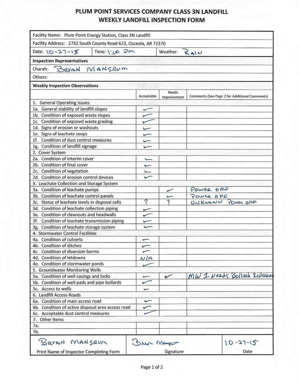
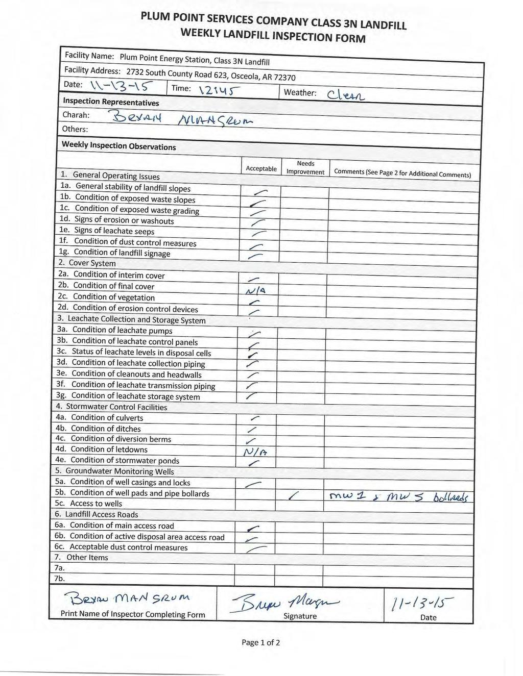
9 January 15, 2016 To prepare for the new CCR rule, Charah staff that are responsible for the landfill facility were trained on conducting weekly inspections, copies of which are included in Appendix B. The inspections began in October 2015 in accordance with the CCR Rule. It appears that the inspections these were done by the same inspector from Charah during October, November and December. It is recommended that the inspector be alternated and inspections reviewed by all necessary personnel. 2-2
10 January 15, WASTE VOLUME CALCULATIONS The landfill facility has been surveyed annually since Each year s survey is compared to the previous year to compute the amount of CCR disposed. The current survey is also compared to the permitted top of waste elevations to determine remaining capacity, or airspace. Additionally, the current survey is compared to an estimated operational top of waste to determine the remaining operational capacity. The operational top of waste is the maximum disposal elevation that can be achieved within the open cells while maintaining the required 4:1 exterior and 3:1 interior slopes along with a top width sufficient for disposal activities. If additional operational capacity is needed, construction of an adjacent disposal cell will be required. Disposal rates for the facility are calculated using the average of the disposal rates from the five most recent years. Disposal rates depend upon CCR production at the plant and sales of the ash, if any. These can vary significantly year to year based upon the current economic climate, weather, and how much the plant is operational. For the reporting year of 2015, the active disposal areas of the landfill were surveyed on May 7, 2015 and again on December 22, 2015, a period of approximately eight months. A comparison of surface models developed from these surveys as well as the operational top of waste is summarized in Table 3.1, below. Current disposal activities resulted in a net fill of approximately 87,600 cubic yards of ash in the active disposal area during the eight-month period. 3-1
11 January 15, 2016 Cell Number Status Area (ac) Table 3.1 Summary of waste volume calculations. Permitted Waste Capacity (cy) 2015 Volume Placed* (cy) Total Volume Placed (cy) Operational Remaining Disposal Capacity (cy) Operational Remaining Life (years) Cell 1 Active ,607,400 20, , , Cell 3 Active ,191,700 66,660 66,700 1,142, Totals ,799,100 87, ,900 1,425, * Volume filled during the 8-month period of May through December The 5-year average disposal rate, including 2015, is approximately 153,000 cubic yards per year, in-place volume. At this rate, the calculated available airspace, 1,425,200 cubic yards, provides approximately 9 years of remaining operation capacity before a new disposal cell must be opened. 3-2
12 January 15, ASSESSMENT OF LANDFILL FACILITY This section of the report provides a summary of the inspection of the Plum Point Landfill facility that was conducted on December 17, The assessment included an interview with the landfill operating company (Charah) personnel, review of weekly inspections of the facility, review of documents pertaining to the operation and compliance of the landfill, and an onsite inspection of the landfill facility. Copies of the Weekly Inspection Reports are included in Appendix B. Photographs of the site inspection are included in Appendix C. 4.1 General Operations Active disposal during 2015 was conducted primarily at the top of Cell 1 and proceeding east into Cell 3. The side-slopes of the landfill are generally at the required 4:1 external and 3:1 interior slope requirements. Much of the western, northern, and southern slopes of Cell 1 have been covered with interim soil cover and are well vegetated. The elevated disposal area in Cell 1 is surrounded by berms for safety and to reduce effects of wind, as described in Section 4.7, below. It appears that some sections of these berms have been raised as the level of ash in the active areas rises. This has created steeper slopes near the top of the side slopes of the landfill. These were noted to the landfill manager who will regrade the affected upper slopes as soon as weather conditions allow. Charah also plans to place interim cover on these slopes, once graded. No tension cracks, seeps, or other features that indicate a potential slope failure were observed during the site inspection. In addition, no active seeps were noted on the exterior slopes. The general operations of the landfill facility are being done in a safe manner and the overall maintenance of the facility is in good condition. 4-1
13 January 15, Landfill Cover System As noted, no final cover system has been installed on Waste Cells 1 and 3. Figure 3 presents contours for the currently permitted final cover system. Both active cells remain open. Interim cover soil has been placed, as noted, on the western, southern and northern side slopes of Cell 1. The landfill manager plans to begin installation of additional interim cover in Leachate Collection System Waste Cells 1 and 3 do have leachate collection systems. The cells are graded to drain to sumps in each cell from which leachate is pumped via dual-contained transmission lines to onsite storage tanks. From there the leachate is recirculated to the active cells for dust control or is loaded to trucks for reuse in the Plant's FGD lime slurry system or disposal at an offsite treatment facility. Improvements were made to the leachate transmission lines during 2015 to increase pumping efficiencies. 4.4 Stormwater Control System Stormwater at the landfill site flows west to the stormwater pond on the western side of Cell 1. To prevent run-on, a stormwater channel and berm was constructed along the north side of the landfill, routing stormwater west around the landfill. Additionally, clay perimeter berms prevent both run-on and run-off. Stormwater from the covered slopes drains to the onsite stormwater pond located west of Cell 1. Stormwater channels, culverts and discharge structures were in good operational condition. The facility is permitted to discharge stormwater under NPDES General Landfill Stormwater Permit No. ARG160042, as issued by the ADEQ effective April 30, 2009, and renewed March 1, Facility Roads Facility perimeter and access roads were generally well maintained and allow all-weather access. 4-2
14 January 15, Fugitive Dust Control The facility is operated as outlined by the CCR Fugitive Dust Control Plan, prepared in October Fly ash is transported to the landfill using end-dump trucks with tarps. The ash is mixed with water in the pug mill at an appropriate ration to minimize fugitive dust problems during truck loading and dumping, but not create excess free liquids. Water is applied, when necessary, for dust suppression on roads and the landfill using a water truck. Speed limit signs were posted along the main haul road to the Landfill. 4-3
15 APPENDIX A Figures
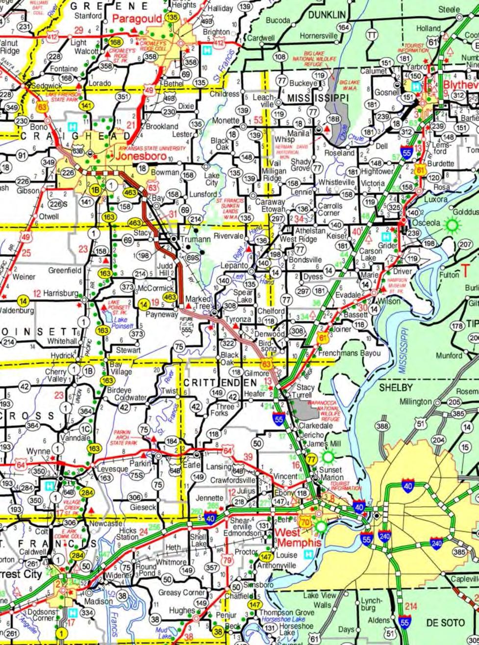
16 PROJECT LOCATION R:\projects\ \cad\dwg\ FG01 Figure 1. Site location map.
17
18
19 APPENDIX B Copies of Weekly Landfill Inspections

20
21
22
23
24
25
26
27
28
29
30
31
32
33
34
35
36
37
38
39
40
41
42
43
44
45 APPENDIX C Photos of Annual Engineering Inspection


46 Photo 1: Cell 3 disposal area, Cell 1 from east Photo 2: Cell 3 active disposal area, Cell 1 from east


47 Photo 6: Side slope of landfill, typical of north and west sides of Cell 1 Photo 7: Upper section of Cell 1 west slope, above interim cover


48 Photo 8: Top of Cell 1, edge berms and chimney drain Photo 9: Cell 3 northwest chimney drain


49 Photo 10: Cell 3 stormwater separation berm, from east Photo 11: Typical leachate pumping system, Cell 1


50 Photo 3: Typical 'Limit of Waste' and Edge of Liner signage Photo 4: Leachate storage tanks

51 Photo 5: Stormwater pond from Northeast