Design Optimisation and Characterisation of a Crossflow Turbine
|
|
|
- Aldous Skinner
- 5 years ago
- Views:
Transcription
1 Design Optimisation and Characterisation of a Crossflow Turbine By C.S. Kaunda University of Dar es Salaam/NTNU 02 nd May, 2012 Supervisors Prof. Kimambo - UDSM Prof. Nielsen - NTNU
2 Outline of Paper Presentation Introduction: Link between energy and development: Scenario in sub-saharan Africa (SSA) Rural Electricity Supply Scenario in SSA Microhydropower Technology Status, Potential in and Challenges in SSA Crossflow Turbine Technology and Microhydropower in SSA Performance Challenges of Crossflow Turbines Areas of Improvement Conclusions
3 Energy and Development Modern energy supply such as electricity supports achievement of MDGs. Social and economic as well as environmental management activities are supported by sustainable energy supply SSA (except South Africa) faces acute shortage of modern energy. Electricity scenario in most countries is characterized by low consumption, small generation capacity/million people, unreliability of power supply and low electricity supply levels.
4 Region Electricity access in Regional aggregates (IEA, 2010) Population without electricity millions Electrificatio n rate % Urban electrificatio n rate % Rural electrificatio n rate % Africa North Africa Sub-Saharan Africa Developing Asia China & East Asia South Asia Latin America Middle East Developing countries 1, World* 1,
5 Electricity Consumption Levels (World Bank, 2009) Sub-Saharan Africa Electricity Consumption Level (kwh/capita) Electricity Consumption Level (kwh/capita)
6 Electricity Access Levels in Southern Africa in 2005 (World Bank, 2008) (c) Electricity Access Levels in Southern Africa (2005) Urban Electricity Access Level (%) Rural Electricity Access Level (%) Angola Botswana DRC Lesotho Malawi Mozambique Namibia South Africa Zambia Zimbabwe
7 Microhydropower Technology Hydropower technology using small-scale plants is well matured (Khennas and Barnett, 2000; Kaldellis et al, 2005) and has been in use for many years ago. Microhydropower is a subset in Small Hydropower (SHP) categorization: No international agreement upper level of SHP. Most EU (10 MW), SA (10 MW), USA (30MW), Brazil (30 MW), China (50 MW) Microhydropower (MHP): Less than 100 kw mostly. MHP used for both: electricity generation and mechanical power. In SSA, technology brought by missionaries and early tea planters. Ideal for rural electrification: rural institutional facilities such as schools, health centres and markets Considered renewable, but climate change (droughts and desertification) affects MHP availability during particular months of the year.
8 MHP Potential in SSA Country Identified Potential Declaration of Source Malawi 7.4 MW Kaunda and Kimambo, 2011 Tanzania 185 MW Kabaka and Gwang ombe, 2007 Mozambique Over 1000 MW Hankins, 2009 Zimbabwe 120 MW Government of Zimbabwe, 2009 Rwanda Over 300 sites identified. Rwanda Utilities Regulatory Total power potential not Agency, 2009 known Ghana 21 sites identified with power potential ranging from 4 to 325 kw Government of Ghana, 2010 Kenya Over 3000 MW Government of Kenya, 2011 Uganda 210 MW Uganda Energy Regulatory Authority, 2007 Nigeria Over 3500 MW Sambo, 2009
9 MHP Application status in SSA Country SHP Installed Capacity Declaration of Source Ethiopia 80 MW In Conference Proceedings: Ministerial Conference on Water for Agriculture and Energy, Libya, Kenya 15 MW Kipyego, 2011 Uganda 18 MW Uganda Electricity Regulatory Agency, 2009 Rwanda 6.5 MW Rwanda Utilities Regulatory Agency, 2009 Tanzania 5.4 MW Kaunda et al, South Africa 68 MW Renewable Energy in emerging and developing countries Project: Country Report, South Africa, 2006 Malawi 1.3 MW Kaunda and Kimambo, 2011 Zimbabwe 1.4 MW Tinarwo, 2009

10 Basic components and arrangement of a typical micro hydropower system, RoR Weir Penstock Forebay Power canal Main River Tail race water Transmission system to Load Power house Electromechanical system
11 MHP Mechanical Power Generating equipment - Turbine Grouped into Reaction & Impulse turbines Can be low, medium and high head Francis, Kaplan, Propeller are reaction types Pelton Wheel, Turgo and Crossflow? Are impulse type Efficiencies high except Crossflow
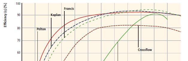
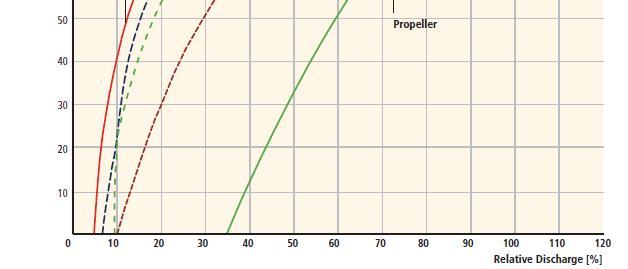
12 Turbine Performance Curves (IPCC, 2011)

")
13 Crossflow Turbine Application range in MHP (Southeast Power Ltd, 2008)
14 Crossflow Turbine (CFT) Relatively cheap as compared to others: per kw of installed capacity, CFT has lower cost. CFT runner relatively simple to manufacture most of the local workshops in developing countries have facilities to fabricate one. CFT Impulse type of turbine as such able to handle poor water quality in power production CFT has ability to maintain optimum efficiency levels for a varied flow CFT Common in developing countries S.E Asia (India, Nepal, Afghanistan et al). CFT Technology is now becoming popular in some SSA countries such TZ and MW. In TZ, most of the recorded MHP are of CFT. In Tanzania, UDSM, Arusha technical college are involved in the fabrication of the technology. In Malawi, The Polytechnic and Malawi Industrial Research and Technology Development Centre also involved in the fabrication.

15 Crossflow turbine Nozzle Runner Guide vane Draft tube


16 Crossflow Turbine Runner Runner blades Bearing housing Shaft
17 Crossflow Turbine (CFT) Due to its low efficiency levels, most of the turbine manufacturing companies did not embark on improving its performance studies for wide scale application. Performance studies on the CFT are relatively few compared to other types of turbines: CFT are less efficient turbines (less than 80% practically possible) CFT poor performance is due to poor its poor internal flow profile in the runner. Studies concentrated on optimising the geometric dimensions of physical design parameters and varying performance.
18 Crossflow Turbine (CFT) In the design and optimization of the turbine, it is important to evaluate : How does the internal flow pattern affect the hydraulic efficiency in the turbine? How does the fluid velocity and pressure distribution influence the turbine performance for a given flow and head? What are the effects of changing geometric design parameters to the turbine performance?
19 Crossflow Turbine (CFT) Flow profile can be characterized using Navier- Stokes equations Flow in CFT is quite complex, 3d-dimensiona; and two phase. Characterization and design optimization done by using CFD.
20 CFD Design Procedure
21 Conclusions Capacity for CFT to be used in rural electricity supply is high in SSA Need to look at addressing technological issues that hinder MHP development in the region. In this case supporting local turbine manufactures with efficient design models will help. CFT design need to be looked at optimization the internal flow profile. This may define the optimum size of the turbine for particular site (head and flow rate) and flow conditions.
22 Thank you for listening