The course of Pump and Hydropower systems has features dedicated to the framework of the project activity
|
|
|
- Joshua Holland
- 5 years ago
- Views:
Transcription
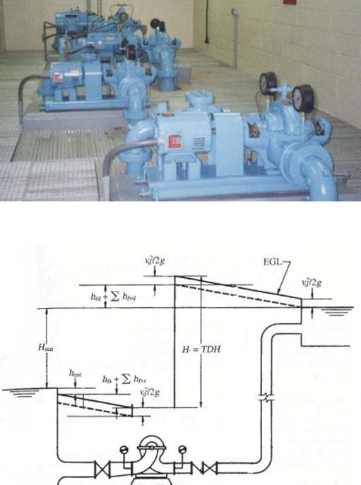
1 The course of Pump and Hydropower systems has features dedicated to the framework of the project activity 1- Fundaments These systems are for: Supply energy or hydraulic load needs, in order to allow transport fluids and their use in conditions considered appropriate or desired - pumping systems. - harnessing excess of energy or hydraulic load for the production of energy in an economic way and profitable, and technically useful by transforming energy of the fluid into hydropower systems. There are systems which can be alternately pump systems and hydro for a certain period of the day and pumping other periods. 2- Pump systems The pump systems are hydraulic systems in pressure where the elevation is provided power line through a specific component, the hydraulic pump. The hydraulic pump receives power from the outside, namely electrical energy transformed into energy mechanically by a motor, and gives it to the flow. Thus, the hydraulic load flow (energy per unit weight of fluid) is raised. The resulting hydraulic head enables: overcoming hydraulic resistance to flow - to compensate the hydraulic losses o the system compatible with the physical characteristics and the flow that is intended to drain; overcoming unfavorable topographic gap - raise the fluid topographic quota from the source (upstream) to a higher topographic elevation at the destination (downstream); ensure minimal pressure when considered in fluid sections of the supply system for the intended applications.
2 Hydraulic load, H A hydraulic pump or a group of hydraulic pumps allows lifting the Hydraulic load H of Section 1 (upstream) and section 2 (downstream): The steady state conditions (no change in the time domain) to increase the energy grade line, or increase of hydraulic load corresponds to a transfer of energy from an outside source. The ceded energy per unit of time corresponds to the input power set of hydraulic pumps: Power = γ Q H / η being γ = unit weight of the fluid; Q = total flow rate of the fluid flow; H = hydraulic load supplied to the flow through hydraulic pumps; η = total efficiency of motor-pump groups and the transfer process of energy. The amount of energy supplied from the outside for a time interval T corresponds to the integral value as follows:
3 Typologies
4

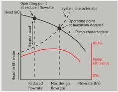
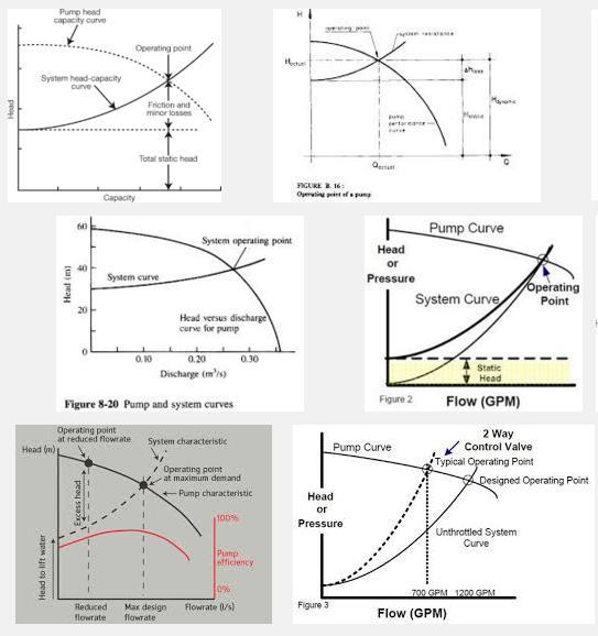
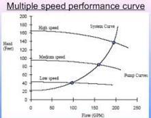
5 Pump and system characteristic curves
6
7
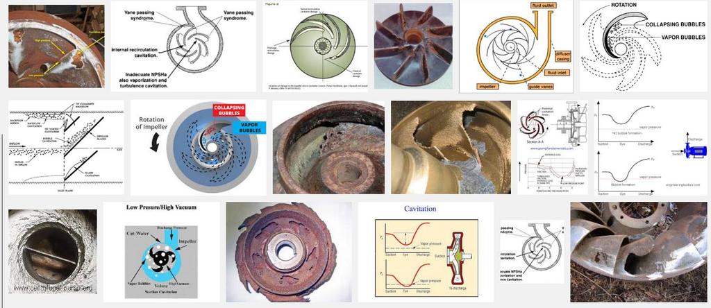
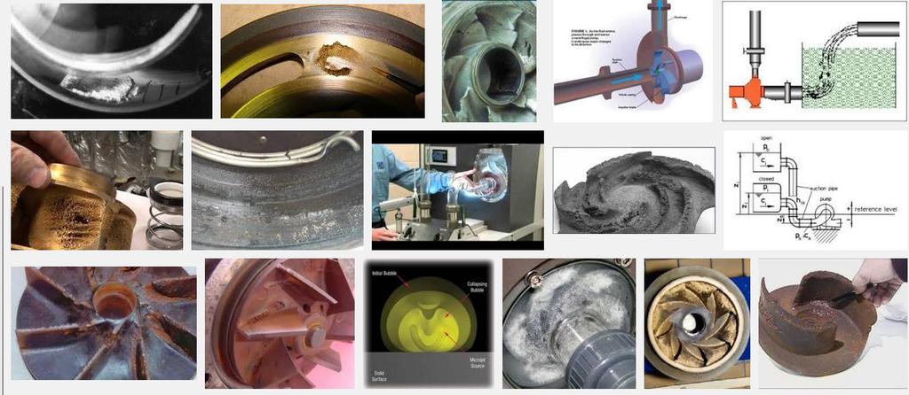
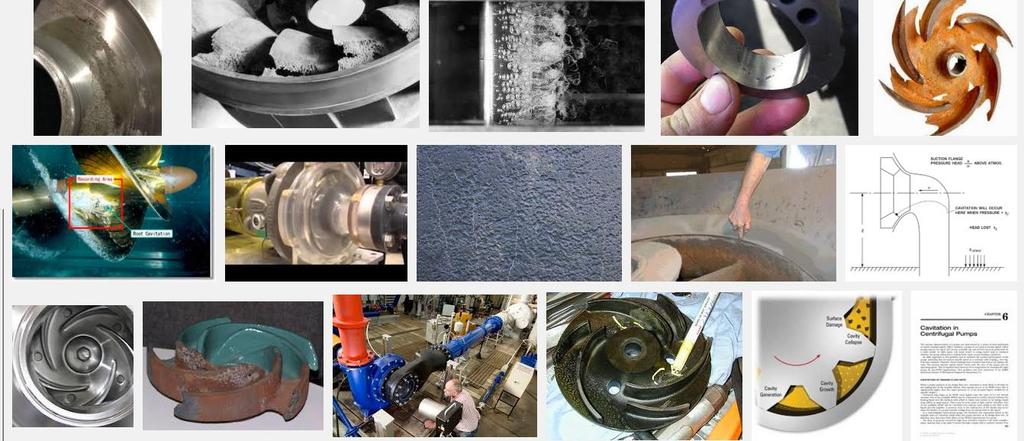
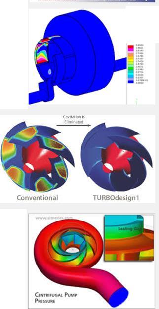
8 Cavitation When the low pressure reaches the liquid vapor pressure. Bulbous nuclei grow and be swept downstream where the pressure is higher leads to the collapse of these vapor pockets causing noise, vibration, erosion and disruption of the pipe system. For pumps the parameter for cavitation is NPSH (net pressure suction head). Required NPSH is the minimum difference allowed between absolute piezometric high at pump entrance and the vapor pressure. For good operating conditions the NPSH available in the hydraulic system must be greater or equal the NPSH required by the pump. The suction head hs is:
9
10
11
12
13 Types of pumps Minimum volume of the suction tank The classic formula which results from the maximizing starts frequency value of a hydraulic pump achieves the minimum usable volume suction tank due to the time between starts: V=Qb T/4 being V = net volume (m3) Qb = pump flow rate (m 3 /s) T = time interval between start times of the hydraulic pump (s) This value V corresponds to Qb= 2Qa, with Qa the inflow to a supposed constant tank.
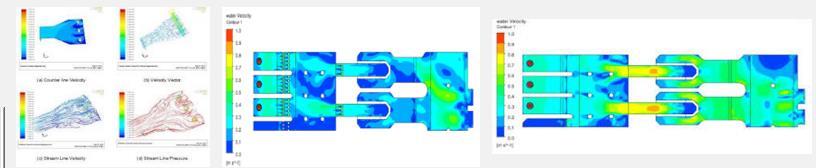
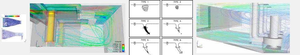
14 You may need to consider another conditioning: the maximum detention time (Tdmax): The Qb flow rate (pumping capacity) should not be less than the inflow Qa. The maximum starting frequency may be of the order 15 starts per hour. Example of suction tank The supply of the suction pipes from bypass channels or suction tanks is associated with some special hydraulic problems, associated with the formation of vortices. These problems are characterized basically by possible appearance of vortices in the zone near the inlet section of the suction pipe.

 and may cause vibrations.")
15 The vortices formed within the flow with free surface, immediately upstream of the suction section can be drawn into the duct by establishing then a potential route of air suction between the free surface and inside the hydraulic circuit. The inlet pressure in the hydraulic circuit is very inconvenient: the air can storage at high points to be gas pockets that reduce the flow capacity (induction loss of hydraulic head) and may cause vibrations. The air intake in the hydraulic machine (pump) may seriously disrupt the functioning of them (reduced income and vibrations).
16
 can cause: - air intake and hydropneumatic effects; - disruptions in the operation of")
; - increased localized pressure losses; - possibility of introducing objects or debris by")
17 In summary, the formation of vortices in the suction zone of the pump or water intake (at inlet) can cause: - air intake and hydropneumatic effects; - disruptions in the operation of hydraulic machines (reduced values of efficiencies, increased NPSH, vibration and noise...); - increased localized pressure losses; - possibility of introducing objects or debris by suction.