Coldwater WWTP MWEA Process Seminar. Ammonia Polishing with IFAS and High Speed Turbocompressors at Coldwater WWTP 11/2/2011
|
|
|
- Esther Craig
- 5 years ago
- Views:
Transcription
1 Fishbeck, Thompson, Carr & Huber, Inc MWEA Process Seminar Ammonia Polishing with IFAS and High Speed Turbocompressors at Coldwater WWTP Jim Flamming, P.E., Senior Process Engineer, FTC&H Coldwater WWTP Coldwater, Michigan, USA Owned by Coldwater BPU Average flow: 3.2 mgd Peak flow: 8 mgd BOD, TSS, ammonia, phosphorus, and pathogen removal Surface water discharge Treats residential, commercial, some industrial, plus septage 1
2 Coldwater WWTP Background New discharge permit issued August 2007 Included seasonal ammonia limits 2 mg/l from May through November Previously was report only Routine violations through spring and summer 2008 CBPU hired FTC&H to investigate possible solutions 2

3 Combined Biological Treatment Processes Pair fixed film and conventional activated sludge Done for decades in municipal WWTPs Offers advantages of both processes, minimizes disadvantages Fixed Film energy efficient, stable, resistant to shock loads Activated Sludge improved settling characteristics, higher effluent quality Systems can be combined in several different ways Trickling Filter Solids Contact Process TF/SC Trickling Filter Aeration Basin Secondary Clarifier Combines trickling filter with relatively small activated sludge basin Majority of BOD removal done in trickling filter low to moderate loading rates Activated sludge has low HRT, used for polishing 3
4 TF/SC Design Criteria Design manuals list typical design criteria* Trickling filters: BOD loading rates: lb/day/1,000 cu ft of filter media/day Aeration Basins: HRTs: hrs (10-15% of strictly AS alone) MCRTs: days F/Ms vary widely: At low TF loading rates, process is capable of nitrification, though achieving consistent results can be difficult due to the nature of the TF process * - WEF, 2000; WEF/ASCE, 1998; Metcalf & Eddy, 2003 Nitrification in TF/SC Process To achieve higher levels of nitrification, add: Intermediate clarifiers downstream of TFs to reduce organic loads on SCs Solids reaeration basins to increase MCRT and inventory of nitrifiers; called TF/SC-R process Regardless of configuration, nitrifying in TFs can significantly reduce volume and aeration required for nitrification in subsequent aeration basins IFAS media could also be used to increase nitrification capacity in SC basins of TF/SCs if other modifications are not feasible; creating a TF/SC-IFAS system 4
5 Engineering Review and Problem Solving Coldwater TF/SC process Three, 115 ft dia TFs filled with 7 ft of cross flow plastic media Followed by two parallel 152,000 gallon solids contact aeration basins (each 70 X 20 X 14.5 deep) Low TF BOD loading rates: Average 10.5 lb/day/1,000 cu ft Maximum 44.8 lb/day/1,000 cu ft Minimum 1.1 lb/day/1,000 cu ft Significant but inconsistent nitrification observed in TFs Engineering Review and Problem Solving Expansion of aeration basins difficult due to high groundwater level at the site. Evaluated expanding the trickling filters Discussed options with Brentwood Industries Concrete tanks with aluminum domes 4th trickling filter would be expensive Investigated potential for upgrading aeration basins with IFAS media 5
")
6 IFAS Systems Suspended media Poured into aeration basin Moves freely in mixed liquor Retained in basin typically with in-basin screens Various manufacturers IFAS Systems AccuFAS IFAS (Brentwood Industries) 6
7 BioWin Modeling TF Effluent Aeration Basin Effluent Sludge Used to size aeration requirements and predict effluent quality under various flow scenarios. Both basins in operation One aeration grid out of service One basin in operation, one out of service Modeling showed aeration expansion required Types of Aeration Blowers Aeration consumes 40-70% of energy used in activated sludge plants (WEF MOP OM-9) For supplying diffused aeration grids, 2 types: Positive Displacement Approx. 60% efficient Typically smaller (<100 hp) Output varies with speed, not pressure Factory or OEM packages available Widely applied, low capital costs 7
8 Types of Aeration Blowers Multistage Centrifugal: Approx % efficient Wide range of sizes, typ. >50 hp Output varies with pressure Widely applied for over 100 yrs. Can be more expensive initially than positive displacement PD and multistage blowers are the workhorses of the industry. Times Are Changing! With renewed emphasis on energy efficiency, new styles of blowers are starting to be applied. High speed turbocompressors offer several potential advantages over traditional blowers: Higher efficiencies Lower maintenance costs Variable output Quiet operation 8

9 High Speed Turbocompressors Operate at very high speeds: 25,000 to 45,000 rpm No contact bearing surface: magnetic or airfoil bearings No contact = no friction = no wear parts Oil free operation; no lubrication required or bearings to service Very low maintenance High Speed Turbocompressors 10-20% improvement in efficiency Operate on VFDs; maintaining best efficiency at turndowns of up to 50% of max output No contact very low vibrations low noise (<70 db at op. speed) Factory supplied pkg units w/ controls Typ. small footprints 9

10 High Speed Turbocompressors Different styles from different manufacturers Magnetic Bearings ABS/HST, Hoffman Revolution, Atlas Copco ZB-VSD; Spencer AyrJet Air Foil Bearings HIS HT; APG-Neuros; Turblex; Aerzen; Howden Magnetic bearings prevent any contact during operation, but typically cost more upfront Most are direct drive units; Turblex also provides a separately geared unit with additional control capability ABS/HST Five models HP ,400 scfm psig discharge pressure 10

11 Coldwater WWTP Existing plant had two 75-hp, 900-scfm blowers Biowin model showed system required a firm capacity of 3,260 scfm. Installed two 93-hp ABS/HST S A-5; each 1,257 scfm at 8 psig Placed in new building; existing blowers remain as backup units City doesn t have historical flow and hp draw data for blowers; difficult to compare Final Design 11
12 Final Design Final Design 12
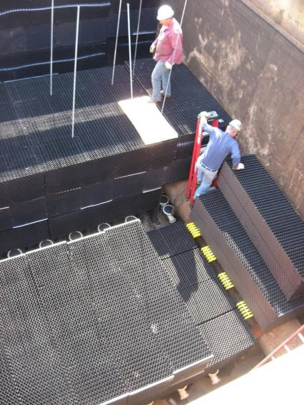


13 Installation Installation 13


14 Installation Installation 14
15 Results Secondary effluent > discharge limit 60 times before IFAS Secondary effluent > discharge limit 43 times after IFAS startup 41 of those times were as a result of industrial plant failure Results 15

16 Summary IFAS can be applied to existing TF/SCs and other plants to increase sludge age and total inventory of nitrifiers, without increasing loads to secondary clafifiers, and reduce effluent ammonia concentrations. High-speed turbocompressors offer improved efficiency over other aeration blowers. Fishbeck, Thompson, Carr & Huber, Inc. Any Questions? THANK YOU! 16