Afon Claerwen Hydropower Project. Flood Risk Assessment. February 2018
|
|
|
- Edith Jordan
- 5 years ago
- Views:
Transcription


1 Afon Claerwen Hydropower Project Flood Risk Assessment February 2018 Hydropower Consultancy & Development
2 Document Control Scheme Name: Client Name: Client Address: Afon Claerwen Hydropower Project Elan Hydro Ltd Ellergreen Hydro Ltd Reference: YTFH Ellergreen Hydro Ltd Ellergreen Estate Office Hollins Lane Burneside Kendal Cumbria LA9 5SD Tel: Web: Ellergreen Hydro Ltd Pod 3 Avon House 19 Stanwell Rd Penarth Vale of Glamorgan CF64 2EZ Tel: Web: Document Control File Name: Original Rev A Prepared by: Approved by: ACEV-DOC--A ARC Original Rev Revision C A A. Copper A. Cropper Date: Status: Approved Revision D Comments: Disclaimer This report, and information or advice which it contains, is provided by EGH Ltd solely for internal use and reliance by its Client in performance of EGH Ltd s duties and liabilities under its contract with the client. Any advice or recommendations within this report should be read and relied upon only in the context of the reports as a whole. The advice and opinions in this report are based upon information available to EGH Ltd at the date of this report and may be based on assumptions. Following final delivery of this report to the Client, EGH Ltd will have no further obligation or duty to advise the Client on any matters, including development affecting the information or advice provided in this report. This report has been produced by EGH Ltd in the professional capacity as Consulting Engineers. The content of this report do not, in any way, purport to include any manner of legal advice or opinion. EGH Ltd accepts no responsibility or liability for any loss or damage incurred due to the use of the information within this report. Page 1
3 CONTENTS 1. INTRODUCTION FLOOD FLOWS FLOOD ZONES INFRASTRUCTURE Intake Road... Error! Bookmark not defined. 4.3 Powerhouse FLOOD PROTECTION FLOOD RISK AS A CONSEQUENCE OF THIS DEVELOPMENT Consequence of abstraction Consequence of malfunction CONCLUSIONS... 9 Page 2

4 1. Introduction This document presents a flood risk assessment of the site of a proposed new hydro scheme on Afon Claerwen, Elan Valley, Powys. This assessment takes into account the advice set out by the Welsh Assembly Government in Planning Policy Wales Technical Advice Note 15 Development and Flood Risk. 2. Flood Flows The flow regime of Aflon Claerwen is affected by Claerwen Dam, storing flood flows in the reservoir acts to smooth the flood events of the watercourse. How effectiverly a dam attenuates a watercourse is dependant on its overspill design and dimensions. The Clearwen dam spans 310m of which approximately 190m is spillway. Page 3
 the spillway is large and therefore the attenuation will be moderate but not insignificant during a record precipitation event.")
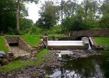
5 Figure 1 & 2 Claerwen Dam in overspill scenario during moderately high flows In respect to the catchment size of the watercourse (69km2) and the area of the reservoir (2.3km2) the spillway is large and therefore the attenuation will be moderate but not insignificant during a record precipitation event. Low Flows has been run on the watercourse at the proposed hydro projects intake locations at NGR SN and the Q0.1 percentile figure is 37.57m3/s. With the dam and this result in mind the 1 in 100 year flood event can be estimated as 100m3/s. This should be further increased due to the unknown but significant effects of climate change and therefore a flow of 125m3/s has been used for the purposed of this flood risk assessment. Records of flood levels are not available for Clearwen Dam or watercourse but records from Lyne Brianne dam are an interesting comparison. The highest recorded flood since the Lyne Brianne Dam was constructed (which also similarly attenuates any flood) occurred on 18/10/1987 and was a flow of 67.17m 3 /s. The catchment of the Tywi at Lyne Brianne is 89km2 so over 25% larger than the Clearwen. This helps gives some assurance on the chosen flood flow of 125m3/s for Clearwen. 3. Flood Zones Both the intake and the powerhouse sit within the high risk flood zones. Page 4

6 Figure 3 NRW flood zone map F Figure 3 NRW Flood Risk Zones Figure 4 NRW flood zone for reservoir flooding Page 5

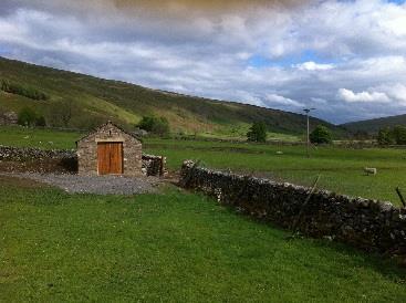
7 4. Infrastructure 4.1 Intake The intake is located in an area of open moorland without any nearby dwellings. This also remains the case upstream of the intake in the vicinity of the watercourse. The intake is a reinforced concrete structure designed to operate under submerged conditions with wing walls at 303mAOD. The weir structure has a weir crest (302.00mAOD) only a small amount above that of the natural bed, therefore creating an elevated water level extending only a short distance (38m) upstream before the natural water level resumes due to the increasing elevation of the bed topography. Figure 3 Ponded section in mid-range flows During an extreme flood event the entire intake weir along with wingwalls are submerged. This has no detrimental effect with all parts and materials designed to be without detriment in this scenario. The ponding during an extreme flood event is not extended, in fact the upstream of the weir will no longer be a ponded area in a flood flow, the watercourse being fast flowing and riffle over the submerged intake. The banks are being restored at the unaltered elevations as present with the low lying intake chamber on the South side of the watercourse being built into the bank rather than extending above it. For this reason the impoundment is not significantly holding back a volume of water or impeding the downstream flow of water during an extreme flood. Page 6

8 Figure 4 Extract from drawing INTAKE-GP&SECTIONS Cross-section view is from downstream of the weir, existing bed level shown by green line. To specifically quantify the above a flood of 125m 3 /s has its water level above the weir crest calculated and is shown below. These flood levels do not increase the flooding on nearby agricultural land. 4.2 Powerhouse The powerhouse is located on a relatively flat area of ground not far above the river level. This is necessary as it is required to maximise the head between the intake and the turbine for power generation. The flat area of ground, being close to the river level, is mostly within the High Flood Zone as shown in Figure 3. The powerhouse area is therefore at risk of flooding and mitigation measures must be taken to protect the powerhouse and associated structures themselves, but further risk to land and dwellings is negligible as the powerhouse is in a remote location away from other structures. Page 7
9 As shown above the 125m3/s flood level is 64cm above the powerhouse floor level, however the water will not flood the internal parts of the Power house due to the flood protection embankment. This level will be reached as even if the concrete floor and wall footings are waterproofed during construction water will rise out of the drainage ducts. The powerhouse, as per other hydro stations (typically on low head projects powerhouses are designed to be able to be repeatedly flooded at their floor level) will have a concrete floor and flooding on this floor will be permissible. The turbines themselves are able to be wet (although in fact their footings only would be in the water at this level) and all electrical equipment will be a minimum of 1m above floor level well above the flood level. Both generation and connection to the national grid will be stopped/isolated well before the flood level with the outfall water level sensors tripping off the electricals, in addition the trip settings ensure disconnection if the electricals become wet. 5. Flood Protection The intake structure can be completely submerged without adverse effect. The structure has a very low profile and is structurally reinforced to ensure that high waters will not cause damage to the structure or the integrity of the weir. Wing walls are buried into the banks with surrounding boulders carefully placed for scour and erosion protection. Soil surfaces will be protected through extensive use of anti-erosion matting, successfully used in other land flooding scenarios. Flood protection for the turbine house will be provided by the use of flood resistant construction methods and materials. The floor is entirely concrete and building materials for the turbine house walls comprise of breeze blocks, mortar and stone. The turbine house floor drains at its lowest point into a drain which is discharged to the river via the turbine outflow pipe. Additionally the embankments as details in the powerhouse plans provide some level of future protection to flood flows. Should a significant flood event occur that raises water levels beyond this point, the turbine is likely to have shut down already in response to rising water levels in the tailrace sump. Electrical contactors and isolators to the grid are kept 1m above floor level at minimum and are therefore further protected. G59 trips are installed and these trip and isolate the system from the grid network in the event of a flood event interfering with this electrical components. We consider it to be sufficient mitigation against flood damage and risk to the powerhouse. Page 8
10 6. Flood Risk as a consequence of this development 6.1 Consequence of abstraction The consequence of the abstracted flow is the removal of water (maximum of 3.7m3/s (turbine design maximum flow) from the derogated reach. The water being removed at the intake and returned at the outfall. The consequence of this is slightly less water in the derogated reach so a limited positive impact here on flooding along this area. The flow of 3.7m3/s is minor in a large flood flow so only a small positive impact not worth further elaboration. The water is returned at the outfall. The returning water is returned at the same rate that it is abstracted from the intake and therefore the volume of water in the river immediately downstream of the outfall is the same whether the scheme is present of not present and therefore there is no downstream consequence of the abstraction. 6.2 Consequence of malfunction As detailed in Section 6.1 above the abstraction is of little consequence and hence a malfunction shutting down the turbine does not have a flow risk associated with it. Malfunction of the pipeline could mean a pipeline leak. If this pipe failure went undetected (loss of turbine performance would be first indication of a pipeline leak) the crack could become a large opening and the flow of water could increase at most to the limitation of the pipeline which is circa 5m3/second. In practice a leak of this volume would not occur as the pipeline is buried throughout and the pipeline pressure is under 6bar (5.29bar at it most pressurised point close to the powerhouse). The earth around the pipe would limit the flow of the leak to more moderate amounts. This sort of pipe failure would not cause flooding, but it would cause a flow of water downhill from the location of the leak which would at this site make is way down back into the Afon Claerwen. The pipeline will be regularly checked for performance as part of the usual operation of the hydro scheme which display instantaneous power production, flow and pipeline pressure. A leak in the top section of the pipeline would break the syphon stopping abstraction and therefore a leak in the pipeline here would not leak water, as flow would no longer be maintained with air entering the pipeline at the point of damage. Malfunction of the intake weir in the case of the structure failing would allow impeded water to pass downstream. The low level of the weir crest just above bed level means that the impeded volume of water is minimised and therefore the flood risk of this consequence is not of significance. 7. Conclusions Whilst the proposed scheme will alter the hydrology of the Claerwen between the intake and the outfall, and require significant structures to be built within flood zones, the Page 9
11 scheme does not present a flood risk to any dwellings or cultivated land and the risk to the scheme s structures themselves is appropriately managed by their inherent design. Once water is discharged from the outfall the natural hydrology of the river downstream will resume and therefore no further risk of flooding is likely to be caused beyond the boundaries of the scheme. Page 10