based on the work of: Mirko Musa Craig Hill Kevin Howard Michael Heislel
|
|
|
- Valentine Wheeler
- 5 years ago
- Views:
Transcription


1 Michele Guala Extracting energy from wind and water based on the work of: Mirko Musa Craig Hill Kevin Howard Michael Heislel with contributions by Arvind Singh Christopher Feist Michael Heisel Fotis Sotiropoulos Efi Foufoula IONE, UMN Early Career award NSF CAREER Award on Geophysical flow control PFI Grant with Verdant Power IIP Project: DE-FOA High resolution computational algorithms for simulating offshore wind farms


2 Complexity of geophysical flows Waves Energy conversion devices Floating wind turbine Complex topography Tidal and river bedforms in-stream turbines All of them immersed in turbulent flows
 Common features?")

3 Wind turbines in complex terrain (NREL) Instream MHK turbines in complex bathymetry (VP East channel, NewYork) Common features? 1) horizontal axis turbine producing power 2) complex incoming flow conditions (bridge pier, karman vortices, bluff body wakes and turbine wakes)
4 First goal of a power plant: extract energy efficiently and for a long time with minimal maintenance costs. P = ½ c p A U 3 mean power output given a mean incoming flow velocity representative of the actual flow distribution across the rotor Turbine lifetime operation and maintenance costs unsteady loads on the blades, low and high speed shaft, support tower (in general, on all device s components) The major source of such unsteadiness comes from the turbulence of the incoming flow (baseline Turbulent Boundary Layer/River + terrain effects + thermal stability effects + wake interactions) the wake induced by an upstream energy converter defines the inflow conditions for the downstream unit(s)


5 ... Let us start with one specific physical problem that contains all the complexities we are facing localized erosion downstream of an axial flow hydrokinetic turbine: scaling and mitigation strategies


6 MHK Research: Experimental Facilities Turbine-Topography Interactions Small scale (d T = 0.15m) Large scale (d T = 0.5m) 1 of 11 Meandering Channel (d T = 0.15m)


7 Large-scale Experimental Setup High speed camera (Chamorro et. al., 2013) Hill et al. 2014

8 Effects of turbine components (at the threshold of motion) No Structure Tower Tower & Nacelle Full Turbine Little erosion occurred with presence of only the tower or the nacelle of the turbine structure; however, presence of full turbine assembly created scour up to 30-35% d T. Hill et al. 2014

9 Technological barrier 1: device safety, performance and lifetime Exp. with migrating bedforms Local scour Experiment Small-scale: Ripples Small-scale: Dunes Small-scale: Meander Large-scale: Ripples satisfactory? Large-scale: Dunes Hill et al. 2016a

10 Channel Topography Near-Field Scour and Deposition Baseline Ripples Dunes

 Phys.")
11 Technological barrier 2: Turbine Performance Decreased Performance under migrating Large-Scale Bedforms Chamorro et al. (2015) Phys. Fluids Hydrograph ripples dunes
 Dunes Ripples Turbine Flow (~power, topography) correlation Hill et al.")
. J. Geophys. Res.")
12 Bedform impact on power fluctuation (and thus... turbine components) Dunes Ripples Turbine Flow (~power, topography) correlation Hill et al. 2015, Ren. Energy A. Maximum velocity B. Separation zone C. Expanding flow D. Shear layer E. Internal boundary layer Best, J. (2005). J. Geophys. Res. so if we want improve turbine efficiency and mitigate loads, we need to know/model how bedforms migrate
 transitioning (c) to 2D dunes")
13 Parameter space Two grain size distributions 1) sand 2) gravel Five flow discharges Froude number in the range of typical river in plain / hilly terrain Observed bedforms: 3D ripples (a,b) transitioning (c) to 2D dunes (d,e)


14 Estimate the migrating velocity of bedforms to inform turbine control Repeated 5m long longitudinal transects every 12 seconds along the channel centerline Spatio temporal resolution Δx = 10mm L max = 5m Δt ~ 12s T max ~10h cart
15
16 A reduced blockage area minimize the spanwise/streamwise distortion of the mean bed (bedform averaged) By limiting bedform migration within the array the MHK plant behaves like a wind farm Wake deficit Mean voltage output


17 Wake flow near wake features incoming flow hub vortex Howard et al 2015a Nacelle hub vortex tip tip vortex (opposite rotation) tip vortex Hong et al. Nature COMM 2014


18 Far wake features : wake meandering Rotor large scale oscillation of the far wake Kang and Sotiropoulos 2014, Howard et al 2015b
19 envelope of velocity minima low speed meander many meandering paths define the domain of the hub vortex, the region of interaction with the tip vortex, and the onset of wake meandering Tip vortex locations A, Potential tip vortex meander interaction leading to wake instability
 Howard et al. PoF 2015 hub vortex oscillation Medici et al.")
20 Two flow meander populations have a distinct Stouhdal number 1 2 Let us consider A 2 2 U c2 St 2 ~ 0.3 Let us consider A 1 1 U c1 St 1 ~ 0.7 in the range explored by Viola, 2014, Iungo, 2014 recognized as the signature of the hub vortex (Kang and Sotiropoulos 2014) Howard et al. PoF 2015 hub vortex oscillation Medici et al. (2008) reported values in the range of , Chamorro et al.(2013) observed a peak at 0.28 while Okulov and Sorensen2014 estimated a peak at 0.23, both at x/d 5. wake meandering oscillation

")

21 Multi-array of Marine Hydrokinetic Devices (In-stream turbines) T7 Signature of wake meandering down to the fluctuating power Non-mobile rectangular channel f T T4 T1 We observe: 1) a strong wake meandering signature of rotor angular velocity (~power, under constant torque) and of the cross stream velocity 2) An even stronger peak at lower frequency appears as a signature of a wake superstructure St = f md T U hub = 0.24
 Near-wake hub vortex: St 0.7 (Kang et al 2014, among others) Distance (x) Date Start [cdt] Duration [hours] 2.6D 1 2013-10-09 16:14 1 3.")
22 Power plant optimization: wake meandering (field study) Excess turbulent energy oscillations occur in distinct Strouhal number ranges where St = f D/U hub for turbine diameter D Wake meandering: St = (Medici et al 2008, Howard 2015, among others) Near-wake hub vortex: St 0.7 (Kang et al 2014, among others) Distance (x) Date Start [cdt] Duration [hours] 2.6D : D : D : D* : D** :00 4 * Met tower in turbine wake ** Pleasant Valley wind farm 1 data acquired by Howard, Guala (2016) Field measurements LiDAR deployments

23 Wind Tunnel 2.5 MW turbine facility wake meandering as a function of St= f D/U Eolos Wind farm


24 3) Field scale PIV using natural snowfall Hong et al Nature COMM, 2014 Gallery of fluid motion


25 Complex flows in the near wake: Tower and tip vortices

26 close up view of incoming turbulence (video from browser)


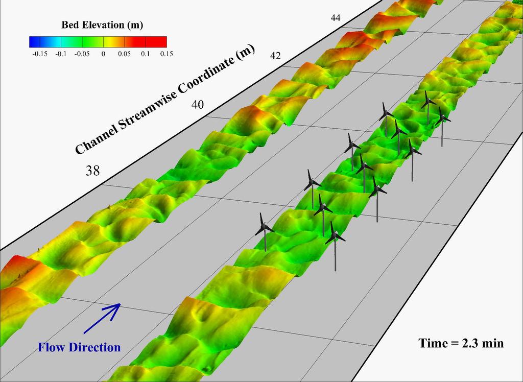
27 MHK river turbines: effects of complex turbine siting One centered turbine Bedforms remain fairly 2D with turbines centered in the channel. Two asymmetric turbines Asymmetric placement of turbines alter the channel morphology producing highly 3D patterns far away from the deployment Question: can we use MHK turbines / passive /active actuation to re-naturalize rivers while producing energy? that would be (environmentally sustainable) 2
28 The interaction between flow and energy harvesting devices has POTENTIAL APPLICATIONS FOR CONTROL Future work and some perspective for renewable energy systems Sensing boundary conditions (approaching bedforms or wind gusts) MHK river turbines: we understand how far upstream bedform migration should be monitored, what signature the turbine leaves on the river bathymetry. Can we imagine any passive / active control strategy to 1. dampen power fluctuations 2. enhance river naturalization Traditional wind energy: We learned where to measure the wind to get the most representative velocity time-series to predict power and blade strain fluctuations (Howard et al. WE 2015) offshore wind energy under ocean waves, floating platform kinematics is two way coupled with the (variable) rotor thrust force: can we use this as a restoring moment in emergency operation?
 at different heights and instantaneous power P(t) or blade strain")


29 Traditional wind energy: Temporal Cross-correlation between velocity u(t,z) at different heights and instantaneous power P(t) or blade strain (t) LiDAR at EOLOS field peak locations(z) At z/z hub ~1.3 corresponding to z=z hub +L/4 the wind velocity is mostly correlated with power output and blade strain. This signal can be thus used as a wind input for a predictive control strategy Howard & Guala WE, 2016 Eolos WT optimal location 29


")
 incoming")
 prescribe")
30 Offshore wind energy: Enable floating wind turbines with closed loop control for pitch mitigation strategy (t) obtain Thrust(t) Mitigate pitch Ω t = K d d dt (t) incoming waves H(t) Feist et al read (t) prescribe (t) Torque(t)
 limit the cross-stream blockage of the array")
31 There are three ways to approach the morphodynamic effects of MHK turbines 1) limit the cross-stream blockage of the array Video
 embrace the distortion")

32 There are three ways to address the morphodynamic effects of MHK turbines 2) embrace the distortion effect to onset meandering motions and sustain the stream naturalization with a MHK vane configuration,


")


")


33 There are three ways to approach the morphodynamic effects of MHK turbines 3) design turbines to protect the banks from erosion (with Lian Shen, Jeff Marr SAFL) Potential deployment location of singleor multi- unit systems Provisional patent application :
34 Take-home messages : 1) MHK instream turbines impose a scour deposition pattern that has local and (in some cases) a non-local effects on mean bed elevation and bedform evolution. 2) Migrating bedforms have an effect on the instantaneous power and on wake meandering 3) At the power plant scale: power fluctuations (and likely unsteady loads) depend on the coupling between wake interactions and bed evolution Mitigation strategies are possible: involve both flow preview and turbine control. For tidal or river (MHK) turbines, the key environmental impact is the morphodynamic equilibrium of the sediment bed (affect bedform-induced roughness, near-bed velocity, wall shear stress, fish life cycle, biota) changes in bathymetry are easily measurable and can be monitored for decades. It is the most robust metric we can envision to assess environmental impact C Hill, M Musa, M Guala Interaction between instream axial flow hydrokinetic turbines and unidirectional flow bedforms Renewable Energy 86, (2016) C Hill, Kozarek J. Sotiropoulos F, M Guala Interaction between instream axial flow hydrokinetic turbines and uni-directional flow bedforms WRR in press (2016) KB Howard, M Guala Upwind preview to a horizontal axis wind turbine: a wind tunnel and field scale study Wind Energy in press (2016) KB Howard, JS Hu, LP Chamorro, M Guala Characterizing the response of a wind turbine model under complex inflow conditions Wind Energy 18 ( 4), , (2015) C Hill, M Musa, LP Chamorro, C Ellis, M Guala Local Scour around a Model Hydrokinetic Turbine in an erodible Channel ASCE Journal of Hydraulic Engineering 140 (8), , (2014) C. Feist, T. Calderer, K. Ruehl, F. Sotiropoulos and M. Guala Platform kinematics and wake evolution of a floating wind turbine submitted Journal of Fluid Mech. J. Hong, M Toloui, Chamorro, Guala KB.Howard J Tucker and F Sotiropoulos Nature COMM (2014) M Guala, A Singh, N BadHeartBull E Foufoula-Georgiou Spectral description of migrating bedform and sediment transport J. Geophys. Res. (2014) A Singh, KB Howard M Guala On the homogeneization of turbulence in a turbine wake flow Physics of fluids, 2015

35 Future research we are developing a turbine scour (y s ) model, as a function of sediment (d) and rotor (D) diameter, incoming flow Froude number (F), river depth (y) and turbine operating conditions (thrust coefficient C T, induction factor or power coefficient. (Inspired by Gioia & Bombaredelli 2002, Chakrabothy & Gioia 2004, Manes & Brocchini, 2015) grain scale dynamics τ ρ = u w ~ u d V how did we get there? scour scale dynamics where y s is the scour depth and F d is the drag force y s, V

 ; with F d = ½ c T A U 2 hub at the sediment interface instead.")
36 How do we couple those scales? through turbulence kinetic energy dissipation, assuming steady conditions, K41 small scale isotropy, and the establishment of the inertial range y s, V obtain V = f( F d U hub C T...) ; with F d = ½ c T A U 2 hub at the sediment interface instead... accounting for the specific turbine scour assuming that the key length scale is the scour depth and the velocity scale in the scour hole is defined by the turbine drag
37 ~ oops! not equal, but proportional to... some exp. calibration is necessary

 a new")

38 Thank you, question? Anne Wilkinson acknowledge the other member of the team Microcystis growth and metabolism in lake-equivalent turbulence, light and temperature conditions (with Miki Hondzo) Michael Heisel wake meandering at the EOLOS turbine & (hopefully, depending on IONE funding) a new design of river flow energy converters: OCT gave us green light and support for a provisional patent... the engineering staff at SAFL (Chris, Jim 2, Jeff, Ben ) made all this possible during the renovation... the faculty: Efi, Fotis, Miki, and many others


39 Baseline flow: Verdant power large scale deployment Chawdhary et al. 2015
")
40 Asymmetric turbine patch (array) investigation

 Two turbines in series 3) Sinusoidal hill")

41 Experimental Set-up: Wind Tunnel Testing Case study utilizing PIV and voltage output Varying Thermal stratifications: 1) Turbine in baseflow 2) Two turbines in series 3) Sinusoidal hill upwind of turbine Flow Karman vortex shedding DC motor voltage Simultaneous PIV measurement windows
42 RESULTS: Turbine and Turbine interactions T ~6-10 consistent with VLSM ρ xy (τ) = v x(t)v y (t + τ) v x 2 v y 2 λ = τu convection
43 Adding complexity: Varying thermal stability regimes neutral convective stable (Howard K.B., Chamorro L.P., Guala M. AIAA 2012, to be submitted to BLM) Top tip stable neutral convective Bottom tip o Neutral - Stable - Convective


44 RESULTS: thermal stability regimes coupled with topographic effects Convective Stable U/U hub baseflow-neutral hill - stable see also Singh, Howard, Guala PoF 2014
45 Far downstream effect of centered MHK turbine(s) on bedforms Spectral analysis of bedform topography indicates little difference on reachscale sediment transport characteristics and bedform size with or without turbines;