An Innovative Approach to Improved Pulverized Coal Delivery and Combustion Optimization
|
|
|
- Cecil Davidson
- 5 years ago
- Views:
Transcription
1 SAS GLOBAL POWER TM!"#!$%&'&$()*+$*%,!-*./,%&))+$0*1*%,'23)(+,$ An Innovative Approach to Improved Pulverized Coal Delivery and Xcel Energy -Tolk Station Presented by: Michael Pelzer SAS Global Corporation SASTECH Power Consultants 2/5 Gupta Market, Lajpat Nagar-IV, New Delhi INDIA Phone: +(91) to 94 Fax: +(91) SAS Global Corporation Mullin Ave., Warren, MI USA Phone: Fax:
2 What Was Done: The mechanical and control changes made to Tolk Units 1 & 2 have allowed them to meet emission targets and defer installation of Low NO X Burners. Grind the coal correctly Distribute the pulverized coal uniformly Test, check and compare the results Control and optimize the combustion process continually Coal Flow Measurement and Balancing
3 Result: A $10 Million project was deferred six to nine years.
4 How It Was Done: Mill Upgrades Utilization of SAS Diffusion Technology Non-invasive burner modifications Diagnostic testing Coal flow distribution and balance control Implementing and monitoring innovative recommendations
5 Mill Upgrades: Were completed to extend service life of components A Multi-Outlet Diffuser was included to redistribute air/fuel mixture in turret
6 Non-uniform Pulverizer Coal Flow Causes: Poor combustion (excessive coal consumption) Higher emissions Furnace and backpass imbalances Slagging and fouling Increased opacity Reduced availability Elevated Heat Rate
7 After the Pulverizers are Optimized Adjustable Orifices are necessary for on-line fuel flow adjustments In-Line Diffusers are added to the burner configuration to atomize air fuel injection to furnace

8 SAS Global Adjustable V-Style Orifice (patent pending)

9 SAS Patented In-Line Diffusers Installed
10 Factors That Influence Combustion Fuel Flow Deviations (Pipe-Pipe, Elevation-Elevation and Corner-Corner) Airflow Deviations (Same as for Fuel) Fuel Variability Equipment Design Parameters (Boiler, Mills, Etc.)
11 Testing SAS Global Group performed diagnostic testing for fourteen days Testing done at full load, static conditions Utilized back pass emissions grid to evaluate combustion process improvement results

12 Testing Utilized both RotoProbe TM extractive and mobile microwave mass flow testing to evaluate coal flow balance. Actual sample weight recovery must be compared with expected values to validate measurement accuracy Portable Coal Flow Measurement System ACFM Machine
13 Balance Data: Example of measured fuel balance of the boiler
14 Combustion Uniformity Measurements Location: Economizer Exit/Air Heater Inlet, Pulverizer Piping, PA Inlet Ducts Equipment: Combustion Analyzers and Flyash LOI Machine, MIC, RotorProbe, ACFM
15 Example Data Plot for a Back Pass Data: Goal was to dissolve the heavy concentrations
16 SAS Global recommended the following control system settings for combustion and emissions optimization
17 Implementing Test Results Burner Tilts to Horizontal Tilt high limit ramps from 100% (15 degrees up) to 50% (horizontal) as load increases from 440 MW to 540 MW Drives tilt to horizontal as load increases, and will drive lower if temperature dictates Vary the time between IR blowers (wall blowers) to drive tilts toward horizontal
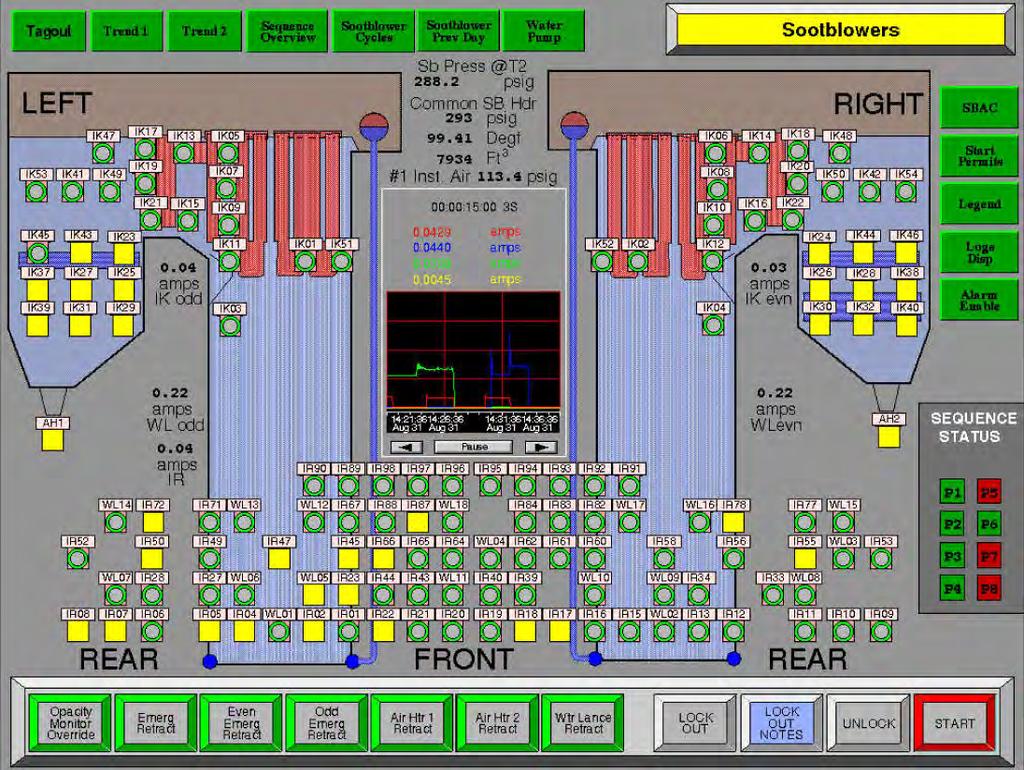
18 Sootblower Arrangement

19 Furnace Temperature Tilts are at 50% - Horizontal Location IR Sootblower at operational setting

20 Tilt Controller Tilts need to stay horizontal for good emissions Tilts tilt up at a lower load Tilts that move up increase emissions
21 Implementing Test Results AA and A auxiliary air control Dampers are controlled by Overfire Air Damper Control when A mill is off OFA Control uses characterizer blocks to add aux. air as follows: Over fire dampers AA auxiliary dampers A fuel air dampers
22 Implementing Test Results Individual Aux. Air Damper Bias Utilized existing bias blocks to increase damper position more rapidly on the individual dampers which benefit emissions

23 Backpass Testing

24 Aux. Air Dampers AAD use to operate by corner groups Now move to individually optimized combustion and emissions

25 What operators can see on screen Improve O 2 split on furnace
26 Continuous coal flow monitoring and control Coal flow balance monitoring and control Installed microwave coal flow measurement instrumentation to measure corner to corner coal flow Fixed orifices were removed and manually adjustable orifices installed Based off measurements provided by the microwave system coal flow is balanced as necessary

27 Tolk Unit 1 Weekly Average: NO X and unit load trends before and after fuel delivery system improvements NOX Levels before improvements NOX Levels after improvements
28 Results Pulverized coal delivery system optimization has resulted in: At least a 30% reduction in emissions Combustion improvements also resulted in reduced coal deliveries to Tolk Station This results in 22,000 tons less CO 2 emissions
29 Real World Change in operational priority Emissions on equal footing with Efficiency Cultures take time to change Some operators are reluctant to give control over to automated systems SAS GLOBAL POWER TM!"#!$%&'&$()*+$*%,!-*./,%&))+$0*1*%,'23)(+,$
30 SAS GLOBAL POWER TM!"#!$%&'&$()*+$*%,!-*./,%&))+$0*1*%,'23)(+,$ Other SAS Global Patented Products and Services to Optimize Combustion and Performance SASTECH Power Consultants 2/5 Gupta Market, Lajpat Nagar-IV, New Delhi INDIA Phone: +(91) to 94 Fax: +(91) SAS Global Corporation Mullin Ave., Warren, MI USA Phone: Fax:


31 SAS Global Patented (2) Piece Burner Nozzle Never have another nozzle fail from sigma phase or thermal distortion again.


32 SAS Global Patented (2) Piece Burner Nozzle Problems with other (2) Piece Nozzles Burner Nozzles fail by either thermal deterioration or by coal particle erosion. SAS Global's patented two piece coal nozzle is designed to overcome both of these modes of failure. Don't be fooled by other two piece designs. Other two piece designs split the outer housing into two pieces while still attaching the tip to the inner housing and splitter plates. The problem with this is two fold. First the inner and outer housings are exposed to different temperatures that cause the two to distort and in some cases rip apart. The second is when you remove the clips holding the outer sections of the housing together and can fall off (safety issue) and it is difficult to align a new replacement tip. Damaged by Thermal Distortion Damaged by Sigma Phase

33 SAS Global Patented (2) Piece Burner Nozzle Complete Turnkey Burner Nozzle and Barrel Assembly
34 SAS Global Patented (2) Piece Burner Nozzle Case History All 40 of the BR5 burner nozzles were replaced during the 1999 turnaround. Two nozzles from SAS Global were installed for evaluation purposes in corners 4 and 5 on A mill. The SAS nozzles differ in two aspects of their design. Firstly the leading edge of the splitter plates is overlaid with chromium carbide, which greatly extends the life of the component in this erosive service. Secondly the nozzle tip is designed to be free floating within the outer shroud. This overcomes distortion issues caused by differential expansion between the inner and outer parts of the nozzle. The following photographs illustrate how well these upgraded burner nozzles have performed relative to the OEM nozzles after 3 years.

")
35 SAS Global Patented (2) Piece Burner Nozzle Case History Figures 1 & 2 This shows the SAS nozzle installed in 5A from the furnace side. Note that the chromium carbide leading edges of the splitter plates is still intact and that the nozzle is free from distortion. (SAS)


36 SAS Global Patented (2) Piece Burner Nozzle Case History Figures 6 & 7 These show the extensive wear and deformation that has occurred with the OEM nozzles on 5B.

37 SAS Global Patented (2) Piece Burner Nozzle Case History Figure 8 This shows the extensive wear and deformation that has occurred with the OEM nozzles on 5C.
38 SAS Global Patented (2) Piece Burner Nozzle Case History Figure 9 This is a close up of the cracking issue with the OEM nozzle.

39 SAS Global Patented (2) Piece Burner Nozzle Case History Figure 10 This is another view of 5B taken from inside the pipe. OEM
40 ACFM: Advanced Coal Flow Measurement Special Features
41 ACFM: Advanced Coal Flow Measurement

42 !"#$%&'('%")**+,(-).%/0'12*+3% "/% %$-**%:-(;%<%4-2+6 ACFM: Advanced Coal Flow Measurement
)+$0*1*%,'23)(+,$ Portable High Temperature")
43 SAS GLOBAL POWER TM!"#!$%&'&$()*+$*%,!-*./,%&))+$0*1*%,'23)(+,$ Portable High Temperature Boiler Camera System
44 High Temperature Boiler Camera Services There are many common problems that are easily identified by reviewing the real time burner footage. These problems include; Flame instability/detachment Eyebrows High-unburned carbon (LOI Slagging Fuel impingement on boiler walls CO and O2 imbalance Problems adjusting secondary air and low NOx burners


45 High Temperature Boiler Camera Basic System High Temperature Camera Case Contents Video Case Contents C H

46 High Temperature Boiler Camera Services Example Flames with Highlighted Trouble Spots Ignition at Burner Face Early Ignition

47 High Temperature Boiler Camera Services Example Flames with Highlighted Trouble Spots heavy fuel concentration

48 High Temperature Boiler Camera Services Example Flames with Highlighted Trouble Spots large particle of ash

49 High Temperature Boiler Camera Services Example Flames with Highlighted Trouble Spots Slag build-up on Tubes Slag build-up on Nose