Evaluation Test Procedures for Distribution Crossarms. Southeastern Electric Exchange November, 2018
|
|
|
- Bridget Booker
- 5 years ago
- Views:
Transcription

1 Evaluation Test Procedures for Distribution Crossarms Southeastern Electric Exchange November, 2018

2 What: Research, Testing and Applications Center in the School of Electrical & Computer Engineering at Georgia Tech About NEETRAC Scope: Electric Energy Delivery (Generator to the Meter) Approach: Applied R&D, Membership Based, Consortium Focus, Self supporting Membership: Electric Utility Industry in North America Size: 37 Members, 28 Staff, $5,000,000+ History: Began in 1996 with transfer of the Georgia Power Research Center to Georgia Tech Mission: Advancing the electric grid through collaboration Facilities: High voltage, medium voltage, mechanical & environmental 2

3 Membership NEETRAC started with 10 Members in We now have Utilities 14 Manufacturers 3 Associates Utility Membership 76 million US Electric Customers ~ 60% of US Customer Base Manufacturer Membership Represent a large portion of the providers of products and services to the electric utility industry 3

4 Membership NEETRAC has regular contact with approx. 140 utilities & 31 manufacturing sites 4
5 Member Value On Call Technical Resource 350 years (approx.) in T&D arena Broad Perspective Application / Research / Testing Utility & Manufacturer NEETRAC Membership Independent Fact-Based Knowledge Based on input from Members Leveraged Collaboration Technical Knowledge 37:1 Funding 30:1 (approx.) 5
 Consultation Testing Quality assurance Asset management Plant audits Product")
6 Project Types Baseline Projects Collaborative Cost shared by all NEETRAC members Project ideas generally come from NEETRAC members Each Member assigns advisors Board meets 3 times/year Ideation Proposals Closeouts Networking/collaboration Interim results Input Industry forum Direct Placed (Proprietary) Consultation Testing Quality assurance Asset management Plant audits Product evaluation 6


7 About the Authors Caryn Riley, Ph.D. Joe Goldenburg, P.E. Ph.D. in Electrical Engineering Manages NEETRAC s Electrical Section 20 years experience Bachelors in Mechanical Engineering Manages NEETRAC s Mechanical Section 25 years experience 7
8 The White Paper Response to numerous questions from several members regarding testing crossarms and how to interpret the data. Ten NEETRAC members funded and participated in the writing and publication of this white paper. The white paper covers the following areas of Crossarm testing: Mechanical Testing Electrical Testing Environmental Testing The white paper discusses test methods that are applicable to a range of crossarm technologies (wood, steel, composite, laminate, etc.) 8
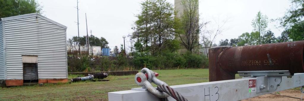
9 Mechanical Testing The primary purpose of a crossarm is to support the mechanical load of the conductors, insulators and related hardware. Mechanical loading of crossarms is specified by a variety of documents including: National Electric Safety Code (NESC) requirements Utility internal standards RUS Bulletin 1724E-151, Mechanical Loading on Wooden Distribution Crossarms Manufacturer product specification sheet IEEE Std C , IEEE Standard for Fasteners for Overhead Line Construction ANSI/IEEE C2 National Electric Safety Code (NESC),
10 Mechanical Testing Overall Length Reaction Span Test Load Bolt attachment location 10
11 Mechanical Testing F F F 11

12 Mechanical Testing F F F 12

13 Mechanical Testing 13
14 Mechanical Testing 14

15 Mechanical Testing 15
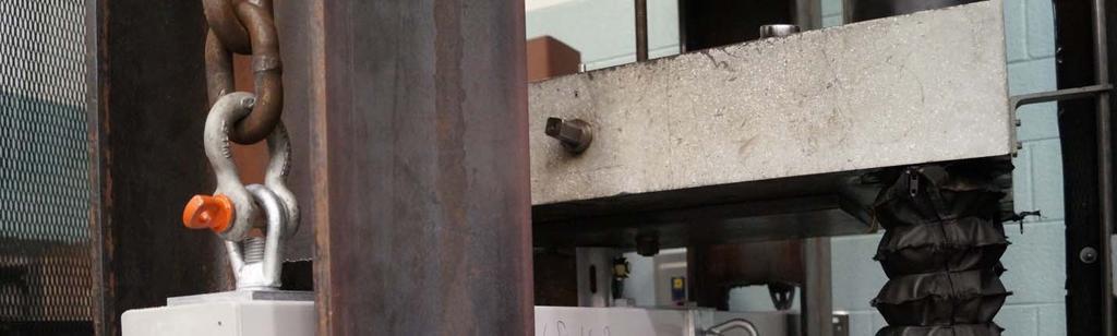
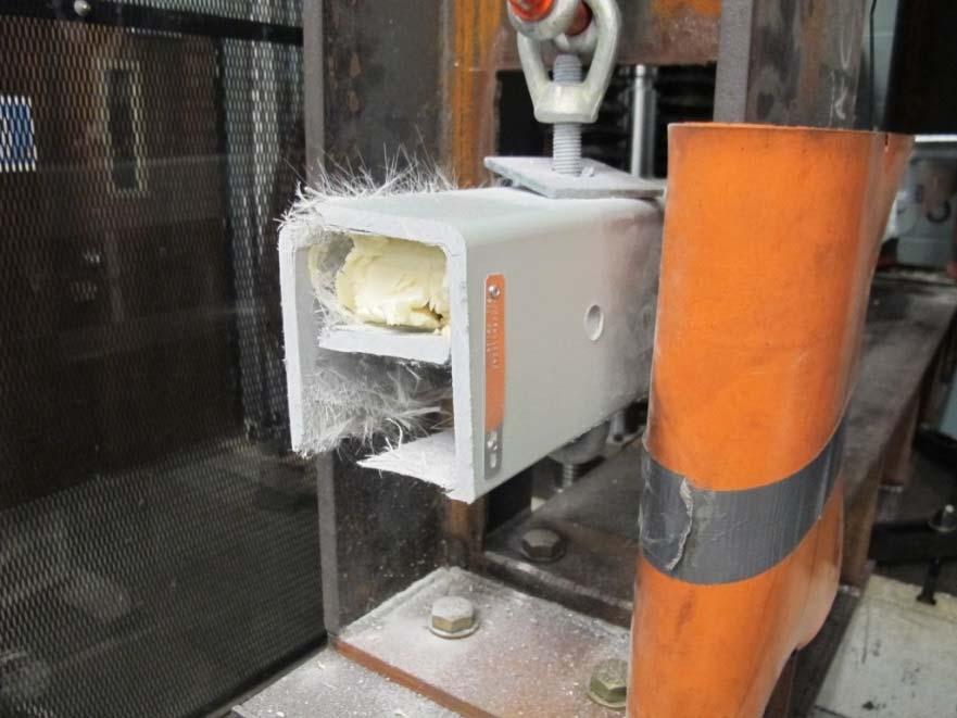
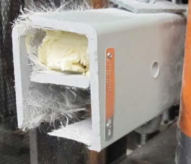
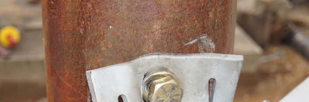
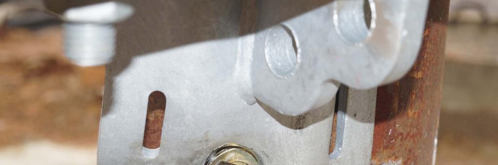
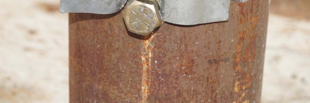
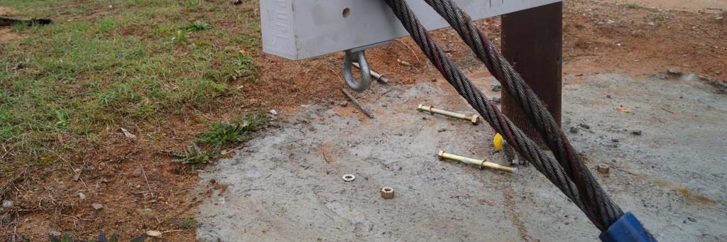
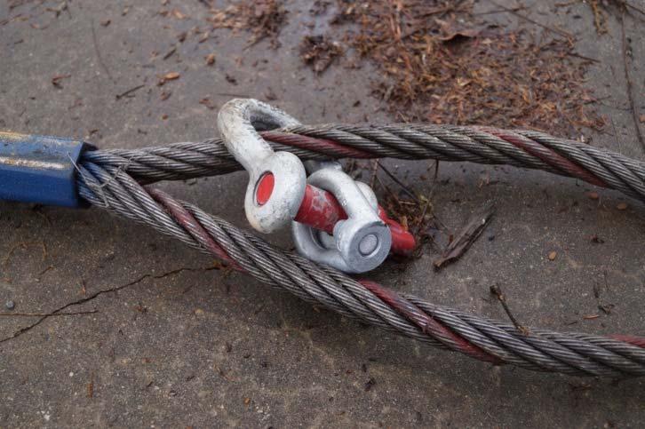
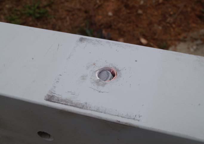
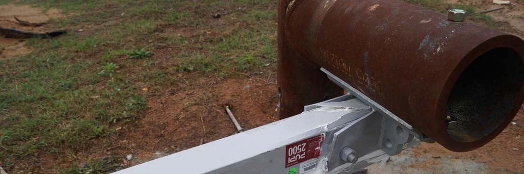
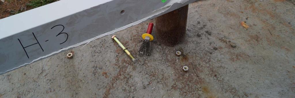
16 Mechanical Testing Test crossarms with the hardware and loading scenarios anticipated in the field. There are interactions between various components. Any part of the crossarm assembly can fail a test. including the beam, washers, bolts, eyes and gain. When possible test fully assembled crossarms! 16

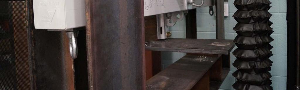
17 Mechanical Testing Imbalanced loading scenarios are common. 17

18 Mechanical Testing 18
19 Mechanical Testing 19

20 Mechanical Testing F 20

21 Mechanical Testing 21

22 Mechanical Testing 22
23 Mechanical Testing 23

24 Mechanical Testing 24
25 Mechanical Testing 25
26 Mechanical Testing F 26
27 Mechanical Testing 27
28 Mechanical Testing 28

29 Mechanical Testing 29

30 Mechanical Testing F M 2 M 1 30

31 Mechanical Testing 31

32 Mechanical Testing 32

33 Mechanical Testing (Torque) 33

34 Mechanical Testing 34

35 Mechanical Testing Some utilities and manufacturers also require tests on individual sections or plaques removed from manufactured crossarms. Tests frequently involve pre and post conditioning that could include thermal cycling, UV, or chemical exposure. Testing plaques can provide useful information for laboratories conducting research on isolated performance characteristics. Utility engineers should be cautious about extrapolating test results to real world performance of a full crossarm. 35
36 Electrical Testing Traditionally, distribution crossarms do not have electrical ratings. Non wood alternative crossarm materials such as fiberreinforced polymer (FRP) crossarms have introduced the concept of testing the electrical properties of the crossarm material itself. No North American standards dictate a pass/fail electrical rating for any type of distribution crossarm. The physical arrangement of the crossarm components are determined by the voltage rating of the line, the line design, and the required additional equipment such as fused disconnects, surge arresters, transformers, reclosers, etc. 36

37 Electrical Testing The placement of these components as well as the grounding design dictates the electric field patterns and potential leakage current paths across the crossarm. If the dielectric performance of a distribution utility crossarm is to be evaluated, a full-size crossarm setup should be used and the phase-to-phase distances as well as the grounding design must be documented. 37
38 Electrical Testing - Power-frequency Testing (1 of 2) Uses an alternating voltage with a frequency between 45 to 65 Hz. Per IEEE , the voltage waveshape should be a sinusoid with a ratio of peak-to-rms values equal to 2 within ± 5%. This testing is used to evaluate the apparatus under simulated in-service field conditions. Two different types of tests are typically used. Withstand Disruptive discharge (flashover) The exact test parameters and pass/fail conditions are left up to the apparatus standard. 38
39 Electrical Testing - Power-frequency Testing (2 of 2) As there are no standards which address the electrical ratings of crossarms, the manufacturer and user need to define their specific requirements. Users are cautioned that differences in withstand or disruptive discharge voltages between technologies or within technologies may not be indicative of better or worse performance. It may be worthwhile for users to benchmark their existing crossarm technologies and assemblies. 39
40 Electrical Testing - Impulse Testing (1 of 2) Impulse testing uses a voltage with a waveshape characterized by its front time, peak voltage and time to half-value. Two terms are commonly used to discuss impulse ratings of utility components BIL and CFO. Basic impulse withstand level or basic insulation level (BIL) is accepted by most utilities to be the crest value of a standard lightning impulse for which the insulation exhibits 90% probability of withstand or a 10% probability of failure (where failure is a disruptive discharge). The CFO voltage (critical flashover voltage) has a fixed probability of 50% and is defined as the crest value of a standard lightning impulse for which the insulation exhibits 50% probability of withstand or failure. 40
41 Electrical Testing Impulse Testing (2 of 2) Research has been conducted on the CFO levels of crossarms of different material types. These values are a function of the test setup, sample length and sample material. The majority of the published research was designed to determine a CFO level of the material for comparison. Users are encouraged to examine their specific crossarm construction designs as the final CFO level will be affected by Clearance distances between phases Placement of other apparatus This may result in the crossarm material having little to no effect on the electrical rating of the complete system. 41
42 Crossarm materials can be tested to evaluate their relative dielectric strengths. Tests are typically performed on small samples and provide an assessment of the material itself, not the full apparatus. ASTM D Standard Test Method for Dielectric Breakdown Voltage and Dielectric Strength of Solid Electrical Insulating Materials at Commercial Power Frequencies Electrical Testing - Materials Defines three test procedures to determine the dielectric strength of solid insulation materials at commercial power frequencies. This standard specifically states that the results obtained by this test method can seldom be used directly to determine the dielectric behavior of a material in an actual application. The test results are provided as a dielectric strength typically in V/unit length and are best used for process control, acceptance or research testing. 42
43 Environmental Testing - Corrosion Relevant Standards: ASTM A153/A153M-16a, Standard Specification for Zinc Coating (Hot-Dip) on Iron and Steel Hardware ASTM B117-16, Standard Practice for Operating Salt Spray (Fog) Apparatus ASTM G85-11, Standard Practice for Modified Salt Spray (Fog) Testing ASTM D610-08(2012) Standard Practice for Evaluating Degree of Rusting on Painted Steel Surfaces ASTM A1059/A1059M-08(2013), Standard Specification for Zinc Alloy Thermo-Diffusion Coatings (TDC) on Steel Fasteners, Hardware, and Other Products 43


44 Environmental Testing - Corrosion Corrosion is a reduction in a metal component crosssectional area that occurs when it interacts with oxygen. Coatings are typically used to protect metal components by creating a barrier that prevents oxygen from chemically reacting with the metal part. 44
 or mass-loss (destructive method).")
45 Environmental Testing - Corrosion ASTM A153 (Standard Specification for Zinc Coating (Hot-Dip) on Iron and Steel Hardware) is a manufacturing specification utilities often use to specify the coating on their crossarm hardware. Coating thickness can be measured using a magnetic thickness gauge (non-destructive method) or mass-loss (destructive method). 45


46 Environmental Testing - Corrosion Salt fog test methods can only be used to compare the relative performance of various coatings to the selected salt fog test protocol; no life extrapolations to real world exposure. 46
47 Environmental Testing - Corrosion Salt fog test methods ASTM B117 (Standard Practice for Operating Salt Spray (Fog) Apparatus) most frequently used. o Provides continuous salt spray o Neutral ph of 7 ASTM G85 (Standard Practice for Modified Salt Spray (Fog) Testing) is gaining acceptance. o Cycles between spraying salt solution with drying periods. o Acidic ph of 3 o Considered more real world as it uses both wet and dry cycles in the test program, especially for acid rain / industrial environments. o Annexes allow you to select different environments. 47


48 Environmental Testing - Corrosion Two different galvanizing technologies Hot dipped galvanizing o Temperature: 435 C to 455 C o Immersion time: 5-7 minutes Thermal diffusion galvanizing o Temperature: 320 C to 480 C o Time: 2-4 hours (Source: precimaxonline.com) (Source: Distek youtube) 48
49 Environmental Testing - Corrosion Thermal diffusion galvanizing (TDG) is a relatively new galvanizing technology. ASTM A1059 (Standard Specification for Zinc Alloy Thermo-Diffusion Coatings (TDC) on Steel Fasteners, Hardware, and Other Products) provides a loose framework and process controls for thermal diffusion galvanizing. Tests performed at NEETRAC found that there was significant variation in the effectiveness of the thermal diffusion galvanizing processes used by different manufacturers. ASTM D610 (Standard Practice for Evaluating Degree of Rusting on Painted Steel Surfaces) provides a useful resource that can be adapted for grading the performance zinc coated parts. 49
50 Environmental Testing Weathering (UV) (1 of 10) Q-Lab * Technical Bulletins LU-0822: Sunlight, Weathering and Light Stability Testing LU-0833: Correlation Questions and Answers A discussion of the most frequently asked questions about accelerated weathering LL-9031: QTRAC Natural Sunlight Concentrator Accelerated Natural Outdoor Exposures LU-8030: Errors Caused by Using Joules to Time Laboratory and Outdoor Exposure Tests LU-8009: QUV and Q-Sun A Comparison of Two Effective Approaches to Accelerated Weathering and Light Stability Testing LU-8035: Comparison Between Natural Weathering and Florescent Exposures *-Global provider of material durability testing products 50
51 Environmental Testing Weathering (UV) (2 of 10) ASTM International Standards ASTM G Standard Practice for Operating Fluorescent Ultraviolet (UV) Lamp Apparatus for Exposure of Nonmetallic Materials ASTM G Standard Practice for Exposing Nonmetallic Materials in Accelerated Test Devices that Use Laboratory Light Sources ASTM G Standard Practice for Operating Xenon Arc Light Apparatus for Exposure of Non- Metallic Materials ASTM G90-10 Standard Practice for Performing Accelerated Outdoor Weathering of Nonmetallic Materials Using Concentrated Natural Sunlight 51
52 Environmental Testing Weathering (UV) (3 of 10) Regardless of the accelerated weathering test protocol chosen, the results only allow you to compare the relative performance of samples tested to the spectral light distribution, temperature and humidity of the test that was performed. Caution is required when interpreting UV exposure test results. The amount of radiation incident on the sample is sometimes erroneously considered an accelerating factor to predict the life of a product. For example, if a product receives the equivalent of five years of radiation in six months, this is sometimes wrongly considered to correlate to five years of UV exposure outdoors. Equivalent radiation dosage does not lead to equivalent degradation. 52
53 Environmental Testing Weathering (UV) (4 of 10) Q-Lab Bulletin LU-8030 explains the reasoning for this warning stating, Replicate specimens receiving the same accumulated radiation dosage often show vastly different degradation. This is because timing in Joules does not take into account the substantial variations in weathering stress caused by the following other factors: Differences in Spectral Irradiance Differences in Exposure Temperature Differences in Moisture Exposure ASTM G151 states that for accelerated testing: Even though it is very tempting, calculation of an acceleration factor (ASTM italics) relating x hours of a laboratory accelerated test to y months or years of exterior exposure is not recommended. 53
")
54 Environmental Testing Weathering UV (5 of 10) 54
55 Environmental Testing Weathering UV (6 of 10) 55

56 Environmental Testing Weathering UV (7 of 10) 56


57 Environmental Testing Weathering UV (8 of 10) = 57
58 Environmental Testing Weathering (UV) (9 of 10) Another debate is natural sunlight exposure versus artificial light (fluorescent, xenon arc, etc.). Natural sunlight, especially when concentrated using mirrors, is not as repeatable as an artificial light indoor test where spectral irradiance, temperature and humidity can be better controlled. ASTM G90 states, [ASTM G90] should not be used to establish a pass/fail approval of materials after a specific period of exposure unless performance comparisons are made relative to a control material exposed simultaneously Ideally, accelerated weathering testing should be conducted on full size crossarms. Practically, few laboratories have UV chambers large enough to conduct such testing so plaques are often created from sections of crossarms and placed in test equipment. 58
59 Environmental Testing Weathering (UV) (10 of 10) Accelerated weathering testing in and of itself may not provide a good indication of crossarm performance. Need to ask: How does UV degradation affect the mechanical and dielectric strength of the crossarm?. Physical appearance may not indicate strength reduction. 59
60 Summary Mechanical testing: Strength is the #1 requirement ALL crossarms must meet. Test full size crossarms in real-world loading scenarios Electrical testing: Test full size crossarm setups with the phase spacing and potential additional hardware as installed in the field. Benchmark your current crossarm technology (both new and aged) to compare relative performance with emerging technologies. Environmental Corrosion testing on hardware is important. Accelerated UV testing allows you to compare UV performance but o Can t predict life (no accelerating factor) o May not correlate to strength loss. 60
61 Questions Questions 61