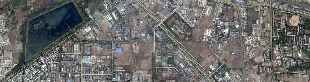
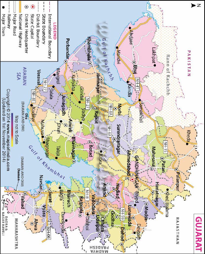
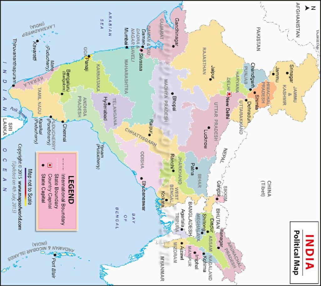
Annexure 1: Site Location Map
|
|
|
- Amos Bennett
- 5 years ago
- Views:
Transcription
1 Annexure 1: Site Location Map


2 Asian Paints Limited
3 Annexure 2: GIDC Plot Allotment Letter
4
5
6
7
8
9
10
11
12
13
14
15
16
17
18
19
20
21
22
23
24
25
26
27
28
29 Annexure 3: Site Layout Map


30 N W E Project Site Phthalic Plant Paint Plant S A B No Latitude A 21 37'32.47"N Longitude 73 1'25.02"E B C 21 37'31.56"N 21 37'24.05"N 73 1'40.18"E 73 1'39.72"E D 21 37'23.78"N 73 1'36.78"E H G D C E 21 37'16.92"N 73 1'36.31"E F 21 37'17.40"N 73 1'25.82"E G 21 37'24.17"N 73 1'26.20"E H 21 37'24.44"N 73 1'24.37"E F E SCALE M
31 Annexure 4: Details of Demolition
32 Waste generated during Construction and Demolition activities at Phthalic Plot The following wastes are expected to be generated during Construction and Demolition activities at Phthalic Plot. 1) Hazardous waste 750 MT 2) Structural Steel: 1137MT 3) Civil debris 10685MT The figures are estimated figures. However, these can very post actual dismantling and demolition. The Hazardous waste generated will be disposed in safe and environment friendly manner as per the guidelines laid down by Central Pollution Control Board (CPCB) and Gujarat Pollution Control Board (GPCB). All possible reusable demolition waste will be reused during the construction process. However, for the Construction and Demolition waste that cannot be reused, we will dispose the same in a suitable and environment friendly manner as per the directions of the Pollution Control Board.
33 Annexure 5: Production and Manufacturing Process
34 Details of Manufacturing Process M/s Asian Paints Limited proposes to manufacture Enamels, Water based Paints, Varnishes, Thinners, Stainers, Synthetic Resins and Emulsions at its Ankleshwar division. 1.1 Manufacturing of water based paints, enamels, varnishes and thinners The enamels, water based paints, varnishes and thinners manufacturing by mixing process involves the following steps: 1. Wetting the pigment with sufficient quantity of appropriate resin / water in presence of surfactant. This process called pre-dispersion or premixing is achieved in Cowl's dissolver or similar pre-disperser. 2. The next step involves further breaking up of the pigment aggregates and their suspension in resins. Sand mills are used for dispersion. Type of paint and nature of pigment dictate the selection of a mill or a combination of mills. Ball mills can also be used as dispersion equipment. In such a case pre-dispersion is not necessary. All the ingredients are directly charged into the mill and the mill is run for the specified time to achieve requisite characteristics. 3. Adjusting the shade consistency and other desired properties of the product is the next step. The milled pigments are transferred to mixers where additives like drying agents are added. The remaining quantity of materials likes resins/emulsion and thinners are also added in mixers. The consistency, viscosity, colour and drying time & other parameters are adjusted in the mixer. 4. The final step is packing of the paints in containers. On approval of the paint against specifications, the paint is strained and packed in required pack sizes. The pack size and type of paint decide the appropriate packing machine. In case of both the types, Faster Packing Machine is also being utilised, which provides more accuracy on filling. The process of enamel production using ball mills and process of enamel, water based paints, varnishes and thinners production using sand mills are depicted in Fig and Fig respectively. The process schematic of water based paint is shown in Fig
35 Fig : Flow Diagram for Enamels by mixing process
36 Fig : Flow Diagram for Enamels, Water Based Paints, Varnishes and Thinners by mixing process
37 Fig : Flow Diagram for Water Based Paint by mixing process
38 1.2 Manufacturing of Paints using Pug Mixers Water based stiff paints are wall finishes, sold in the form of stiff pastes of uniform and smooth consistency. Processing of water based stiff paints is carried out in a single stage in pug mixers that have a pair of helical mixers revolving in opposite direction. The powdered raw materials charged through PLC operated pneumatic conveying system to separate hoppers available on each pug mixer. This system is helping in reduction in Dusting and material loss. Binder solution and other additives are charged in pug mixer. The dispersion is achieved by the sheer force and pugging action generated in the pug mixer. Shade and other adjustments are carried out in the pug mixer itself and the material is packed on special packing machines suitable for stiff mass. The process of manufacture is depicted in Fig Fig : Flow Chart for Water Based Stiff Paints by mixing only
39 1.3 Manufacturing of resins a. Alkyd resins Synthetic resins of alkyd type are manufactured by chemical reactions of polyol, oil and polyacid in presence of catalyst and certain additives in thermic fluid heated reaction vessel. The reaction is monitored by checking temperature, viscosity, acid value and percent solids. Time required for reaction varies from 18 hrs to 48 hrs. This is followed by thinning in blender with solvents to the desired percentage solids and filtration take place in a plate type pressure filter and after filtration the product is pumped into storage tanks. The above mentioned process is shown in Fig Fig : Flow Chart for Alkyd Resin Processing b. Emulsion resins: Following steps are involved in manufacturing process 1. Water and surfactants are taken to the reactor and heated to O C. On achieving desire temperature, initiator catalyst is added. The temperature of the contents is controlled to C 2. Monomers are added continuously to the reactor under continuous stirring. 3. On completion of monomer addition, catalyst is added to the reactor. The reactor is maintained at around 80 O C for two hours to ensure complete polymerisation.
40 4. On cooling, the emulsion is neutralised and other additives like defoamer and preservatives are added. 5. The emulsion is strained and stored. The process flow sheet is shown in Fig Fig : Flow Chart for Emulsion Processing Unit c. Amino Resins Solvent and other required additives are charged in the reactor. Remaining part is taken to premix tank. The reactor is heated to 75-80OC in atmosphere of nitrogen under continuous stirring. The catalyst is mixed with the solvents and added to the reactor at 70-80OC for min. Temperature increase is recorded and desired temperature is maintained by cooling. The contents of premix tank are added slowly and continuously to the reactor. On completion of addition of premix solution, the catalyst is added to the reactor. The reactor is maintained at 80OC to 120 OC for 4-6 hours to ensure complete polymerisation. Water of reaction is collected in a separator. After achieving desired in-process parameter, it is cooled to C. Recovered solvent of previous batch is added to thin down the resin. Desired parameters are again checked and adjusted. Post approval, product is packed in barrels.
41 Manufacturing of Stainer/AMC 1. Wetting the pigment with sufficient quantity of appropriate surfactant and water, thereby breaking large agglomeration to make a mill base which has a correct consistency for grinding. This process called pre-dispersion is achieved in Cowl's dissolver or similar predisperser. 2. The next step involves further breaking up of the pigment aggregates. Highly efficient grinding equipment, i.e. ECM Poly is used for dispersion. All the ingredients are directly charged into the mill and the mill is run for the specified time to achieve requisite characteristics. 3. Adjusting desired properties of the product is the next step. The milled pigments are transferred to mixers where additives are added. The remaining quantity of materials like water is also added in mixers. The consistency, viscosity, colour and other Physical parameters are adjusted in the mixer. 4. The final step is packing of the product in containers. On approval of the product against specifications, it is strained and packed in required pack sizes. The pack size decides the appropriate packing machine. The process of Stainer production is depicted in Fig Fig : Flow Chart for Stainer/AMC Processing Unit
42 Process for Captive Power Generation Plant: Steam Cooling Tower Water Inlet WHRB 430kg/hr 90 0 C 80 0 C Engine 678 Kw Stack Soft Water Engine driven pump Chilled Water Outlet LiBr Chiller 95 TR Booster Pumps P H 44 m 3 /hr Chilled Water 168m 3 /h 90 0 C 80 0 C Cooling Water Pumps 32 0 C Radiator The plant has installed 2 Nos of 678 kwh capacity natural gas based Captive Power Plant as a part of COGENERATION Project at an investment of Rs.2.3 Crores. The salient features of this system are: Waste heat released in the form of exhaust gas and hot water is used in following manner for maximum energy utilization: High temperature exhaust gas of the Gas Engine is fed to a Waste Heat Recovery Boiler (WHRB) for generation of high pressure steam. This steam is used for process heating purpose. High temperature water ex-hot engine jacket is used in a Lithium Bromide Vapour Absorption Chiller for generating chilled water. This chilled water is used in process for cooling purpose. Thus it helps in reducing cost as well as reduction in consumption of natural resources.
43 Starting Procedure: 1. Start Chilled water pump. 2. Start Hot water pump. Ensure rated flow =44 M3/Hr. 3. Go to operation screen on VAHP 4. Start VAHP in operation screen by pressing the START key. (F1 Key) 5. Ensure Absorber pump starts. 6. Ensure cooling water pump starts & check rated pressure drop of 0.8kg/cm2. 7. Ensure hot water three way control valve opens slowly. 8. Ensure Refrigerant pump starts. 9. Ensure cooling tower fan starts if temperature goes above set point (280 C). Stopping Procedure: 1. Go to operation screen on VAHP 2. Stop VAHP by pressing STOP key. (F2 Key) 3. Ensure hot water control valve closes immediately. 4. Ensure Refrigerant pump stops immediately. 5. Ensure cooling water pump stops one minute after stopping the machine. 6. Ensure Absorber pump runs for 15Min in DILUTION cycle. 7. Stop Hot water pump. 8. Stop chilled water pump after completion of dilution cycle.
44 Annexure 6: Storage Details of Raw Material
45 Annexure 6: Raw Material Storage Details Operating S. No. Chemical State Hazard Involved Means of Storage (Tentative) Storage capacity No. of storage means Condition Press Temp, Kg C /Cm 2 1 Additives Liquid Low flammability SS Tanks 2 Extenders Powder - CS/SS Silos 3 Monomers Liquids 4 Pigment Liquid/ Solids 5 Solvents Liquid Low flammability Low flammability High flammability CS/SS Tanks Silos/ Jumbo Bags (Re-usable) CS Tanks To be given at time of EIA 6 Oils Liquid 7 Resin RMs Powder Low flammability Low flammability CS Tanks /Jumbo Bags (Re-usable)
46 Annexure 7: Preliminary stage of Proposed ETP
47 Annexure 7: Details of Effluent Treatment Plant Primary Treatment Secondary Treatment Tertiary Treatment Industrial Effluent Gardening Domestic Effluent Permeate for Re-use Reverse Osmosis (RO) Condensate for Re-use Multiple Effect Evaporator (MEE) Solid waste for landfill / incineration/ co-processing The trade effluent streams shall be collected in individual collection tanks at the respective blocks. The transfer of trade effluent to the ETP will be based on operator-controlled flow using a metering pump through overhead pipelines. Operator would change the metering rate based on tank level or influent flow. Domestic sewage is collected in Sewage Collection Pit near the generation source and by pumping through overhead pipelines is directly added to bio-reactor Tank of ETP. The ETP consists of 3-stage treatment phases i.e. Primary Treatment, Secondary Treatment and Tertiary Treatment. Trade Effluent undergoes all three phases of treatment. Sewage will undergo combined treatment with Primary-treated Trade-Effluent in the Secondary-treatment-phase and Tertiary-treatment-phase. The trade effluent will be led to primary (physico-chemical) treatment system. The primary treatment system shall comprise multiple Primary Treatment Tanks. Each tank will have stirrer and common Chemical Dosing Facility. There will be oil and grease removal unit prior to Primary Treatment Tanks. The Primary Treatment Tanks will operate in Fill-Dose-Draw mode. At any given time, one tank will receive the untreated trade effluent while the other will be subjected to chemical dosing and transfer for secondary (biological) treatment. The Primary Treatment Tank, wherein the required chemicals have been dosed, shall be left for minutes for settling. On settling, the supernatant shall be drained to Bio-reactor and then, the sludge shall be drained to Sludge
48 Holding Tank. Decanter Centrifuge will be used for dewatering of sludge. The dewatered and dried sludge will be declared as Hazardous Waste under the Category 34.3 of Hazardous Waste (Management, Handling and Transboundary Movement) Rules 2009, and be disposed by Incineration/Co-processing or Secured Landfill at TSDF. Domestic sewage shall flow directly to Bio-reactor Tank. The primary treated trade effluent shall be pumped at uniform flow to the Bio-reactor Tank. Dissolved Oxygen level in aeration tank will be measured once every shift. The bio-treated effluent shall be collected in a Tertiary-Treatment Feed-Sump. Hypo-chloride solution shall be dosed using metering pump. The effluent shall be pumped through Pressure Sand Filter and Activated Carbon Filter for polishing treatment. Excess bio-sludge from bio-treatment shall be drained to Sludge Holding Tank. The sludge in the Sludge Holding Tank shall be pumped to Decanter Centrifuge for dewatering. The treated effluent shall be passed through Reverse Osmosis plant (RO). The RO permeate will be used as fresh water back into manufacturing processes or utility or gardening. Whereas, RO reject will be disposed using multipleeffect evaporator (MEE).
49 Annexure 8: Details of Hazardous Waste
50 S. No. 1 2 Waste Description Oil contaminated with waste water & sludge Sludge and filters contaminated with oil Category Sources of Generation Paint plant Phthalic Plant HW Generation Total Existing Net Increase / Decrease After Amalgamation and Expansion of Paint Plant 3.1 All Tanks (other than water) bottom sludge Used / Spent Oil Discarded Asbestos sheet Contaminated aromatic, aliphatic or naphthenic solvents, may or may not be fit for reuse Distillation Residues Process Waste (Landfill +Incinerable) 15.2 Soil contaminated with any material (RM / Intermediate / Product) Vermiculite / adsorbent contaminated with any material (RM / Intermediate / Product) Engineering Consumables (such as oilfilters) contaminated with any material Used / overflow Thermopack oil Spent lubricating oil /grease Used oil such as hydraulic testing oil, transformer oil Discarded Asbestos Sheets, Discarded Asbestos Panels, Used Asbestos Gaskets /cuttings 20.1 Waste solvent 20.3 Distillation Residue 21.1 Waste powder Test samples of RM, Non - Resin Intermediates and FGs Gelled paint / paint with excess bacterial growth / paint lumps) Scrappings of dried paint Spilled RM, Non - Resin Intermediates and FGs Paper / paper cups / PPEs contaminated with RM / Intermediate / FG UoM MT/Ann um MT/Ann um MT/Ann um KL/Ann um MT/Ann um Disposal Method Incineration- In house or at TSDF/ Coprocessing Incineration- In house or at TSDF/ Coprocessing Sale to authorized recycler Disposal at TSDF secured landfill Sale to authorized recyclers/ Incineration- In house or at TSDF/ Coprocessing Incineration- In house or at TSDF/ Coprocessing Sale to authorized recycler/ Incineration- In house or at TSDF/ Co-processing
51 SS / Heliflex / PVC / CI /Cement / HDPE / Rubber pipe contaminated with RM / Intermediate / FG Discarded Resin / emulsion / polymer Resin /emulsion / polymer test samples Wastes / residues Wastes / residues such as filter aids Chemical containing residue arising from decontamination Discarded containers / barrels /liners contaminated with hazardous wastes / chemicals (Liners)-Landfill Discarded containers / barrels /liners contaminated with hazardous wastes / chemicals (Liners)- incinerable Discarded containers / barrels /liners contaminated with hazardous wastes / chemicals (Packing material and sample containers) Scrappings of Resin /emulsion / polymer Gelled particles / flakes of resin / emulsion /polymer By product salts contaminated n with resin Spilled resin/ emulsion/ polymer material Oil-contaminated and water contaminated Resin from Dust Collector. Used dicamol, Arbocel, celite, cuno / GAF filter, Filter Bags, Waste filter cloth, Sieve, Mesh Leftover material from RM container (Barrel / Carbouy / Drum / Tote) All containers for RM, Intermediates, Consumables (Plastic) All containers for RM, Intermediates, Consumables (Paper) All contaminated metal Packing Material containers including sample tins All contaminated plastic Packing Material containers MT/Ann um MT/Ann um MT/Ann um MT/Ann um MT/Ann um Number s/annu m Incineration- In house or at TSDF/ Coprocessing/ Sale to authorized recycler Incineration- In house or at TSDF/ Coprocessing Incineration- In house or at TSDF/ Coprocessing Secured Landfill at TSDF Incineration- In house or at TSDF/ Coprocessing/ Secured Landfill at TSDF/ Sale to authorized recycler Incineration- In house or at TSDF/ Coprocessing/ Secured Landfill at TSDF/ Sale to authorized recyclers
52 Discarded containers / barrels /liners contaminated with hazardous wastes / chemicals (Barrels / Carboys / Drums / Totes/IBC s) Flue gas cleaning residue Spent Ion Exchange Resin containing toxic metals Chemical sludge from waste-water treatment (dry basis) Oil and Grease skimming residue Ash from incineration of hazardous waste Lead Acid Batteries 33.1 Contaminated Liners and bags (plastic / paper), except those of extenders Soot / carbon black Resin beads Gutter / drain sludge Effluent collection pit sludge Equalization tank / guard pond sludge Primary Treatment tank / Thickener Sludge Centrifuged sludge Chemical sludge from SDB Chemical salts from MEE Floating oil / solvent on trade effluent / sewage Inorganic ash Schedule III, Part A1, A Spent Carbon 36.2 Used /Waste lead acid batteries Used /Waste lead acid batteries (Excisable) Used carbon granules from common scrubbers Number s/annu m MT/Ann um MT/Ann um MT/Ann um MT/Ann um MT/Ann um Number s/annu m MT/Ann um Sale to Authorized vendors Incineration- In house or at TSDF/ Coprocessing/ Secured Landfill at TSDF Incineration- In house or at TSDF/ Coprocessing/ Secured Landfill at TSDF Incineration- In house or at TSDF/ Coprocessing Incineration- In house or at TSDF/ Coprocessing Co-processing/ Secured Landfill at TSDF Sale back to supplier/authorized recycler Return to supplier for regeneration/ Incineration- In house / Co-processing
53 23 25 Sludge from treatment of waste water arising out of cleaning / disposal of barrels / containers (Dry Basis) Contaminate potassium nitrate and sodium nitrate C12/C Spent catalyst Wastes cotton containing Waste gaskets Filter and filter material ETP waste MT/Ann um MT/Ann um MT/Ann um MT/Ann um MT/Ann um MT/Ann um MT/Ann um Incineration- In house or at TSDF/ Coprocessing Collection, storage transportation & Disposal at TSDF BEIl Collection, storage transportation & Disposal at TSDF BEIl Ankleswar Collection, storage transportation & Disposal at TSDF BEIl Ankleswar Collection, storage transportation & Disposal at TSDF BEIl Ankleswar Collection, storage transportation & Disposal at TSDF BEIl Collection, storage transportation & Disposal at TSDF BEIl Ankleswar
54 Annexure 9: Application made for additional increase of water and Power
55
56 Annexure 10: Water Consumption Details
57 Total water consumption will be 1000 KLD as per shown in Table 1, which will be provided by GIDC (Gujarat Industrial Development Corporation). Effluent generation is mainly from cleaning of process equipment s and from domestic usage. Table 1: Water Consumption Details S. No. 1 2 Area of Consumption Industrial Consumption Domestic Consumption Capacity (KL/day) - Paints Capacity (KL/day) - Phthalic Gardening Combine d capacity (Existing ) -KL/day Additional Requiremen t KL/Day Proposed capacity (Existing ) - KL/day Total Table 2: Waste Water Generation Details S. No. Area of Generation - Wastewater Capacity (KL/day)- Paints Capacity (KL/day)- Phthalic Combined capacity (Existing) - KL/day Additional Generation KL/Day Propose d capacity -KL/day 1 Industrial Domestic Total
58 Annexure 11: Fuel Consumption and stack Details
59 Annexure 11: Fuel Consumption and Stacks S no Name of the Fuel Existing Capacity at Paints plot Existing Capacity at Phthalic plot Combined Capacity (Existing) Proposed Capacity 1 Natural Gas (NG) 775 m3/hr. 391 m3/hr m3/hr m3/hr. 2 High Speed Diesel (HSD) 120 lit/hr. 660 lit/hr. 880 lit/hr. 880 lit/hr. 3 Furnace Oil (FO) 544 Kg/hr Kg/hr. 544 Kg/hr. S. No. Stack Attached to Capacity Stack Nos. at Paints plot Stack Nos. at Phthalic plot Stack Nos. (Combined Existing) Stack Nos. Proposed Type of Fuel used Stack Height Operating hours 1 Boiler NG Continuous 2 DG set HSD 3 Incinerator Will be 1 provided 1 during the 2 1 NG 4 Thermic Fluid EIA Study Heaters NG 5 Cogeneration Plant Process stack NG Will be provide d during the EIA study as per the EP Act and Rules Only for power backup Will be operated only in case TSDF/Coprocessing is not available Continuous Only for power back up In proposed expansion there will be no process stack envisaged Note: DG Sets will be used only during Power failure. Number of DG sets and Boiler may change in detailed engineering
60 Annexure 12: Seismic Zone Map of India


61
62 Annexure 13: cyclone Frequency and wind hazard Map of India


63
64 Annexure 14: Gazette Notification Declaring GIDC Ankleshwar as Notified Industrial Area
65
66


67
68
69


70


71


72

73
74
75
76