Water Arabia Water Desalination Using Membrane Distillation KFUPM Experience. Atia Khalifa
|
|
|
- Scott Booker
- 5 years ago
- Views:
Transcription
 Dhahran city, Kingdom of Saudi Arabia 18 Feb.")
1 Water Arabia 2015 Water Desalination Using Membrane Distillation KFUPM Experience Atia Khalifa Assistant Professor Mechanical Engineering Department King Fahd University of Petroleum & Minerals (KFUPM) Dhahran city, Kingdom of Saudi Arabia 18 Feb., 2015
2 Objectives 1. Introduce the MD technique 2. Show the KFUPM activities 3. Share some results 4. Future plans 2
3 Energy Water Nexus Energy & Water: Basic Ingredients of Modern Society. Population Conventional Energy & Water Resources Alternative Sources for Energy (Solar, Wind, Geothermal, Nuclear, etc.) Alternative Sources of fresh Water == Desalination 3

4 Water Scarcity 4

5 Production of desalinated water 5
6 DESALINATION refers to any processes that remove some amount of salt and other minerals from saline water to obtain clean water, suitable for human consumption, irrigation and industrial uses. Thermal Desalination Membrane Desalination 6


7 1. Thermal Desalination Processes It is the most widely used desalination techniques in the world. In thermal desalination, the specific amount of heat is provided to boil the water. Examples: Multi-Stage Flash (MSF) Desalination Multi Effect Distillation (MED) 7


8 2. Membrane Desalination: Reverse Osmosis Forcing a solvent from a region of high solute concentration through a semipermeable membrane to a region of low solute concentration by applying a pressure in excess of the osmotic pressure. 8
 are very high. New designs and/or technologies may be cheaper and more compact.")
9 Reasons of Change High consumption of non-renewable energy: we are looking for new techniques or processes with lower energy consumptions. High cost Capitals and running cost (maintenance and operations) are very high. New designs and/or technologies may be cheaper and more compact. Pollution Environmental concerns 9
10 Emerging Desalination Technologies Membrane Distillation Forward Osmosis Dew Evaporation Nano-Desalination Thermo-Ionic Desalination Process Low Temperature Thermal Desalination Capacitive Deionization (CDI) Solar Desalination Geothermal Desalination 10


11 Membrane Distillation (MD) MD is a thermally driven membrane technique for separating water vapor from a saline solution using a micro-porous hydrophobic membrane. A hot, saline feed stream is passed over a micro-porous hydrophobic membrane. The temperature difference between the two sides of the membrane leads to a vapor pressure difference. This causes water vapor in the hot feed side to pass through the membrane pores, and condense either on the cold side of the membrane, directly or in an external condenser. The hydrophobicity of the membrane keeps the liquid from passing through the pores. 11
12 Why MD? Lower operating temperatures (40 0 C 90 0 C). Possibility to use waste heat and renewable energy like solar energy (Solar heating can be easily applied in Saudi Arabia). Lower operating hydrostatic pressures. High salt rejection factors (we got 99.99%) Less demanding membrane characteristics. Membrane fouling in MD is less of a problem. No Extensive pretreatment is necessary. Compactness of Design 12
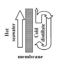
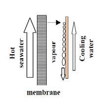
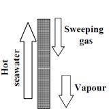
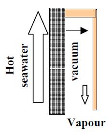
13 Basic Configuration of MD modules Direct Contact MD Air Gap MD Seeping Gas MD Vacuum MD 13
14 MD Research Activities at KFUPM 14
15 Undergraduate Students Work Sep.2012 to Sep
 flow Q (l/min) Renolds No# pressure drop (pa) 1 0.55556 1 2,554.378 42.554 2 1.")
16 Design of Module Criteria considered Pressure losses Good level of turbulence 1 st channel width 10 mm dimensions in m Temperature 20 width = 1.00E-02 depth = 3.00E-03 length = 3.00E-01 Perimeter = friction factor = D-hydrulic= density= viscosity= 1.002E-03 Area= # V (m/s) flow Q (l/min) Renolds No# pressure drop (pa) , , , , , , , , , , , , , , , , , , , , , , , , , , nd 16

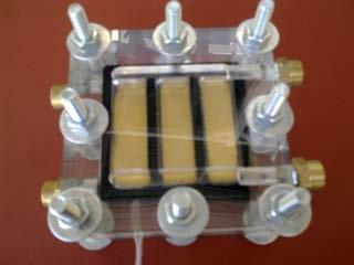
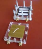
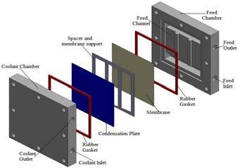
17 AGMD Cell 17

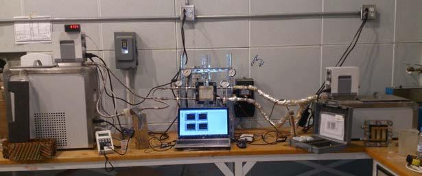
18 The MD setup and module 18
19 Effect of feed flow rate 80.0 Permeate flux (kg/m2 h) Feed flow rate (L/min) 2 mm gap 5 mm gap Th = 70 C Tc = 30 C Qc = 8 L/min TDS = 2400 mg/l 19

20 Effect of Feed Water Salinity [g/l] on permeate flux 20
21 Academic year Objective: get into details University funded project Theoretical analysis to predict the flux Design of the MD module and System Benchmark experimental data 21


22 . Theoretical Analysis: DCMD Mass Transfer OR p wf exp. T mf p wp exp. T mp Antoine equation 22

23 . Heat Transfer 23


24 Heat & Mass Transfer in DCMD... 24

25 Modelling Results for DCMD. Flux vs. feed temperature in DCMD. Permeate temperature is 21 0 C; feed flow rate is 12 L/min and permeate flow rate is 4 L/min. No salt concentration. 25

26 Modelling Results for DCMD. permeate flow rate is 3 L/min, feed temperature is 60 C, permeate temperature is 21 C. 26
27 . Modelling Results for AGMD Model (45 oc) Liu et al (45 oc) Model (35 oc) Liu et al (35 oc) Flux (kg/m2h) Air gap thickness (mm) Effect of the air gap thickness at feed flow rate (16 L/min), coolant flow rate (16 L/min) at different feed temperature (45 and 35) C, and coolant temperature (20 C). 27
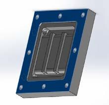
28 Improving the Design of MD system: Prevent internal leakage Easy to assemble Easy to control (flow, temp., pressure,.) Use different material Structural support to hold the system Sensors (flow, temperature, pressure, power, E. conductivity, etc.) Data Acquisition System with labview software. Optimization of the operating conditions 28

29 Other designs 29
30 30
31 Schematic Diagram Of The Experimental Setup 31

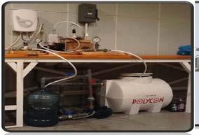
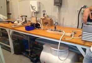
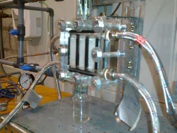
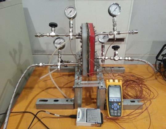
32 The Actual Laboratory Setup 32

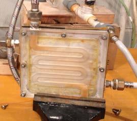
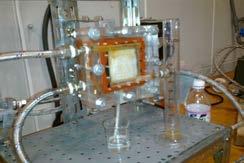
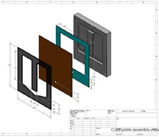
33 The Connected MD Module 33
34 Samples of results: AGMD Permeate Flux [Kg/m2hr] Effect of feed temperature and gap width 3mm, Theo. 5mm, Theo. 7mm, Theo. 3mm, Exp. 5mm, Exp. 7mm, Exp Feed Temperature [0C] coolant temperature of 30 C, feed flow rate of 3L/min and coolant flow rate of 3 L/min. 34
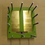
35 Samples of results: AGMD Effect of Feed solution concentration 17.54% drop in flux coolant temperature of 30 C, feed flow rate of 3L/min, coolant flow rate of 3 L/min and air gap width of 3mm. 35
 236 ± 6 379 ± 8 ε (%) 75.9 ± 5.4 79.7 ± 8.7 θ (º) active layer 138.3 ± 2.4 139.0 ± 2.8 θ (º) support layer 121.4 ± 3.4 119.3 ± 1.0 36")
36 Membrane Pore size Properties PTFE 0.22 μm PTFE 0.45 μm δ full membrane (μm) ± ± 13.6 δ teflon (μm) 7.9 ± ± 2.0 δ support (μm) ± ± 15.8 d p (nm) 236 ± ± 8 ε (%) 75.9 ± ± 8.7 θ (º) active layer ± ± 2.8 θ (º) support layer ± ±
37 Membrane Degradation Test Samples of results: AGMD 26% reduction in flux over 38 hours of operation (no pre-treatment of seawater) feed temperature of 70 C, coolant temperature of 20 C, coolant flow rate of 3 L/min, feed flow rate of 3 L/min and air gap width of 3mm.The feed solution is seawater having TDS of 60g/L. 37
38 Membrane Degradation Test Samples of results: AGMD Above 99.95% feed temperature of 70 C, coolant temperature of 20 C, coolant flow rate of 3 L/min, feed flow rate of 3 L/min and air gap width of 3mm.The feed solution is seawater having TDS of 60g/L. 38

39 Direct Contact MD 39
40 Samples of results: DCMD 120 Flux kg/m2-hr) Experimental at 5 oc Experimental at 10 oc Experimental at 15 oc Experimental at 20 oc Experimental at 25 oc Predicted at 5 oc Predicted at 10 oc Predicted at 15 o C Predicted at 20 oc Feed Temperature (C) Predicted at 25 oc 40
41 Samples of results: DCMD FLux (kg/m2-hr) Predicted at 90 oc Predicted at 70 oc Predicted at 50 oc Experimental at 90 oc Experimental at 70 oc Experimental at 50 oc Coolant Temperature (C) 41

42 Water and Air Gap Membrane Distillation 42

43 Water and Air Gap Membrane Distillation: Module Assembly 43


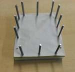
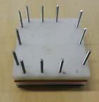
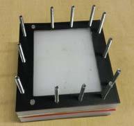
44 Water and Air gap Module Assembly 44
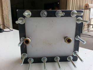
45 Instrumented Module 45
46 80 Samples of results: Water and Air Gap Permeate flux [kg/m2.hr] Air Gap water Gap % increase in flux with water gap Feed Temperature [ᵒC] Feed Temperature [ᵒC] Khalifa A., Water and Air Gap Membrane Distillation for Water Desalination - An Experimental Comparative Study, Separation and Purification Technology 141 (2015)
47 Samples of results: Water and Air Gap permeate Flux [kg/ m2.hr] Air gap - 8 mm width Water gap - 8 mm width Air Gap - 4 mm width Water Gap - 4 mm width Feed water Temperature [ C] 47
48 Conclusions The membrane distillation (MD) technique is promising It is easy to apply, and with compact design. Low energy consumption. Solar energy utilization enhances its potential. Good flux output. Still there is a room for improvement. 48
49 The Future Work Objective: To contribute in developing the MD systems Using the solar energy with MD Multi-stage module Energy recovery and optimization Advanced modeling 49