Second Generation PEM Fuel Cells and the Indirect Reduction of Oxygen
|
|
|
- Baldric Barber
- 5 years ago
- Views:
Transcription


1 Second Generation PEM Fuel Cells and the Indirect Reduction of Oxygen Trevor Davies, University of Chester FCH2 2015, 21 st May 2015

2 PEM Fuel Cell Market Predictions
3 Outline Conventional PEM fuel cells Challenges Direct reduction of O 2 Redox Flow Batteries H 2 -Br 2 Regenerative PEM fuel cells In-direct reduction of O 2 Low cost Durable
4 Conventional PEM Fuel Cells
5 Conventional PEM Fuel Cell e - Pt Cathode Air, Water Vapour & Heat Excess Fuel Out H + Membrane H + H + Fuel In Air Advances in Chemical Engineering, 41, 2012, 65 Pt Anode Blower or Compressor 5
6 The Problem Direct reduction of oxygen Difficult reaction requires high Pt loading Causes durability issues US Drive: Fuel Cell Technical Team Roadmap, June 2013
7 Platinum Recent US DoE analysis: Pt contributes ~17% of total cost of 80 kw PEMFC system 2012 technology + mass production Toyota PEMFC vehicle launch: 66,000 + VAT per car (Germany) 30 g Pt loading >3% of car cost
8 Platinum HOR Pt best metal for HOR Kinetics are very fast simple reaction Voltage losses are very small <5 mv for 0.05 mg cm -2 * * J. Electrochem. Soc., 157 (2007) B631
9 Platinum - ORR Pt is the best metal for the OOR Kinetics are slow More Pt required for ORR Complicated reaction with numerous pathways 2e vs. 4e Voltage losses are very large More than half of the voltage loss for PEMFC * * J. Electrochem. Soc., 157 (2010) B1529
10 Reduction Pathway Oxygen Reduction Reaction E o O 2 + e - + H + HO V HO 2 + e - + H + H 2 O 2 H 2 O 2 + e - + H + HO + H 2 O HO + e - + H + H 2 O O e H + H 2 O 2 H 2 O e H + 2 H 2 O O e H + 2 H 2 O +1.4 V V V V V V
11 Pt Reaction Selectivity Undesirable side products cause durability issues Presence of H 2 O 2 is highly damaging

12 Start Up Durability Issues
13 Cooling Engineering challenge for conventional PEM fuel cells Limited to ~80 o C difficult to dissipate waste heat Need higher operating temperatures
14 Conventional PEMFC Technology Challenges Direct reduction of oxygen Slow kinetics cause large voltage drop High Pt loading Degradation via by-products Start up issues Cooling issues due to 80 o C max temperature
15 Redox Flow Batteries
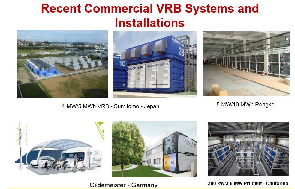
16
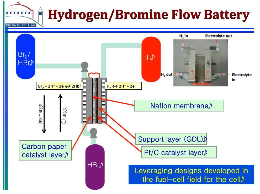
17 Hydrogen/Bromine Flow Battery
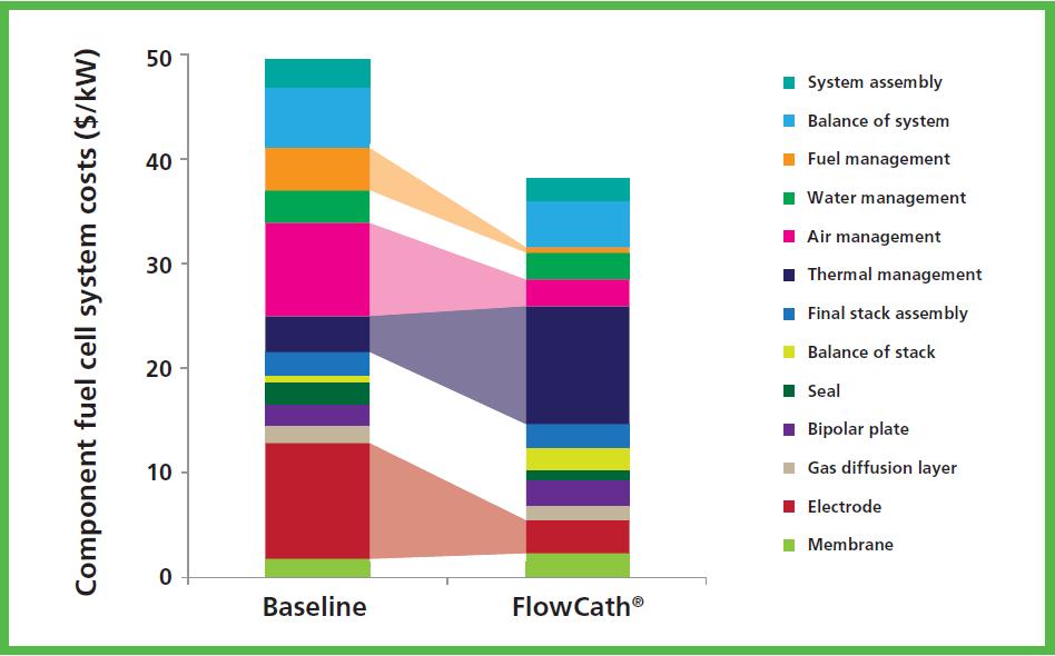
18 Performance A. Weber, IFBF 2013, Dublin
19 Regenerative PEM Fuel Cells In-Direct O 2 Reduction
20 Regenerative PEMFC Technology Challenges Direct reduction of oxygen Slow kinetics cause large voltage drop High Pt loading Degradation via by-products Start up issues Cooling issues due to 80 o C max temperature Solution In-direct reduction of oxygen No Pt required Durability issues resolved

21 ACAL Energy Concept Liquid Phase Catalyst/Mediator to Drive Fuel Cell


22 Liquid Flow Porous electrode Basic Cell 22 Architecture Standard cell components Fuel cell flow battery hybrid Anode very similar to conventional PEMFC Cathode similar to redox flow battery Optimization needed Same fuels as standard PEM Hydrogen, reformate and methanol evaluated
")

23 Polyoxometallates (POMs) Keggin structures form a category of POMs Best known example is PMA (Aldrich) Inorganic complexes Stable Electrochemically reduced at carbon electrode Reduced keggin reacts with oxygen [PMo 12 O 40 ] 3-
24 POM Electrochemistry 0.5 mm (n-bu4n) 4 [PVMo 11 O 40 ] in 0.1 M HClO 4 /MeCN/water Glassy carbon working electrode [PVMo 11 O 40 ] 4- Keggin J. Electroanal. Chem. 451 (1998) 203
![POM Electrochemistry [P 2 V 2 W 16 O 62 ] 8- Dawson 0.](/docs-images/94/122334362/images/25-1.jpg "2 mm [P 2 V 2 W 16 O 62 ] 8- in aqueous media Glassy carbon working electrode C.")
25 POM Electrochemistry [P 2 V 2 W 16 O 62 ] 8- Dawson 0.2 mm [P 2 V 2 W 16 O 62 ] 8- in aqueous media Glassy carbon working electrode C. R. Chimie, 8 (2005) 1057
26

27 Fundamentally More Durable Hydrogen or Reformate Fuel Anode Basic Theory of Operation H + H + H + e - Proton Exchange Membrane Cathode Proprietary Catalyst Solution Pump Regenerator Air, Water Vapor, Heat Blower Air Catalyst system thermodynamically stable High operational durability Reaction with oxygen occurs away from electrode No oxygen or peroxide in contact with electrode or membrane to cause damage Membrane in contact with aqueous solution Membrane always hydrated 27
28
29 Cooling Regenerative fuel cells can operate above 80 o C Cathode side of membrane is always wet Membrane drying can be avoided Big impact on cooling Catholyte acts as a coolant
30 A New Set of Challenges Cell optimization, scale up and stack assembly Flow battery vs. fuel cell architecture Liquid catalyst formulation High electrode potential vs. fast regeneration reaction Bubble generation High surface area bubbles vs. high efficiency bubbling The bubbler performance and catalyst chemistry determine the volume of catholyte required >100 o C operation 10,000 hours durability achieved at o C Oxygen concentration vs. regeneration kinetics
31 Innovation Ford invited (and patented) the regenerative fuel cell concept in the 1980s Despite a wealth of resources, Ford could not achieve adequate current densities Over the last 10 years major advances have been achieved by a small company on a limited budget Why?
32 Innovation vs. Structure Innovativity Structure
33 Thank you
34 Backup Slides

35
36 Performance Charge-discharge curves Coulombic efficiency Electrical efficiency
37 Performance

38 Conventional PEM Fuel Cell Weaknesses Excess Fuel Out e - H + Pt Cathode Air, Water Vapour & Heat Too Costly High platinum content Expensive balance of plant Poor durability Membrane and catalyst suffer degradation Membrane Fuel In H + H + Development cycle for catalyst requires durability effort to be repeated for each development Large task for auto companies Air Pt Anode Blower or Compressor Membrane Cathode Platinum agglomeration is key reliability issue - Japanese Auto Maker 38

39
40