THERMAL AND HYDRAULIC MACHINES UNIT 2
|
|
|
- Lily Short
- 5 years ago
- Views:
Transcription
1 THERMAL AND HYDRAULIC MACHINES UNIT 2
2 A steam turbine is a device that extracts thermal energy from pressurized steam and uses it to do mechanical work on a rotating output shaft. Its modern manifestation was invented by Sir Charles Parsons in 1884.
3 Steam Turbine may also be define as a device which converts heat energy of to the steam to the mechanical energy which finally converted into electrical energy.
4 Because the turbine generates rotary motion, it is particularly suited to be used to drive an electrical generator about 90% of all electricity generation in the United States, is by use of steam turbines. The steam turbine is a form of heat engine that derives much of its improvement in thermodynamic efficiency through the use of multiple stages in the expansion of the steam, which results in a closer approach to the ideal reversible process.
5 Steam turbines are made in a variety of sizes ranging from small <0.75 kw units used as mechanical drives for pumps, compressors and other shaft driven equipment, to 1,500 MW turbines used to generate electricity. There are several classifications for modern steam turbines.
6 WORK IN A TURBINE VISUALIZED
7 Further the steam turbine is based upon Rankine cycle An ideal Rankine cycle operates between pressures of 30 kpa and 6 MPa. The temperature of the steam at the inlet of the turbine is 550 C. Find the net work for the cycle and the thermal efficiency. W net =W turbine -W pump OR Q in -Q out Thermal efficiency h th =W net /Q in Net work done is converted into power output of turbine.
8 Ideal Rankine Cycle This cycle follows the idea of the Carnot cycle but can be practically implemented. 1-2 isentropic pump 2-3 constant pressure heat addition 3-4 isentropic turbine 4-1 constant pressure heat rejection
9 CLASSIFICATION OF STEAM TURBINE Classification of steam turbines may be done as following: 1. According to action of steam (a) Impulse turbine (b) Reaction turbine (c) Combination of both
10 2. According to direction of flow: (a) Axial flow turbine (b) Radial flow turbine 3. According to number of stages (a) Single stage turbine (b) Multi stage turbine (4). According to number of cylinders (a) Single cylinder turbine (b) Double cylinder turbine (c) Three cylinder turbine
11 (5)According to steam pressure at inlet of Turbine: (a) Low pressure turbine (b) Medium pressure turbine. (c) High pressure turbine (d) Super critical pressure turbine. (6)According to method of governing: (a) Throttle governing turbine. (b) Nozzle governing turbine. (c) By pass governing turbine.
12 (7) According to usage in industry: (a) Stationary turbine with constant speed. (b) Stationary turbine with variable speed. (c) Non stationary turbines.
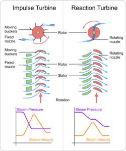
13 Description of common ty. of Turbines. The common ty. of steam turbine are 1. Impulse Turbine. 2. Reaction Turbine. The main difference between these two turbines lies in the way of expanding the steam while it moves through them.
14 In the impulse turbine, the steam expands in the nozzles and it's pressure does not alter as it moves over the blades. In the reaction turbine the steam expanded continuously as it passes over the blades and thus there is gradually fall in the pressure during expansion below the atmospheric pressure.
15 PRESSURE-VELOCITY DIAGRAM FOR A TURBINE NOZZLE PRESSURE ENTRANCE HIGH THERMAL ENERGY HIGH PRESSURE LOW VELOCITY STEAM INLET EXIT LOW THERMAL ENERGY LOW PRESSURE HIGH VELOCITY STEAM EXHAUST VELOCITY
16 Simple impulse Turbine. It the impulse turbine, the steam expanded within the nozzle and there is no any change in the steam pressure as it passes over the blades
17 IMPULSE TURBINE PRINCIPLE ROTOR NOZZLE STEAM CHEST
18
19 PRESSURE-VELOCITY DIAGRAM FOR A MOVING IMPULSE BLADE DIRECTION OF SPIN REPRESENTS MOVING IMPULSE BLADES PRESSURE TURBINE SHAFT ENTRANCE HIGH VELOCITY STEAM INLET EXIT LOW VELOCITY STEAM EXHAUST VELOCITY
20 Reaction Turbine In this type of turbine, there is a gradual pressure drop and takes place continuously over the fixed and moving blades. The rotation of the shaft and drum, which carrying the blades is the result of both impulse and reactive force in the steam. The reaction turbine consist of a row of stationary blades and the following row of moving blades
21 The fixed blades act as a nozzle which are attached inside the cylinder and the moving blades are fixed with the rotor as shown in figure When the steam expands over the blades there is gradual increase in volume and decrease in pressure. But the velocity decrease in the moving blades and increases in fixed blades with change of direction.
22 Because of the pressure drops in each stage, the number of stages required in a reaction turbine is much greater than in a impulse turbine of same capacity. It also concluded that as the volume of steam increases at lower pressures therefore the diameter of the turbine must increase after each group of blade rings.
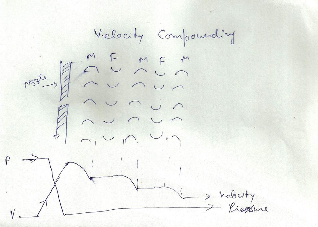
23 REACTION TURBINE PRINCIPLE ROTOR STEAM CHEST
24
25 PRESSURE-VELOCITY DIAGRAM FOR A MOVING REACTION BLADE DIRECTION OF SPIN REPRESENTS MOVING REACTION BLADES TURBINE SHAFT ENTRANCE HIGH PRESSURE HIGH VELOCITY STEAM INLET EXIT LOW PRESSURE LOW VELOCITY STEAM EXHAUST PRESSURE VELOCITY
26
27 .Compounding in Steam Turbine. The compounding is the way of reducing the wheel or rotor speed of the turbine to optimum value. It may be defined as the process of arranging the expansion of steam or the utilization of kinetic energy or both in several rings.
28 There are several methods of reducing the speed of rotor to lower value. All these methods utilize a multiple system of rotors in series keyed on a common shaft, and the seam pressure or jet velocity is absorbed in stages as the steam flower over the blades.
29 Different methods of compounding are: 1.Velocity Compounding 2.Pressure Compounding 3.Pressure Velocity Compounding. These are explained in detail as given below:
30 Velocity Compounding: There are number of moving blades separated by rings of fixed blades as shown in the figure. All the moving blades are keyed on a common shaft. When the steam passed through the nozzles where it is expanded to condenser pressure. It's Velocity becomes very high. This high velocity steam then passes through a series of moving and fixed blades
31 When the steam passes over the moving blades it's velocity decreases. The function of the fixed blades is to re-direct the steam flow without altering it's velocity to the following next row moving blades where a work is done on them and steam leaves the turbine with allow velocity as shown in diagram.
32 VELOCITY COMPOUNDED TURBINE
33
34 Pressure Compounding: These are the rings of moving blades which are keyed on a same shaft in series, are separated by the rings of fixed nozzles. The steam at boiler pressure enters the first set of nozzles and expanded partially. The kinetic energy of the steam thus obtained is absorbed by moving blades.
35 The steam is then expanded partially in second set of nozzles where it's pressure again falls and the velocity increase the kinetic energy so obtained is absorbed by second ring of moving blades.
36 This process repeats again and again and at last, steam leaves the turbine at low velocity and pressure. During entire process, the pressure decrease continuously but the velocity fluctuate as shown in diagram.
37 PRESSURE COMPOUNDED TURBINE
38
39 Pressure velocity compounding This method of compounding is the combination of two previously discussed methods. The total drop in steam pressure is divided into stages and the velocity obtained in each stage is also compounded. The rings of nozzles are fixed at the beginning of each stage and pressure remains constant during each stage as shown in figure.
40 The turbine employing this method of compounding may be said to combine many of the advantages of both pressure and velocity staging By allowing a bigger pressure drop in each stage, less number stages are necessary and hence a shorter turbine will be obtained for a given pressure drop.
41 PRESSURE-VELOCITY COMPOUNDED IMPULSE TURBINE CURTIS STAGE NOZZLE, MOVING BLADE, FIXED BLADE, AND MOVING BLADE NOZZLE MOVING BLADE FIXED BLADE MOVING BLADE RATEAU STAGE NOZZLE & MOVING BLADE NOZZLE MOVING BLADE PRESSURE VELOCITY
42
43 Steam supply and exhaust conditions These ty. include condensing, noncondensing, reheat, extraction and induction. Condensing turbines are most commonly found in electrical power plants. These turbines exhaust steam in a partially condensed state, typically of a quality near 90%, at a pressure well below atmospheric to a condenser.
44 Non-condensing or back pressure turbines are most widely used for process steam applications. The exhaust pressure is controlled by a regulating valve to suit the needs of the process steam pressure. These are commonly found at refineries, heating units, pulp and paper plants, and desalination facilities where large amounts of low pressure process steam are available.
45 Reheat turbines are also used almost exclusively in electrical power plants. In a reheat turbine, steam flow exits from a high pressure section of the turbine and is returned to the boiler where additional superheat is added. The steam then goes back into an intermediate pressure section of the turbine and continues its expansion.
46 Extracting type turbines are common in all applications. In an extracting type turbine, steam is released from various stages of the turbine, and used for industrial process needs or sent to boiler feedwater heaters to improve overall cycle efficiency. Extraction flows may be controlled with a valve, or left uncontrolled.
47 Induction turbines introduce low pressure steam at an intermediate stage to produce additional power.
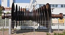
48 Casing or shaft arrangements These arrangements include single casing, tandem compound and cross compound turbines. Single casing units are the most basic style where a single casing and shaft are coupled to a generator. Tandem compound are used where two or more casings are directly coupled together to drive a single generator.
49 A cross compound turbine arrangement features two or more shafts not in line driving two or more generators that often operate at different speeds. A cross compound turbine is typically used for many large applications.
50 Two-flow rotors A two-flow turbine rotor. The steam enters in the middle of the shaft, and exits at each end, balancing the axial force. The moving steam imparts both a tangential and axial thrust on the turbine shaft, but the axial thrust in a simple turbine is unopposed. To maintain the correct rotor position and balancing, this force must be counteracted by an opposing force.
51 Either thrust bearings can be used for the shaft bearings, or the rotor can be designed so that the steam enters in the middle of the shaft and exits at both ends. The blades in each half face opposite ways, so that the axial forces negate each other but the tangential forces act together. This design of rotor is called two-flow or doubleexhaust.
52
53 Principle of operation and design An ideal steam turbine is considered to be an isentropic process, or constant entropy process, in which the entropy of the steam entering the turbine is equal to the entropy of the steam leaving the turbine
54 No steam turbine is truly isentropic, however, with typical isentropic efficiencies ranging from 20 90% based on the application of the turbine.
55 The interior of a turbine comprises several sets of blades, or buckets as they are more commonly referred to. One set of stationary blades is connected to the casing and one set of rotating blades is connected to the shaft.
56 The sets intermesh with certain minimum clearances, with the size and configuration of sets varying to efficiently exploit the expansion of steam at each stage.
57 Turbine efficiency Schematic diagram outlining the difference between an impulse and a 50% reaction turbine To maximize turbine efficiency the steam is expanded, doing work, in a number of stages. These stages are characterized by how the energy is extracted from them and are known as either impulse or reaction turbines.
58 Most steam turbines use a mixture of the reaction and impulse designs: each stage behaves as either one or the other, but the overall turbine uses both. Typically, higher pressure sections are impulse type and lower pressure stages are reaction type.
59 Impulse turbines An impulse turbine has fixed nozzles that orient the steam flow into high speed jets. These jets contain significant kinetic energy, which is converted into shaft rotation by the bucket-like shaped rotor blades, as the steam jet changes direction.
60 A pressure drop occurs across only the stationary blades, with a net increase in steam velocity across the stage. As the steam flows through the nozzle its pressure falls from inlet pressure to the exit pressure (atmospheric pressure, or more usually, the condenser vacuum). Due to this high ratio of expansion of steam, the steam leaves the nozzle with a very high velocity.
61 The steam leaving the moving blades has a large portion of the maximum velocity of the steam when leaving the nozzle. The loss of energy due to this higher exit velocity is commonly called the carry over velocity or leaving loss.
62 Reaction turbines In the reaction turbine, the rotor blades themselves are arranged to form convergent nozzles. This type of turbine makes use of the reaction force produced as the steam accelerates through the nozzles formed by the rotor.
63 Steam is directed onto the rotor by the fixed vanes of the stator. It leaves the stator as a jet that fills the entire circumference of the rotor. The steam then changes direction and increases its speed relative to the speed of the blades.
64 A pressure drop occurs across both the stator and the rotor, with steam accelerating through the stator and decelerating through the rotor, with no net change in steam velocity across the stage but with a decrease in both pressure and temperature, reflecting the work performed in the driving of the rotor.
65 Operation and maintenance When warming up a steam turbine for use, the main steam stop valves (after the boiler) have a bypass line to allow superheated steam to slowly bypass the valve and proceed to heat up the lines in the system along with the steam turbine. Also, a turning gear is engaged when there is no steam to the turbine to slowly rotate the turbine to ensure even heating to prevent uneven expansion.
66 After first rotating the turbine by the turning gear, allowing time for the rotor to assume a straight plane (no bowing), then the turning gear is disengaged and steam is admitted to the turbine, first to the astern blades then to the ahead blades slowly rotating the turbine at RPM ( Hz) to slowly warm the turbine.
67 Any imbalance of the rotor can lead to vibration, which in extreme cases can lead to a blade breaking away from the rotor at high velocity and being ejected directly through the casing. To minimize risk it is essential that the turbine be very well balanced and turned with dry steam - that is, superheated steam with a minimal liquid water content
68 . If water gets into the steam and is blasted onto the blades (moisture carry over), rapid impingement and erosion of the blades can occur leading to imbalance and catastrophic failure. Also, water entering the blades will result in the destruction of the thrust bearing for the turbine shaft.
69 To prevent this, along with controls and baffles in the boilers to ensure high quality steam, condensate drains are installed in the steam piping leading to the turbine. Modern designs are sufficiently refined that problems with turbines are rare and maintenance requirements are relatively small.
70 The steam turbine operates on basic principles of thermodynamics using the part of the Rankine cycle. Superheated vapor (or dry saturated vapor, depending on application) enters the turbine, after it having exited the boiler, at high temperature and high pressure. The high heat/pressure steam is converted into kinetic energy using a nozzle. Once the steam has exited the nozzle it is moving at high velocity and is sent to the blades of the turbine.
71 A force is created on the blades due to the pressure of the vapor on the blades causing them to move. A generator or other such device can be placed on the shaft, and the energy that was in the vapor can now be stored and used.
72 The gas exits the turbine as a saturated vapor (or liquid-vapor mix depending on application) at a lower temperature and pressure than it entered with and is sent to the condenser to be cooled
73 Isentropic turbine efficiency To measure how well a turbine is performing we can look at its isentropic efficiency. This compares the actual performance of the turbine with the performance that would be achieved by an ideal, isentropic, turbine. When calculating this efficiency, heat lost to the surroundings is assumed to be zero.
74 The starting pressure and temperature is the same for both the actual and the ideal turbines, but at turbine exit the energy content ('specific enthalpy') for the actual turbine is greater than that for the ideal turbine because of irreversibility in the actual turbine.
75 The isentropic efficiency is found by dividing the actual work by the ideal work. where h 1 is the specific enthalpy at state one h 2 is the specific enthalpy at state two for the actual turbine h 2s is the specific enthalpy at state two for the isentropic turbine
76 INTRODUCTION A gas turbine is a machine delivering mechanical power or thrust. It does this using a gaseous working fluid. The mechanical power generated can be used by, for example, an industrial device. The outgoing gaseous fluid can be used to generate thrust. In the gas turbine, there is a continuous flow of the working fluid.
77 Cont This working fluid is initially compressed in the compressor. It is then heated in the combustion chamber. Finally, it goes through the turbine. The turbine converts the energy of the gas into mechanical work. Part of this work is used to drive the compressor. The remaining part is known as the net work of the gas turbine.
78 History of gas turbines We can distinguish two important types of gas turbines. There are industrial gas turbines and there are jet engine gas turbines. Industrial gas turbines were developed rather slowly. This was because, to use a gas turbine, a high initial compression is necessary. This rather troubled early engineers. Due to this, the first working gas turbine was only made in 1905 by the Frenchman Rateau.
79 Cont. The first gas turbine for power generation became operational in 1939 in Switzerland. It was developed by the company Brown Boveri. Gas turbines had a rather low thermal efficiency. But they were still useful. This was because they could start up rather quickly. They were therefore used to provide power at peak loads in the electricity network. In the 1980 s, natural gas made its breakthrough as fuel. Since then, gas turbines have increased in popularity. After world war 2, the gas turbine developed rapidly.
80 Cont New high-temperature materials, new cooling techniques and research in aerodynamics strongly improved the efficiency of the jet engine. It therefore soon became the primary choice for many applications. Currently, there are several companies producing gas turbines. The biggest producer of both industrial gas turbines and jet engines is General Electric (GE) from the USA. Rolls Royce and Pratt & Whitney are also important manufacturers of jet engines.
81 The ideal gas turbine cycle
82 Cont The cycle that is present is known as the Joule-Brayton cycle. This cycle consists of four important points. We start at position 1where the gas has passed through the inlet, after that the gas then passes through the compressor. We assume that the compression is performed isentropically. So, s1 = s2. The gas is then heated in the combustor. (Point 3.) This is done isobarically (at constant pressure). So, p2 = p3. Finally, the gas is expanded in the turbine. (Point 4.) This is again done isentropic ally. So, s3 = s4.
83 Cont The whole process is visualized in the temperatureentropy diagram as shown above. The cycle consists of an isentropic compression of the gas from state 1 to state 2; a constant pressure heat addition to state 3; an isentropic expansion to state 4, in which work is done; and an isobaric closure of the cycle back to state 1. Above Figure shows, a compressor is connected to a turbine by a rotating shaft. The shaft transmits the power necessary to drive the compressor and delivers the balance to a power-utilizing load, such as an electrical generator.
84 Cont When examining the gas turbine cycle, we do make a few assumptions. We assume that the working fluid is a perfect gas with constant specific heats cp and cv. Also, the specific heat ratio k (sometimes also denoted by ) is constant. We also assume that the kinetic/potential energy of the working fluid does not vary along the gas turbine. Finally, pressure losses, mechanical losses and other kinds of losses are ignored.
85 Classification The gas turbine can be classified into two categories, i.e. impulse gas turbine and reaction gas turbine. If the entire pressure drop of the turbine occurs across the fixed blades, the design is impulse type, while if the drop is taken place in the moving blades, the fixed blades serving only as deflectors, the design is called reaction type.
86 Cont The advantage of the impulse design is that there is no pressure force tending to move the wheel in the axial direction and no special thrust balancing arrangement is required. There being no tendency for gas to leak over the tips of the moving blades. A purely reaction turbine is not generally used. In a small multi-stage construction the velocity change in the moving and fixed blades is about the same, the design being 50% reaction types.
87 GAS TURBINE POWER PLANT The simple gas turbine power plant mainly consists of a gas turbine coupled to a rotary type air compressor and a combustor or combustion chamber which is placed between the compressor and turbine in the fuel circuit. Auxillaries, such as cooling fan, water pumps, etc. and the generator itself, are also driven by the turbine. Other auxillaries are starting device, lubrication system, duct system, etc. A modified plant may have in addition to the above, an inter-cooler, a regenerator and a reheater. The arrangement of a simple gas turbine power plant is shown in Figure in next slide
88 Schematic Arrangement of a Simple Gas Turbine Power Plant
89 Construction The basic construction of a gas turbine employs vanes or blades mounted on a shaft and enclosed in a casing. The flow of fluid through turbine in most designs is axial and tangential to the rotor at a nearly constant or increasing radius. There are two types of blades used in all turbines : those that are fixed on the rotor and move with the shaft and those that are fixed to the casing and help to guide and accelerate or decelerate the flow of fluid, being called fixed blades or vanes.
90 Cont The power of the turbine depends upon the size, shape and the speed of the blades used. Multi-staging is employed to increase the power output of the turbine by placing additional sets of fixed and moving blades in series. To prevent leakage of gas along the shaft gas seals or glands are provided where the shaft emerges from the turbine casing. The extending lengths of the shaft on the two sides of the turbine are supported on journal bearings which also maintain it s proper alignment.
91 Accessories There are several accessories fitted to the turbine. These are : a tachometer driven through a gear box, an over speed governor, a lubricating oil pump and a fuel regulator. The starting gear is mounted on the shaft at one end. The tachometer shows the speed of the machine and also actuates the fuel regulator in case of speed rises above or fall below the regulated speed, so that the fuel regulator admits less fuel or more fuel into the combustor and varies the turbine power according to demand of load.
92 Cont The governor back off fuel feed, if the exhaust temperature from turbine exceeds the safe limit, thermal switches at the turbine exhaust acting on fuel control to maintain present maximum temperature. The lubricating pump supplies oil to bearing under pressure. Other auxillaries used on the turbine plant include the starting motor or engine with starting gear, oil coolers, filters and inlet and exhaust mufflers. The turbine (and with it the compressors) is driven by the starting motor through a clutch and set-up gearing. A standby motor driven pump is also provided for emergency service. A failure of lubricating pump system results in stopping of the unit automatically.
93 Compressor A compressor is a device that is used to supply compressed air to the combustion chamber. Compressors are broadly classified as positive displacement type and rotodynamic type and may be of single stage or multi-stage design. In the positive displacement machine, successive volumes of air are pressurized within a closed space. These may be of reciprocating type or rotary type. In reciprocating type machines, air is compressed by a piston in a cylinder, while in the rotary type, this is accomplished by positive action of rotating elements.
94 Cont The roto-dynamic compressors may be of radial flow, axial flow or mixed flow type. In these machines, compression takes place by dynamic action of rotating vanes or impellers which impart velocity and pressure to the air as it flows through the compressor. Rotodynamic type compressors include the centrifugal, axial and mixed flow compressors which are all high speed machines running at as high as 3,000 to 4,000 RPM driven by turbines. These are designed to have high value of air discharge capacity at moderate pressure. These types of compressors are usually employed for gas turbine applications.
95 Combustor A combustor is a device inside which the combustion of fuel takes place. For an efficient operation of gas turbine plant, it is necessary to ensure good combustor performance. A good combustor should achieve completeness of fuel combustion and the lowest possible pressure drop in the gas, besides being compact, reliable and easy to control. Complete combustion of fuel depends upon three factors, viz. temperature, time and turbulence. Temperature in the combustor directly affects combustion and high temperature is conductive to rapid combustion.
96 Generator It is a device that generates electricity. It is coupled to the same shaft of turbine and runs at same speed to that of the turbine. The capacity of generators depends on installed capacity of the plant. The types of generators to be used depend on the purpose for which electrical energy is to be produced.
97 TYPES OF GAS TURBINE POWER PLANTS The gas turbine power plants can be classified mainly into two categories. These are :open cycle gas turbine power plant and closed cycle gas turbine power plant. Open Cycle Gas Turbine Power Plant In this type of plant the atmospheric air is charged into the combustor through a compressor and the exhaust of the turbine also discharge to the atmosphere. Closed Cycle Gas Turbine Power Plant In this type of power plant, the mass of air is constant or another suitable gas used as working medium, circulates through the cycle over and over again.
98 OPEN CYCLE GAS TURBINE POWER PLANTAND ITS CHARACTERISTICS The schematic arrangement of a simple open cycle gas turbine power plant is shown in Figure in next slide
99 SIMPLE OPEN GAS TURBINE POWER PLANT
100 Cont In the process shown the cycles are : 2-3: Isentropic compression 3-4: Heat addition at constant pressure 4-1: Isentropic expansion 1-2: Heat rejection at constant pressure The ideal thermal efficiency for the cycle,ç t, is given by, Heat supplied - Heat rejected/heat supplied where, r is the compression ratio=v2/v3and k is the ratio of specific heat of the gas.
101 Cont In actual operation the processes along 2-3 and 4-1 are never isentropic and the degree of irreversibility of these processes and the mechanical efficiencies of the machine components greatly reduce the ideal value of thermal efficiencies of the cycle. If the air entering the combustor is preheated by the heat of exhaust gases escaping from the turbine, some heat can be recovered resulting into an increase in the efficiency of the cycle improved. Such heating of combustion air is known as regeneration and the heat exchanger transferring heat from gas to air is called regenerator.
102 Cont Since most of the output of turbine is consumed by the compressor, the actual efficiency of the cycle greatly depends upon an efficient working of the compressor. To attain higher compression ratios, it is necessary to use multi-stage compression with inter-cooling. In actual practice, all these modifications, viz. regeneration, reheating and inter-cooling are combined in a simple modified cycle and a substantial gain in the overall plant efficiency is attained.
103 5 CLOSED CYCLE GAS TURBINE POWER PLANTAND ITS CHARACTERISTICS In the closed cycle, quantity of air is constant, or another suitable gas used as working medium, circulates through the cycle over and over again. Combustion products do not come in contact with the working fluid and, thus, remain closed.
104 Cont A development in the basic gas turbine cycle is the use of the closed cycle which permits a great deal of flexibility in the use of fuels. Moreover, working medium of the plant could be any suitable substance other than air which would give higher efficiency. An arrangement of closed gas turbine cycle is shown in Figure in next slide. In this cycle, working fluid is compressed through the requisite pressure ratio in the compressor, and fed into the heater, where it is heated up to the temperature of turbine itself.

105 Arrangement of Closed Cycle Gas Turbine Plant
106 CONT The fluid is then expanded in the turbine and the exhaust is cooled to the original temperature in the precooler. It then re-enter the compressor to begin the next cycle. Thus, the same working fluid circulates through the working parts of the system. The heater burns any suitable fuel and provides the heat for heating the working fluid. In fact, this combustor is akin to an ordinary boiler furnace, working at the atmosphere pressure and discharging the gaseous products to the atmosphere. There is, thus, a great deal of flexibility in respect of furnace design and use of fuel, allowing low cost fuel to be used.
107 Cont Another advantages in use of closed cycle is the choice of selecting a convenient pressure range, once the pressure ratio has been selected. The volume of the air or the working fluid in the cycle depends upon the pressure range which, in turn, affects the sizes of the air heater, compressor, turbine, etc. In a closed cycle, there is no restriction to keep the pressure low and this could be kept at any suitable value say 7.03 kg/cm2(68.9 N/cm ) abs.
108 Cont The pre-cooler in a closed cycle plant is an important equipment and corresponds to the condenser of a steam plant. However, unlike the condenser, cooling water in the pre-cooler could be heated to a fairly high temperature depending upon temperature of exit gas from the turbine, and then used elsewhere in the plant. The design of pre-cooler is commonly of the shell and tube type, and water is the coolant commonly used. The air heater of the closed cycle corresponds to the water heaters of the steam plant, but with one important difference that it has very small heat storage capacity.
109 FUEL FOR GAS TURBNE POWER PLANTS Natural gas is the ideal fuel for gas turbines, but this is not available everywhere. Blast furnace and producer gas may also be used for these plants. However, liquid fuels of petroleum origin, such as, distillate oils or residual oils are most commonly used for gas turbine power plants. The essential qualities of these fuels include proper volatility, viscosity and calorific value. At the same time, the fuel should be free from any content of moisture and suspended impurities that may clog the small passages of the nozzles and damage valves and plungers of the fuel pump.
110 Cont However, liquid fuels of petroleum origin, such distillate oils or residual oils are most commonly used for gas turbine plants. Residual oils burns with less ease than distillate oils and the heaters are often used to start the unit from cold, after which the residual oils are red into the combustor. Pre-heating of residual oils may be necessary in cold climates. Use of solid fuel, such as coal in pulverized form in gas turbines presents several difficulties, most of which have been only partially overcome.
111 Types of Gas Turbines Jet engines Air breathing jet engines are gas turbines optimized to produce thrust from the exhaust gases, or from ducted fans connected to the gas turbines. Jet engines that produce thrust from the direct impulse of exhaust gases are often called turbojets, whereas those that generate thrust with the addition of a ducted fan are often called turbofans or (rarely) fanjets. Gas turbines are also used in many liquid propellant rockets, the gas turbines are used to power a turbopump to permit the use of lightweight, low pressure tanks, which saves considerable dry mass.