Analysis and System Design of a Large Chiller Plant for Korea, with or without Thermal Storage
|
|
|
- Hilary Cannon
- 5 years ago
- Views:
Transcription
1 Analysis and System Design of a Large Chiller Plant for Korea, with or without Thermal Storage Christine Levin HVAC Designer Flack + Kurtz Consulting Engineers, LLP New York, New York Peter Simmonds Director of Advanced Technologies Flack + Kurtz Consulting Engineers, LLP New York, New York ABSTRACT A 625,600 ft2 (58,120 m2) office building with retail in South Korea has a total cooling load of 3,330 tons refrigeration (1 1,7 12 kw). In order to evaluate the most economical manner to provide cooling, a simulation program was used. Five different configurations of chiller plants were investigated; each configuration was carefully described so that the computer model was a good representation of the intended plants. This paper outlines the design and analysis procedure, and the results show the difference in energy consumption between the configurations. BACKGROUND A forty-story building with 625,600 ft2 (58,120 m2) net area - approximately 40% retail space and 60% office space -- is to be built in Seoul, South Korea. The majority of the building is of rather light construction, insulated metal panels with low-e glass in double-paned windows. The glazing area ranges from 95% in the retail spaces to 10-60% on various hcades of the office space. Design conditions include 50 ft2 (4.6 m2) per person occupancy, 25 CFM (12 L/s) per person ventilation air, and ~/ft2 ( w/m2) lights and equipment load for the retail areas. Corresponding conditions for the office areas are 50 ft2 (4.6 m2) per person, 15 CFM (7.1 Us) per person ventilation air, and a more modest 4.5 WI~? (48 w/m2) lights and equipment load. Seoul, South Korea, experiences summer and winter outdoor design conditions of 88 F (3 l.l C) db179"f (26. 1 C) wb and 1 1 F (-1 1.7"C) db respectively. The city's summers could be compared to Florida's for their heat and humidity, while its winters are colder than those ofnew York City. This paper will focus on design and analysis of cooling equipment, however, rather than considering heating as well. Because the location suffers fiom a shortage in electric capacity, indoor design conditions are set at 80 F (26.7"C) and 55% relative humidity (RH) in an effort to reduce the building's required cooling capacity. Furthermore, a local code requirement mandates that a maximum of 60% of the peak cooling load be satisfied by electricity. This leads to consideration of alternatives such as natural gas hels and use of thermal storage in the design and selection of the refrigeration plant. FAN SYSTEM DESCRIPTION The building is divided into two air distribution systems, retail and office, based on building geometry -- all retail spaces are grouped together in the lower floors of the building, while all office spaces are located on the upper floors -- and on operating schedules. Fan powered variable air volume (VAV) boxes, or powered induction units (PIU), were used to distribute and circulate air in both systems. "The PILJ system is basically just a VAV terminal box with a small fan that pulls some amount of air fiom a ceiling plenum. PWs have two functions: 1 1 to move warm air fiom a core area through the plenum to exterior zones requiring heat; this conserves heating energy, and 2) to provide increased air movement in zones normally served by VAV terminals; such zones often suffer fiom stagnant air when the primary air damper is in its minimum position. (DOE-2.1 Manual Supplement E Uudate, Systems p. 3.16)" The retail floors have mechanical rooms on the perimeter of the building, thus making air-side
2 economy cycles feasible. On cool days, outside air volumes greater than the minimum required amounts will be drawn into each floor's air handling unit to reduce the mechanical cooling capacity. On the office floors, however, mechanical rooms are located in the core, and ceiling plenum heights are so tight that air-side economy cycles are not feasible for these floors. Rather, water-side free cooling from the rooftop cooling towers is used as an economy measure for the office system. Based on the design conditions described previously and using the DOE-2.1E simulation program, the building was determined to have a cooling load of 3,330 tons refrigeration (11,712 kw). (Th' is was rounded up to 3,400 tons [I 1,958 kw for the purposes of sizing plant equipment.) The maximum daily integrated cooling load was found to be 39,283 ton-hours (138,158 kwh). For a graph of the summer design day cooling load profile for occupied hours, see Figure 1. CHILLER PLANT SCHEMES CONSIDERED Five different configurations of chiller plants were investigated for this project: A. Gas-Fired Absorption Chillers: To meet 100% of the building's cooling load, four (4) 850-ton gasfired absorption chillers were simulated. B. Two-Stage Steam Absorption Chillers: To meet 100% of the building's cooling load, four (4) 850-ton two-stage steam absorption chillers, with steam from gas-fired boilers, were simulated. C. Electric Centrifugal Chillers with Thermal Storage: Local code requires that a maximum of 60% of the peak cooling load be satisfied "real-time" by electricity. Therefore, two (2) 1,020-ton electric centrifugal chillers provided 2,040 tons refrigeration in this plant scheme. The remaining 1,360 tons required to cool the building (40% of the peak cooling load) were supplied by thermal storage -- circulating water through tanks of encapsulated ice generated at night. The 1,360-ton cooling supply rate for fourteen hours of building operation required 19,040 ton-hours of ice storage. The cooling storage rate required during the ten hours of nighttime tankcharging was 1,904 tons, well within the electric centrifugal chillers' capacity. D. Mixed Plant -- Gas-Fred Absorption Chillers and Thermal Storage: The fourth scheme considered was a mixed plant. 60% of the building's peak cooling load was provided by two (2) 1,020-ton gas-fired absorption chillers, while the remaining 40% was provided by thermal storage as in the previous scheme. Electric centrifugal chillers, two (2) at 950 tons each, were still required to charge the ice tanks at night, because gas-fired absorption chillers cannot make the 28 F (-2.2"C) glycol solution temperatures used to make the ice. E. Mixed Plant -- Gas-Fired Absorption Chillers, Electric Centrifugal Chillers. and Thermal Storage: The fifth scheme considered was also a mixed plant. 60% of the building's peak cooling load was provided by two (2) 1,020-ton gas-fired absorption chillers, 24% was provided by two (2) 408-ton electric centrifugal chillers, and thermal storage provided the remaining 16%. The 544-ton cooling supply rate for fourteen hours of building operation required 7,6 17 ton-hours of ice storage. The cooling storage rate required during the ten hours of nighttime tank-charging was 762 tons, well within the electric centrifugal chillers' 8 16-ton capacity. For a graph of this plant scheme's cooling capacity by source, see Figure 2. For a summary of the five chiller plant schemes considered, see Table 1. COMPUTER MODELING OF THE PLANTS In developing the computer models of the plants, the following DOE-2.1E equipment types were used: ABSORG-CHLR for the gas-fired absorption chillers, ABSOR2-CHLR for the two-stage steam absorption chillers, OPEN-CENT-CHLR for the electric centrifugal chillers, CTANK-STORAGE for the thermal storage component, and OPEN-TWR for the rooftop cooling towers. The quantity and capacities of the chillers were as described above. The ice tanks' storage capacities, cooling supply rates, and cooling storage rates were as also as described above. The cooling towers were specified at quantity eight (four units of two cells each) with sizes to be calculated by the simulation program. Operating efficiency curves for the equipment were left at the program defaults, but some equipment and plant parameters were changed to more closely model the intended plant designs. For example, to model a 25% glycol solution circulating in the ice tanks, CTANK-BASE-T and CTANK-T-RANGE were specified such that a 28 F (-2.2"C) temperature low would be allowed in the tank charging cycle.
3 The desired chilled water temperature was set at 44 F (6.7"C). The cooling towers' design wet bulb temperature was set at 79 F (26.1 "C) to agree with the summer design day's wet bulb temperature. Load assignments were specified such that the number of chillers running would be appropriate to the cooling load, thus maximizing plant efficiency and reducing operating costs. Finally, fuel and electricity meters set for each item of plant cooling equipment tallied the plants' energy consumption as distinct from the building's lights, electric equipment plug load, and fan system consumptions. RESULTS One of the major criteria for evaluating the various plant schemes under consideration was the cost of electricity and natural gas consumed over the course of a year. Using the DOE-2.1E simulation program, annual energy costs (for cooling only) were found to range from $420,335 for Plant Scheme C, Electric Centrifugal Chillers with Thermal Storage, to $530,0 13 for Plant Scheme B, Two-Stage Steam Absorption Chillers. For a summary of annual cooling energy consumption and costs of each chiller plant scheme, see Table 2. DISCUSSION In terms of annual cooling energy costs, the least expensive plant was Scheme C, Electric Centrifugal Chillers with Thermal Storage. This was surprising at first considering the monthly charge of $6.70 per kw of the year's peak electric demand, but evidently putting even 40% of the peak cooling load into thermal storage -- with electricity usage during offpeak nighttime hours at more favorable utility rates -- was enough to reduce the electric demand and associated charges to manageable levels. This scheme also has the advantage of lowest capital cost and least floor space required. However, in this area short on electric capacity, a blackout would cut out the majority of the building's cooling capacity. Emergency generators would only be sufficient to run circulation pumps for the ice tanks, not to run the electric chillers. The second least expensive plant to run was Scheme A, Gas-Fired Absorption Chillers. This scheme has the benefit of using natural gas as the power source rather than electricity. Also, choosing a chilled heater option in the gas-fired absorption units would provide heating in the winter from the same equipment, thus minimizing capital costs. However, disadvantages are that this scheme requires the largest floor area, and that it is often difficult to control the chemistry of the absorption cycle; crystallization of the lithium-bromide solution is always a concern. The third least expensive plant to run was Scheme E, Gas-Fired Absorption Chillers, Electric Centrifugal Chillers, with Thermal Storage, with a 60% / 24% / 16% contribution from each. As with plant schemes C and D, this plant's use of thermal storage shifts some electricity usage from peak daytime hours to off-peak nighttime hours and takes advantage of favorable utility rates. Scheme E's use of 16% thermal storage rather than 40% reduces the required electric centrifugal chiller sizes -- thus saving on capital costs - and also reduces the ice tank volume -- thus saving on real estate opportunity costs. Scheme E's use of natural gas as a partial power source is an improvement over scheme C's all-electric plant. And finally, unlike scheme D, scheme E's running of the electric centrifugal chillers during the day, rather than leaving them to stand idle, uses equipment that has already been paid for. The fourth least expensive plant to run was Scheme D, Gas-Fired Absorption Chillers with Thermal Storage from Electric Centrifugal Chillers. This scheme has the advantage of using electricity during off-peak hours and of having natural gas cooling available in case of blackouts. Emergency generators could make the thermal storage cooling available, too. However, this scheme has the disadvantage of high capital costs for two sets of chillers. And finally, the most expensive plant to run was Scheme B, Two-Stage Steam Absorption Chillers. Like the gas-fired absorption chillers, these have the benefit of using natural gas as the power source rather than electricity. Also, the same boilers used to produce steam for the steam absorption chillers can provide heating in the winter, thus minimizing capital costs. CONCLUSIONS Based on annual cooling energy costs alone, Scheme C, Electric Centrifugal Chillers with Thermal Storage would be the preferred plant scheme. However, other costs to consider are capital costs,
4 opportunity costs of mechanical space required, and operating costs such as labor, maintenance, insurance, And depreciation. All of the above could contribute to determination of a present worth dollar value for each plant scheme. However, there are also non-monetary considerations such as complexity of plant operation, versatility in plant power source, and local constraints such as utilities' capacity and reliability. It is these latter considerations that finally influenced the building owner to select Plant Scheme E, Gas- Fred Absorption Chillers, Electric Centrifugal Chillers, with Thermal Storage. In spite of the high capital costs associated with two sets of chillers, the large mechanical space required, and the complexity of operation, the cost and reliability of natural gas, the off-peak electric usage of thermal storage, and the versatility in power source of a mixed plant turned the scales in favor of Scheme E. ACKNOWLEDGMENTS The authors would like to acknowledge use of the DOE-2 simulation software, version 2. IE, developed by the Lawrence Berkeley Laboratory and by Hirsch & Associates under grants by the U.S. Department of Energy, the Southern California Edison Company, the Pacific Gas and Electric Company, the Electric Power Research Institute, the Gas Research Institute, Pacific Northwest Laboratory, and the IEA Solar Heating and Cooling Programme. REFERENCES Winkelmam, F.C., et al. DOE-2 Suvplement -- Version 2.1E. Berkeley, CA: Lawrence Berkeley Laboratory, 1993.

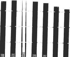
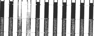

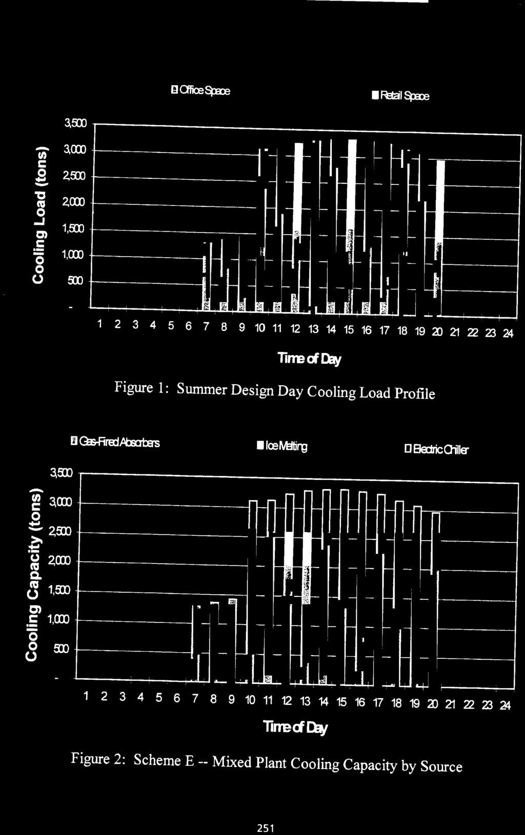
5 ~2lZZ324 lirrred4;n Figure 1 : Summer Design Day Cooling Load Profile Figure 2: Scheme E -- Mixed Plant Cooling Capacity by Source
6 REFRIGERATION SOURCE CHILLER PLANT SCHEME Gas Absorbers Electric Chillers Thermal Stomge INSTALLED CAPACITY ANNUAL CONSUMPTION (ton-hrs) A Gas-Fired Absorption Chillers Gas-Fired Boiler Plant 3,400 Steam Absorption Chillers (100%) Electric Centrifugal Chillers with Thermal Storage Gas-Fired Absorption Chillers with Thermal Storage from (60%] (1.900) 1,360 3,400 3, (ice generation) (40%) (night-time only) Gas-Fired Absorption Chillers, Electric Centrifugal Chillers, (60%; Table 1 : Summary of Chiller Plant Schemes CHILLER PLANT SCHEME Demand Consumption (kw) (kwh) 1 1 A Gas-Fired Absorption Chillers , I ELECTRICITY I NATURAL GAS Cost 1 50 (US. S) Demand (Bhrlh x 10') 1 42,707 Consumption (Btu x Cost (US. S) ANNUAL ENERGY COST (US. S) RANKING, LEAST TO MOST COSTLY 2 8 Gas-Fired Boiler Plant I 794,678 I 125,837 I ,217 I Steam Absorption Chillers I I I I I I 5 Electric Centrifugal Chillers with Thermal Storage NIA NIA NIP 1 D Gas-Fired Absorption Chillers with Thermal Storage from Electric Centrifugal Chillers % 4 E Gas-Fired Absorption Chillers, Electric Centrifugal Chillers, and Thermal Storage 1, , , ,081 3 Table 2: Annual Cooling Energy Consumption and Costs