Below ground System of pipework required to carry waste fluids from building to disposal site.
|
|
|
- Nancy Lucas
- 5 years ago
- Views:
Transcription


1 1
2 Below ground System of pipework required to carry waste fluids from building to disposal site. Disposal site County Council sewage treatment facility. Septic tank system or alternative systems 2
 should be")


3 1. Layout should be as simple as possible. 2. Changes in direction and gradient (slope) should be minimised. 3. Access points should be provided where two or more branches connect into each other 4. Man hole used for depths greater than 1meter. 5. Connections should be made obliquely and in the direction of the flow. 3


4 Rubber seals on upvc pipes. Ends should be lubricated to ensure seal isn t dislodged when joining. Joints should be squarely made. 4


5 Life span of materials used to make pipes. concrete cast iron upvc Effects of moisture, building settlement and ground movement on the drain. Effect of chemical attack on the pipes and joints from effluent and soil water. Crushing of pipes. Root penetration. 5
6 Blockages are avoided by: Ensuring adequate diameter of drain. Smooth internal surfaces. Properly aligned joints. No reduction of diameter in direction of flow. Ensuring pipes laid at correct gradient (slope) 1:40. self cleansing 6
7 7
8 8
9 There are a number of different types of access to a below-ground drainage system. 9

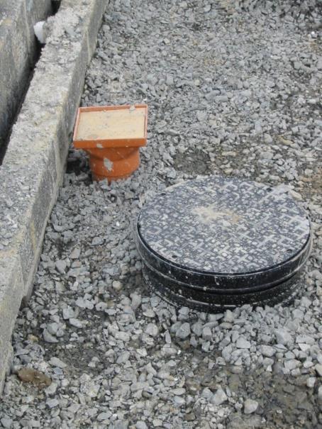
10 Gully connection between above-ground drainage system and below-ground drainage system. P trap gully 10


11 Ø40 wastewater pipe Grate or cover Gully hopper G.L P trap gully Ø100 drain Concrete base 11

12 Less than 600mm deep. Allows for clearing of blockages using rods. used when 2 or more pipes joining. change in direction. change in invert level. 12

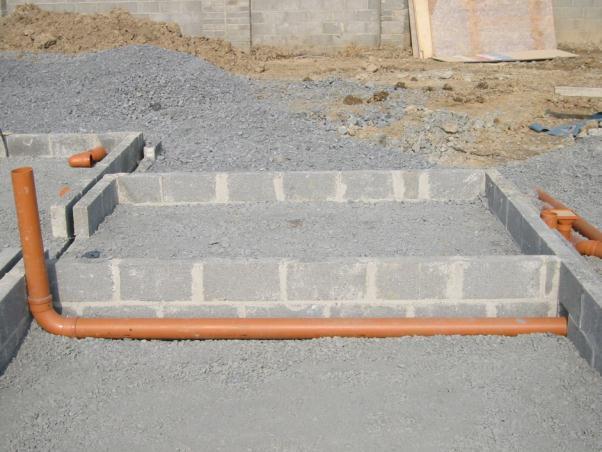
13 change in direction Access junction 13

14 Access junction 14

15 Gullys & access junctions Gullys Access junction 15
16 16
17 17


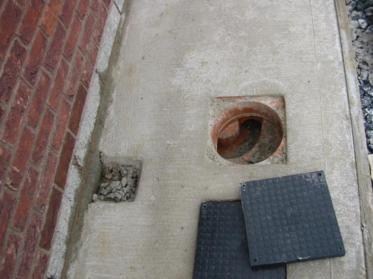
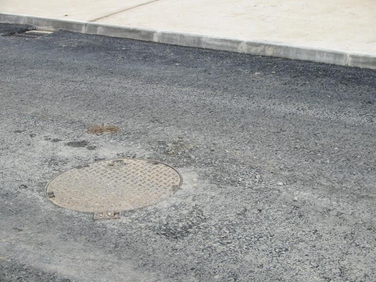
18 Provide means of access by person for maintenance. Used when the depth of the pipes is more than 1 metre Constructed using ready-made concrete rings or upvc. 18
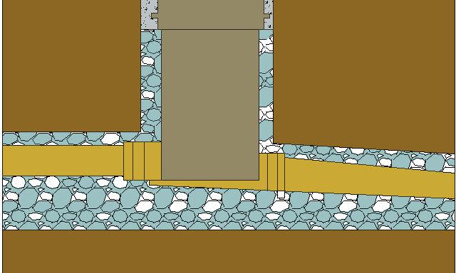

19 Inspection chamber < 1m deep 19

20 Manholes used on depths greater than one meter deep for clearing blockages by climbing down into chamber. 20


21 Built-in ladder rungs - deep concrete chambers only 21

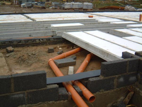
22 Branch drains 22
23 23

24 Cast iron cover. Brick levelling course. 600 min Branch drain Precast concrete cover slab. Precast concrete chamber sections. Benching (slope) Precast concrete base Main drain 24
25 Surface water collected on roofs, footpaths, and driveways must be removed. There are two ways of approaching this problem: Separate system. Combined systems. 25
26 Separate system provides separate drainage for foul and surface water. 26

27 Separate system Rain water down-pipe. Waste water. Access junction. Inspection chamber. Soil/foul sewer. Surface/rainwater drain. Inspection chamber. Surface water drain. 27
28 Separate system Kitchen Foul water Access junction. Gully Garage R.W.P House Inspection chamber. Driveway Inspection chamber Road gully Foul water main sewer. Surface water main sewer. 28

29 Combined system Rain water down-pipe. Waste water Inspection chamber Common drain Public sewer Inspection chamber 29

30 Combined system Kitchen Access junction Gully Garage R.W.P House Inspection chamber Driveway Foul water Road gully Combined main sewer 30
31 The main benefit of the separate system is that the relatively clean surface water can be disposed of into a local river rather than unnecessarily treating it at a wastewater treatment plant. The disadvantage is the cost of the extra pipe-work and excavation required. 31
32 The main purpose for testing drains is to ensure that they are airtight. This should be done after the trench is back-filled. Preliminary testing should take place before the back-filling is done. 32
33 Water test Air test Smoke test MUST KNOW ALL THREE TESTS. SEE TEXT BOOK FOR TESTS 33