Soil-Structure Interaction (SSI) Testing Facility and Capabilities at Lehigh University
|
|
|
- Roland Bishop
- 5 years ago
- Views:
Transcription

1 Soil-Structure Interaction (SSI) Testing Facility and Capabilities at Lehigh University Muhannad T. Suleiman, Ph.D. Associate Professor Civil and Environmental Engineering Department 1

2 SSI Testing Facility Reaction frame Upper soil box Lower soil box Drainage base Drainage pipe 2

3 SSI Testing Facility 3
4 SSI Testing Facility Lateral Load Tests on Scaled Deep Foundations Axial Load Tests on Scaled Ground Improvement Foundations (aggregate Piers and Pervious Concrete Foundations) 4

5 SSI Testing Facility Axial Pullout Tests (Simulating Geothermal Foundations) Cyclic Lateral Loading (Simulating Foundations Supporting Offshore Wind Turbines) 5

6 SSI Testing Facility 6

7 SSI Testing Facility 7
8 SSI Testing Facility 8
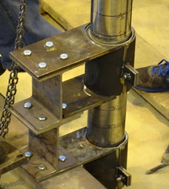
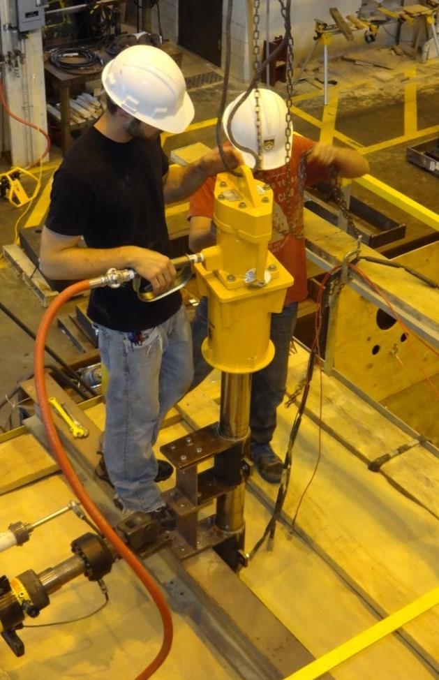
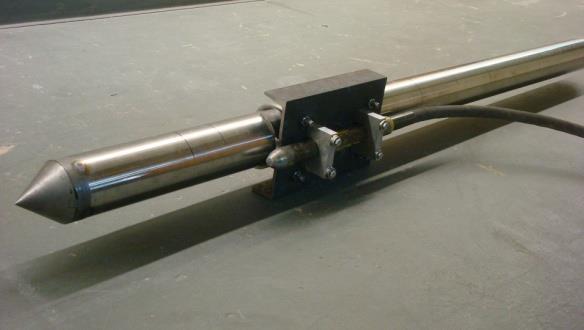
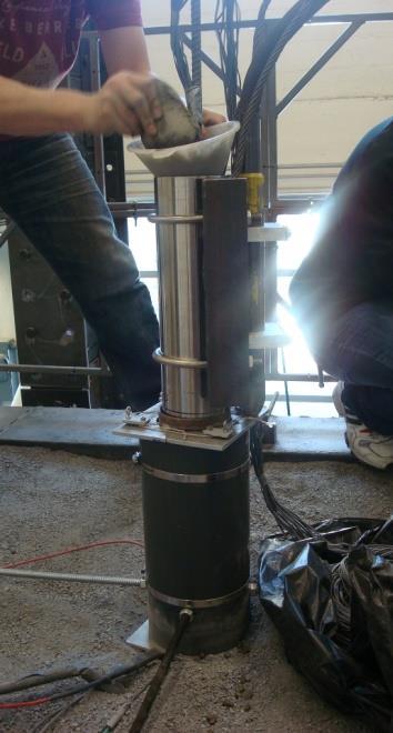
9 Simulating Foundation Installation Pile Driver Cone tip Mandrel Vibrator Guiding system Guiding system 9


10 Field Testing and Instrumentation Axial Load Test on Instrumented Controlled Modulus Columns (CMC) 10


11 Field Testing and Instrumentation Shape Acceleration Array (SAA) Soil Instrumentation Surrounding CMC Push-in Pressure Sensor 11
 System")
12 Instrumentation Shape Acceleration Arrays (SAA) Tactilus Pressure Sheets Loading Stub SAA Pile Digital Image Correlation (DIC) System 12

13 Load direction Digital Image Correlation System (DIC) Front Pile V U Transverse direction Load Moved box location Original box location 13
14 Load direction Digital Image Correlation System (DIC) soil box displacement: mm pile displacement: 78.7 mm soil box displacement: mm Front V U global Y location (mm) V (mm) Moved location Original location global Y location (mm) W (mm) Transverse direction global X location (mm) global X location (mm) Load direction 14
 Front Pile")
 (b)")
15 Load direction Digital Image Correlation System (DIC) Front Pile V U Transverse direction Moved location Original location (a) (b) (c) (d) 15
 400 600 800 1000 1200 1400 Pile Rotation point shifts upward Load (N) 446 890 1338 1780 2230 2676 3122 3568 3799 1600")
16 Shape Acceleration Arrays (SAAs) Lateral displacement (mm) Soil Surface 200 Depth along the pile (mm) Pile Rotation point shifts upward Load (N)


17 Soil-Pile Interaction Pressure Pressure sheets H I F G H Load H Load H G F I G Pile I Load Soil surface F Depths below soil surface: 156 mm H I F G (b) H Pressure sheets 574 mm I F G H 1019 mm (c) 1357 mm Front of the pile Back of the pile (a) (d) 17


18 Soil-Pile Interaction Pressure Pressure sheets Load H G F H I F G H H I F G H Pile I Load Soil surface Depths below soil surface: 156 mm Max. soil pressure at 465 mm below soil surface Pressure sheets (b) 1780N (c) 2676N 574 mm H I F G H H I F G H 1019 mm Max. soil pressure 1357 mm Back of the pile (a) Front of the pile (d) 3568N (e) 3799N 18


 2676N I F G H 574 mm Rotation")
 Front of")
 3799N 19")
19 Pressure sheets Load Soil-Pile Interaction Pressure H G F I F G H I F G H I F G H Pile Load Depths below soil surface: 156 mm I Soil surface Rotation point of pile at 1273 mm below soil surface Pressure sheets (b) 890N I F G H (c) 1780N I F G H (d) 2676N I F G H 574 mm Rotation point of pile 1062 mm below soil surface 1019 mm Rotation point of pile at 1273 mm below soil surface 1357 mm Back of the pile (a) Front of the pile (e) 3568N (f) Transition from 3568N to 3799N (g) 3799N 19
20 Soil-Pile Interaction Pressure Soil Surface Pile at deformed location Load Pile at original location Shear stresses between pile and soil Normal stresses due to pile movement into the soil Depth along the pile (mm) Load (N) Pile Soil reaction (N/mm) 20
21 Geothermal Piles & Temperature Sensors Actuator Fluid hoses Pile Insulation Data acquisition 21
22 Geothermal Piles & Temperature Sensors Reaction frame Reference Beams Cables connected to a hydraulic hand pump Hydraulic actuator Displacement transducers Fluid circulating bath Rebar Load cell Aluminum u-tubes connected to circulating bath Dry bar sand Foam board insulation Null Pressure Sensor Thermocouple
 ID 4.72 mm 152 67.7 Soil Surface 2 aluminum 2 Aluminum 285 heat heat exchange exchange loops loops OD 6.35 mm OD 6.35 mm ID 4.72 mm ID 4.")

23 threaded bar (9.5 mm diameter) 152 Geothermal Piles & Temperature Sensors 2 Aluminum Steel heat Steel reinforcing reinforcing exchange loops threaded threaded 285 bar bar OD 6.35 mm (9.5 mm (9.5 mm diameter) ID 4.72 mm Soil Surface 2 aluminum 2 Aluminum 285 heat heat exchange exchange loops loops OD 6.35 mm OD 6.35 mm ID 4.72 mm ID 4.72 mm Aluminum heat exchange loops 17 mm (clear cover) Thermocouples on the pile surface Steel threaded rebar Radial strain gauge Radial strain gauge Axial strain gauge Axial strain gauge Thermocouple Thermocouple Pile cross-section Diaphragm pressure sensor Pile: After Concrete Casting Figure 1. Schematic of the test unit showing pile instrumentation and cross section. Note: plot not to scale, dimensions are in mm. 23
24 Geothermal Piles & Temperature Sensors Heat Pump Operation 1hr running time Beginning of thermal cycles 1 st cycle Operation of heat pump N-1 th cycle 1 hr Change in temperature of the pile Beginning of pull-out loading Change in Temperature 15 min stoppage time Elaspsed Time 24
25 Geothermal Piles & Temperature Sensors 20 Change in Temperature ( o C) Just before thermal cycles EOH (cycle 1) EOH (cycle 5) EOH (cycle 10) EOH (cycle 30) EOH (cycle 60) EOH (cycle 80) Just before pull-out loading Distance from Pile Surface (mm) 25
26 Distance along the pile (mm) Temperature Sensors and Distribution Water in Surface of the Sand Distance from the surface of the pile (mm) 26
27 Distance along the pile (mm) Temperature Sensors and Distribution Water in Surface of the Sand Distance from the surface of the pile (mm) 27
28 Distance along the pile (mm) Temperature Sensors and Distribution Water in Surface of the Sand Distance from the surface of the pile (mm) 28
29 Distance along the pile (mm) Temperature Sensors and Distribution Water in Surface of the Sand Distance from the surface of the pile (mm) 29

30 Distance along the pile (mm) Temperature Sensors and Distribution Water in Surface of the Sand Distance from the surface of the pile (mm) 30
31 Distance along the pile (mm) Geothermal Piles & Temperature Sensors Water in Surface of the Sand Distance from the surface of the pile (mm) 31
32 Distance along the pile (mm) Geothermal Piles & Temperature Sensors Water in Surface of the Sand Distance from the surface of the pile (mm) 32
33 Distance along the pile (mm) Geothermal Piles & Temperature Sensors Water in Surface of the Sand Distance from the surface of the pile (mm) 33
34 Distance along the pile (mm) Geothermal Piles & Temperature Sensors Water in Surface of the Sand Distance from the surface of the pile (mm) 34

35 Distance along the pile (mm) Geothermal Piles & Temperature Sensors Water in Surface of the Sand Distance from the surface of the pile (mm) 35
36 Distance along the pile (mm) Geothermal Piles & Temperature Sensors Water in Surface of the Sand Distance from the surface of the pile (mm) 36
37 Distance along the pile (mm) Geothermal Piles & Temperature Sensors Water in Surface of the Sand Distance from the surface of the pile (mm) 37

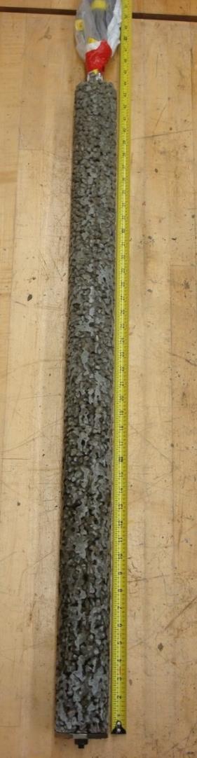
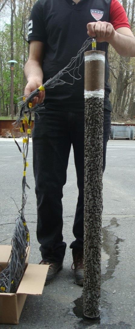
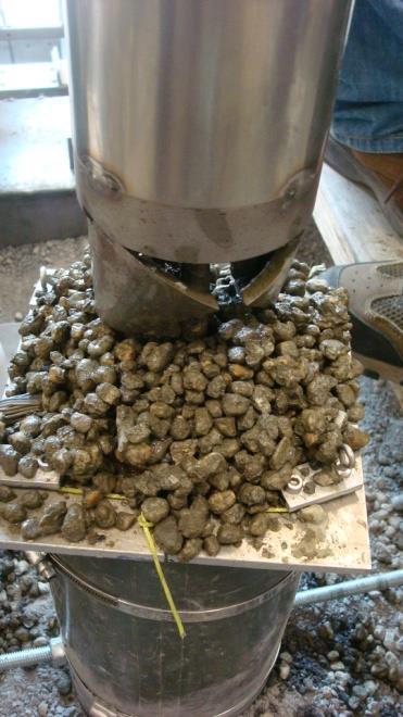
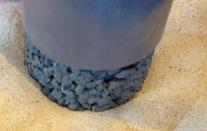
38 Pervious Concrete Ground Improvement Pile 38


39 Test Units and Axial Loading Actuator Bacteria and media Displacement transducers Pile Pile Pervious Concrete Pile During MICP treatment During loading 39
")
 ~ 4 times Untreated 872 lb 60 2.")
 10 20 30 40 50 Uplift displacement (mm) 229 mm 140 mm Below")
40 Test Units and Axial Loading Five vertical load tests: Two subjected to axial tension and three subjected to axial compression Uplift displacement (inch) Uplift load (lbs) lb (919 N) ~ 4 times Untreated 872 lb MICP-treated (3879 N) Uplift load (N) Uplift displacement (mm) 229 mm 140 mm Below the pile tip 76 mm Pile diameter: 76 mm Soil surface 40
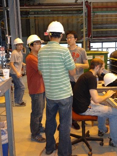
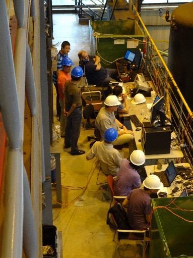
41 Participation of Students 41